CN210832881U - Drying device for cement dry-method production - Google Patents
Drying device for cement dry-method production Download PDFInfo
- Publication number
- CN210832881U CN210832881U CN201921017816.XU CN201921017816U CN210832881U CN 210832881 U CN210832881 U CN 210832881U CN 201921017816 U CN201921017816 U CN 201921017816U CN 210832881 U CN210832881 U CN 210832881U
- Authority
- CN
- China
- Prior art keywords
- shell
- drying device
- fixedly connected
- casing
- side wall
- Prior art date
- Legal status (The legal status is an assumption and is not a legal conclusion. Google has not performed a legal analysis and makes no representation as to the accuracy of the status listed.)
- Active
Links
Images

Abstract
The utility model discloses a drying device is used in cement dry process production, which comprises a housin, the casing sets up for cavity, the upper end of casing is equipped with the feed inlet rather than inside intercommunication, one side lateral wall of casing still is equipped with the discharge gate with the inside intercommunication of casing, fixedly connected with arc heat-conducting plate in the casing, and the lower extreme fixedly connected with arc electric plate of arc heat-conducting plate, one side lateral wall fixedly connected with motor of discharge gate is kept away from to the casing, and the motor has the pivot through the coupling joint, the pivot runs through the lateral wall of casing and extends to in the casing, the lateral wall of pivot is through a plurality of connecting rod fixedly connected with shovel that rolls. This device easy operation, convenient to use drives the pivot through the motor and rotates to make the connecting rod drive the shovel that rolls and shovel the material, make the material raise, make the material can fully contact with the arc heat-conducting plate, with higher speed the material is dried, improved work efficiency.
Description
Technical Field
The utility model relates to a cement dry processing technology field specifically is a drying device is used in cement dry process production.
Background
The processing of cement is divided into a wet method and a dry method, wherein the wet method is to prepare slurry by grinding raw materials and directly add the slurry into a rotary kiln for calcination, so that heat consumption is needed to evaporate water, and the heat consumption is high; the dry method is to prepare the raw material into dry powder, add the dry powder into a preheater or add the dry powder into a rotary kiln for calcination, and the heat consumption is lower than that of the wet method, and the dry method has various types according to different kiln types and has different heat consumption.
In the existing cement dry production process, the cement raw materials need to be dried, generally, the cement raw materials are heated to evaporate water in the cement raw materials and then dried, but in the cement raw materials drying process, because the materials are not uniformly heated, water vapor is difficult to discharge, so that a large amount of time is consumed for drying the cement raw materials, and the working efficiency is reduced; therefore, a drying device for dry production of cement is provided.
SUMMERY OF THE UTILITY MODEL
An object of the utility model is to provide a drying device is used in cement dry process production to solve the problem that proposes in the above-mentioned background art.
In order to achieve the above object, the utility model provides a following technical scheme: the utility model provides a drying device is used in cement dry process production, includes the casing, the casing sets up for cavity, the upper end of casing is equipped with the feed inlet rather than inside intercommunication, one side lateral wall of casing still is equipped with the discharge gate with the inside intercommunication of casing, fixedly connected with arc heat-conducting plate in the casing, and the lower extreme fixedly connected with arc electric plate of arc heat-conducting plate, one side lateral wall fixedly connected with motor of discharge gate is kept away from to the casing, and the motor has the pivot through the coupling joint, the pivot runs through the lateral wall of casing and extends to in the casing, the lateral wall of pivot rolls the shovel through a plurality of connecting rod fixedly connected with, the upside lateral wall of casing is equipped with the bleeder vent rather than inside intercommunication, the lower extreme of casing is equipped with the supporting.
Preferably, the supporting mechanism includes the base, the base is located the lower extreme setting of casing, first bracing piece and the second bracing piece that the upper end fixedly connected with symmetry of base set up, the upper end of first bracing piece rotates with the downside lateral wall of casing to be connected, and the upper end of second bracing piece offsets with the downside lateral wall of casing and sets up, the upside lateral wall of base still rotates and is connected with the cylinder, and the output of cylinder is connected with the piston rod, the upper end of piston rod rotates with the downside lateral wall of casing to be connected, and the cylinder is close to the setting of second bracing piece.
Preferably, the opening of the feed inlet is also rotatably connected with a cover plate.
Preferably, the lower end of the base is fixedly connected with two groups of locking universal wheels which are symmetrically arranged.
Preferably, the surface of the shell is sprayed with an anti-corrosion paint.
Preferably, the inner wall of the upper side of the shell is also fixedly connected with a blocking net.
Compared with the prior art, the beneficial effects of the utility model are that:
1. the utility model is simple in operation, convenient to use drives the pivot through the motor and rotates to make the connecting rod drive the shovel that rolls and shovel the material, make the material raise, make the material can fully contact with the arc heat-conducting plate, the material is dried with higher speed, has improved work efficiency.
2. The utility model discloses a set up supporting mechanism, be convenient for collect the material in the casing, set up the apron through the opening part at the feed inlet, when drying the material, need cover the feed inlet on the apron, prevent when the material is kicked up, the material flies out from the opening part of feed inlet, through setting up the locking universal wheel, the mobile device of being convenient for brakes with to the device, through the surface spraying anticorrosion lacquer at the casing, the corrosion resistance of casing has been improved, thereby the life of device has been improved, keep off the net through setting up, block the material of kicking up, prevent that the material from flying out from venthole department.
Drawings
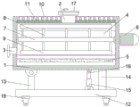
FIG. 1 is a schematic sectional view of the front view of the present invention;
fig. 2 is a schematic side sectional structural view of the middle housing of the present invention.
In the figure: 1. a housing; 2. a feed inlet; 3. a discharge port; 4. an arc-shaped heat conducting plate; 5. an arc-shaped electric heating plate; 6. a motor; 7. a rotating shaft; 8. a connecting rod; 9. turning and shoveling; 10. air holes are formed; 11. blocking the net; 12. a base; 13. a first support bar; 14. a second support bar; 15. a cylinder; 16. a piston rod; 17. a cover plate; 18. and locking the universal wheels.
Detailed Description
The technical solutions in the embodiments of the present invention will be described clearly and completely with reference to the accompanying drawings in the embodiments of the present invention, and it is obvious that the described embodiments are only some embodiments of the present invention, not all embodiments. Based on the embodiments in the present invention, all other embodiments obtained by a person skilled in the art without creative work belong to the protection scope of the present invention.
Referring to fig. 1-2, the present invention provides a technical solution: the utility model provides a drying device is used in cement dry process production, includes casing 1, its characterized in that: the shell 1 is hollow, the upper end of the shell 1 is provided with a feed inlet 2 communicated with the interior of the shell, one side wall of the shell 1 is also provided with a discharge outlet 3 communicated with the interior of the shell 1, an arc heat-conducting plate 4 is fixedly connected in the shell 1, an arc electric heating plate 5 is fixedly connected at the lower end of the arc heat-conducting plate 4, one side wall of the shell 1 far away from the discharge outlet 3 is fixedly connected with a motor 6, the motor 6 is connected with a rotating shaft 7 through a coupler, the rotating shaft 7 penetrates through the side wall of the shell 1 and extends into the shell 1, the side wall of the rotating shaft 7 is fixedly connected with a rolling shovel 9 through a plurality of connecting rods 8, the upper side wall of the shell 1 is provided with an air vent 10 communicated with the interior of the shell, when the device is used, materials are conveyed into the shell 1 from the feed inlet 2, and heat, therefore, the arc-shaped heat conduction plate 4 transfers heat to the materials, moisture on the materials is heated and evaporated, the moisture is evaporated and is discharged out of the shell 1 from the air holes 10, the materials are dried, in the process of drying the materials, the motor 6 drives the rotating shaft 7 to rotate, the connecting rod 8 drives the rolling shovel 9 to shovel the materials, the materials are lifted, the materials can be fully contacted with the arc-shaped heat conduction plate 4, the drying of the materials is accelerated, and the working efficiency is improved;
the lower end of the shell 1 is provided with a supporting mechanism matched with the shell, the supporting mechanism comprises a base 12, the base 12 is arranged at the lower end of the shell 1, the upper end of the base 12 is fixedly connected with a first supporting rod 13 and a second supporting rod 14 which are symmetrically arranged, the upper end of the first supporting rod 13 is rotatably connected with the lower side wall of the shell 1, the upper end of the second supporting rod 14 is abutted against the lower side wall of the shell 1, the upper side wall of the base 12 is further rotatably connected with an air cylinder 15, the output end of the air cylinder 15 is connected with a piston rod 16, the upper end of the piston rod 16 is rotatably connected with the lower side wall of the shell 1, the air cylinder 15 is arranged close to the second supporting rod 14, when the dried materials in the shell 1 need to be collected, the discharge port 3 is opened, the air cylinder 15 is started, the air cylinder 15 controls the piston rod 16 to extend, so as to jack up one end, the collection of materials is convenient;
the opening of the feed port 2 is also rotatably connected with a cover plate 17, the cover plate 17 is arranged at the opening of the feed port 2, when materials are dried, the feed port 2 needs to be covered by the cover plate 17, and the materials are prevented from flying out of the opening of the feed port 2 when the materials are lifted;
two groups of symmetrically arranged locking universal wheels 18 are fixedly connected to the lower end of the base 12, and the locking universal wheels 18 are arranged, so that the device can be moved and braked conveniently;
the surface of the shell 1 is sprayed with the anti-corrosion paint, and the anti-corrosion paint is sprayed on the surface of the shell 1, so that the corrosion resistance of the shell 1 is improved, and the service life of the device is prolonged;
the upper side inner wall of casing 1 is fixedly connected with and is kept off net 11, keeps off net 11 through setting up, blocks the material of raiseing, prevents that the material from following bleeder vent 10 departure.
It is noted that, herein, relational terms such as first and second, and the like may be used solely to distinguish one entity or action from another entity or action without necessarily requiring or implying any actual such relationship or order between such entities or actions. Also, the terms "comprises," "comprising," or any other variation thereof, are intended to cover a non-exclusive inclusion, such that a process, method, article, or apparatus that comprises a list of elements does not include only those elements but may include other elements not expressly listed or inherent to such process, method, article, or apparatus.
Although embodiments of the present invention have been shown and described, it will be appreciated by those skilled in the art that changes, modifications, substitutions and alterations can be made in these embodiments without departing from the principles and spirit of the invention, the scope of which is defined in the appended claims and their equivalents.
Claims (6)
1. The utility model provides a drying device is used in cement dry process production, includes casing (1), its characterized in that: the improved energy-saving gas-liquid separator is characterized in that the shell (1) is arranged in a hollow manner, the upper end of the shell (1) is provided with a feed inlet (2) communicated with the interior of the shell, one side wall of the shell (1) is further provided with a discharge outlet (3) communicated with the interior of the shell (1), the shell (1) is fixedly connected with an arc heat-conducting plate (4), the lower end of the arc heat-conducting plate (4) is fixedly connected with an arc electric heating plate (5), one side wall of the shell (1) far away from the discharge outlet (3) is fixedly connected with a motor (6), the motor (6) is connected with a rotating shaft (7) through a coupler, the rotating shaft (7) penetrates through the side wall of the shell (1) and extends into the shell (1), the side wall of the rotating shaft (7) is fixedly connected with a rolling shovel (9) through a plurality of connecting rods, the lower end of the shell (1) is provided with a supporting mechanism matched with the shell.
2. The drying device for cement dry production according to claim 1, wherein the drying device comprises: the supporting mechanism comprises a base (12), the base (12) is located at the lower end of the shell (1) and is arranged, a first supporting rod (13) and a second supporting rod (14) are symmetrically arranged at the upper end of the base (12), the upper end of the first supporting rod (13) is rotatably connected with the lower side wall of the shell (1), the upper end of the second supporting rod (14) is abutted to the lower side wall of the shell (1), the upper side wall of the base (12) is rotatably connected with a cylinder (15), the output end of the cylinder (15) is connected with a piston rod (16), the upper end of the piston rod (16) is rotatably connected with the lower side wall of the shell (1), and the cylinder (15) is arranged close to the second supporting rod (14).
3. The drying device for cement dry production according to claim 1, wherein the drying device comprises: the opening part of the feed inlet (2) is also rotatably connected with a cover plate (17).
4. The drying device for cement dry production according to claim 2, wherein the drying device comprises: the lower end of the base (12) is fixedly connected with two groups of locking universal wheels (18) which are symmetrically arranged.
5. The drying device for cement dry production according to claim 1, wherein the drying device comprises: the surface of the shell (1) is sprayed with anti-corrosion paint.
6. The drying device for cement dry production according to claim 1, wherein the drying device comprises: the inner wall of the upper side of the shell (1) is also fixedly connected with a blocking net (11).
Priority Applications (1)
| Application Number | Priority Date | Filing Date | Title |
|---|---|---|---|
| CN201921017816.XU CN210832881U (en) | 2019-07-02 | 2019-07-02 | Drying device for cement dry-method production |
Applications Claiming Priority (1)
| Application Number | Priority Date | Filing Date | Title |
|---|---|---|---|
| CN201921017816.XU CN210832881U (en) | 2019-07-02 | 2019-07-02 | Drying device for cement dry-method production |
Publications (1)
| Publication Number | Publication Date |
|---|---|
| CN210832881U true CN210832881U (en) | 2020-06-23 |
Family
ID=71259199
Family Applications (1)
| Application Number | Title | Priority Date | Filing Date |
|---|---|---|---|
| CN201921017816.XU Active CN210832881U (en) | 2019-07-02 | 2019-07-02 | Drying device for cement dry-method production |
Country Status (1)
| Country | Link |
|---|---|
| CN (1) | CN210832881U (en) |
Cited By (1)
| Publication number | Priority date | Publication date | Assignee | Title |
|---|---|---|---|---|
| CN114085691A (en) * | 2021-12-08 | 2022-02-25 | 联合优发生物质能源徐州有限公司 | Discharge mechanism is used in production of biomass energy granule |
-
2019
- 2019-07-02 CN CN201921017816.XU patent/CN210832881U/en active Active
Cited By (1)
| Publication number | Priority date | Publication date | Assignee | Title |
|---|---|---|---|---|
| CN114085691A (en) * | 2021-12-08 | 2022-02-25 | 联合优发生物质能源徐州有限公司 | Discharge mechanism is used in production of biomass energy granule |
Similar Documents
| Publication | Publication Date | Title |
|---|---|---|
| CN2809544Y (en) | Breaking type rotary cylinder drying machine | |
| CN102235807A (en) | Rotary drum vacuum dryer | |
| CN210832881U (en) | Drying device for cement dry-method production | |
| CN111854330A (en) | Solid waste recycling and drying device and drying method thereof | |
| CN208635507U (en) | A kind of ceramic tile Quick-air-drying device | |
| CN212604015U (en) | A finished product label quick drying device for label printing machine | |
| CN210425885U (en) | Drying device required by garbage treatment process | |
| CN212109333U (en) | Raw material drying machine for floor base material processing | |
| CN210718556U (en) | Drying device is used in preparation of fire-retardant wood-plastic composite | |
| CN109405519A (en) | A kind of combined type cream mud dryer | |
| CN215724734U (en) | Powder drying equipment | |
| CN218012990U (en) | Rubbing crusher is used in production of dry formula living beings granule | |
| CN203403001U (en) | Disc type pasty material film continuous dryer | |
| CN203550445U (en) | Drum-type drying device | |
| CN212566763U (en) | Energy-saving waste plastic particle drying device | |
| CN203183971U (en) | Energy-saving one-step pelletizer | |
| CN211695695U (en) | Chemical material stirring drying device | |
| CN210399795U (en) | Special quick dryer for pepper fruits after peeling and degumming | |
| CN203798102U (en) | Roller drying system special for garbage slurry | |
| CN213066886U (en) | A stoving edulcoration device for fodder | |
| CN218238151U (en) | Multichannel rotary drum dryer | |
| CN220632595U (en) | High-efficient intelligent coating machine | |
| CN203964565U (en) | Novel drum type drying equipment feed end mounting structure | |
| CN210346171U (en) | Efficient drying-machine is used in soil conditioner production | |
| CN219890037U (en) | Solid matter flash dryer |
Legal Events
| Date | Code | Title | Description |
|---|---|---|---|
| GR01 | Patent grant | ||
| GR01 | Patent grant |