CN210826628U - High-efficient simple and easy foreskin muscle structure - Google Patents
High-efficient simple and easy foreskin muscle structure Download PDFInfo
- Publication number
- CN210826628U CN210826628U CN201921155250.7U CN201921155250U CN210826628U CN 210826628 U CN210826628 U CN 210826628U CN 201921155250 U CN201921155250 U CN 201921155250U CN 210826628 U CN210826628 U CN 210826628U
- Authority
- CN
- China
- Prior art keywords
- plate
- sliding
- fixedly mounted
- foreskin
- cover
- Prior art date
- Legal status (The legal status is an assumption and is not a legal conclusion. Google has not performed a legal analysis and makes no representation as to the accuracy of the status listed.)
- Active
Links
Images


Abstract
The utility model discloses a high-efficiency simple foreskin tendon structure, which mainly comprises a sliding plate, a sliding frame, a swinging plate, a fixed plate, an inserting sheet and a presser foot, wherein an adjusting port is formed in the left side of the sliding plate; fixed plate right-hand member fixed mounting has down to change the cover, and lower cover mid-mounting rotates to install and changes the round pin, changes the round pin outside and is located down to change the cover top and rotate and install and change the cover, and it has the swing board to rotate cover front end fixed mounting, and swing board top middle part connects soon installs adjusting bolt, and adjusting bolt middle part cover is established and is installed the balladeur train. The utility model discloses structurally reasonable in design, this equipment package underpants rubber band round, the position of automatic spacing underpants rubber band reduces the action that the adjustment was pacified, reduces the technology degree of difficulty, and the quality reaches guest's requirement, raises the efficiency greatly.
Description
Technical Field
The utility model relates to a clothing field specifically is a high-efficient simple and easy foreskin muscle structure.
Background
With the continuous development of domestic clothing industry in recent years, the sewing equipment industry is also continuously upgraded, various sewing equipment is also continuously emerged, various auxiliary parts are indispensable in the sewing equipment, and 1, auxiliary parts such as presser feet are required; 2. auxiliary parts such as side seam devices; 3. feeding mode type auxiliary parts; in addition to these three most basic and most important aids, there are inlay-type aids, tucker-type aids, threaders, zigzag stitchers, buttonholes, tape stretchers, presser foot lifts, power retractors, and the like. Although various auxiliary parts are small, due to the use of the auxiliary parts, the sewing equipment is added with new functions, and the operation is more labor-saving, high-speed and efficient, so that greater economic benefit is obtained.
The conventional flat car for wrapping a trouser top by a circle of rubber band is time-consuming; the position of the rubber band at the underpants is adjusted by hand, and the rubber band is limited, so that complicated adjustment and smoothing actions are realized, the process difficulty is increased, and the quality is difficult to meet the requirements; and each piece of processing time of the existing process is about one and a half, and the efficiency is low.
Disclosure of Invention
An object of the utility model is to provide a high-efficient simple and easy rubber band wrapping structure to solve the problem that proposes in the above-mentioned background art.
In order to achieve the above object, the utility model provides a following technical scheme:
a high-efficiency simple foreskin tendon structure mainly comprises a sliding plate, a sliding frame, a swinging plate, a fixing plate, an inserting piece and a presser foot, wherein an adjusting opening is formed in the left side of the sliding plate;
the fixed plate right-hand member fixed mounting has down to change the cover, and lower cover middle part rotates and installs and changes the round pin, changes the round pin outside and is located to change cover top and rotate and install and change the cover, and it has the swing plate to rotate cover front end fixed mounting, and swing plate top middle part connects soon installs adjusting bolt, and adjusting bolt middle part cover is established and is installed the balladeur train, and balladeur train middle part inboard is seted up with adjusting bolt complex slide opening, adjusting bolt runs through the balladeur train via the slide opening, and balladeur train left end fixed mounting has the inserted sheet, the presser foot is located the inserted sheet rear, presser.
As a further aspect of the present invention: and the rear part of the left side of the inserting piece is fixedly provided with a spreading head.
As a further aspect of the present invention: the presser foot mainly includes branch, staple bolt, limiting plate and exhibition flat board, branch bottom fixed mounting has the assembly jig, and the assembly jig left end fixed mounting has the extension board, and extension board bottom fixed mounting has the limiting plate, the anterior fixed mounting in assembly jig bottom has the exhibition flat board, branch top fixed mounting has the staple bolt, and staple bolt upper portion inboard connects soon to install tightens up the bolt.
As a further aspect of the present invention: the inner side of the middle part of the unfolding plate is provided with a needle opening.
As a further aspect of the present invention: the front ends of the limiting plate and the unfolding plate are both in an arc shape with a high front end and a low back end.
Compared with the prior art, the beneficial effects of the utility model are that:
the utility model discloses structurally reasonable in design, this equipment package underpants rubber band round, the position of automatic spacing underpants rubber band reduces the action that the adjustment was pacified, reduces the technology degree of difficulty, and the quality reaches guest's requirement, raises the efficiency greatly.
Drawings
Fig. 1 is a schematic structural diagram of a high-efficiency simple rubber band wrapping structure.
Fig. 2 is a top view of the high-efficiency simple wrapping rib structure.
Fig. 3 is a schematic structural view of a presser foot overlooking angle in a high-efficiency simple wrapping rib structure.
Fig. 4 is a schematic structural diagram of a left view angle of the limiting plate in the high-efficiency simple rubber band wrapping structure.
FIG. 5 is a schematic cross-sectional view of a left side view of a flattened plate in a high-efficiency simple rubber band wrapping structure.
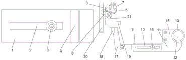
In the figure: the device comprises a sliding plate 1, an adjusting opening 2, a compression bolt 3, a blocking frame 4, a support plate 5, an assembly frame 6, an anchor ear 7, a support rod 8, a sliding frame 9, a sliding hole 10, a swinging plate 11, a rotating pin 12, an upper rotating sleeve 13, a lower rotating sleeve 14, a fixing plate 15, an adjusting bolt 16, an inserting piece 17, a spreading head 18, a spreading plate 19, a limiting plate 20 and a needle opening 21.
Detailed Description
The technical solutions in the embodiments of the present invention will be described clearly and completely with reference to the accompanying drawings in the embodiments of the present invention, and it is obvious that the described embodiments are only some embodiments of the present invention, not all embodiments. Based on the embodiments in the present invention, all other embodiments obtained by a person skilled in the art without creative work belong to the protection scope of the present invention.
In the description of the present invention, it is to be understood that the terms "center", "upper", "lower", "front", "rear", "left", "right", "vertical", "horizontal", "top", "bottom", "inner", "outer", and the like indicate orientations or positional relationships based on the orientations or positional relationships shown in the drawings, and are merely for convenience of description and for simplicity of description, and do not indicate or imply that the device or element referred to must have a particular orientation, be constructed and operated in a particular orientation, and therefore, should not be construed as limiting the present invention.
In the description of the present invention, it should be noted that unless otherwise explicitly stated or limited, the terms "mounted," "connected" and "disposed" are to be construed broadly, and may for example be fixedly connected, disposed, detachably connected, disposed, or integrally connected and disposed. The specific meaning of the above terms in the present invention can be understood in specific cases to those skilled in the art.
Referring to fig. 1 to 5, in the embodiment of the present invention, an efficient and simple foreskin reinforcement structure mainly includes a sliding plate 1, a sliding frame 9, a swing plate 11, a fixing plate 15, an insertion sheet 17 and a presser foot, an adjusting opening 2 is formed inside the left side of the sliding plate 1, a pressing bolt 3 is installed at the position of the sliding plate 1, which is located at the adjusting opening 2, in a penetrating manner, and a blocking frame 4 is fixedly installed at the right top of the sliding plate 1; the sewing machine is characterized in that a lower rotating sleeve 14 is fixedly mounted at the right end of the fixing plate 15, a rotating pin 12 is rotatably mounted in the middle of the lower rotating sleeve 14, an upper rotating sleeve 13 is rotatably mounted above the lower rotating sleeve 14 on the outer side of the rotating pin 12, a swinging plate 11 is fixedly mounted at the front end of the upper rotating sleeve 13, an adjusting bolt 16 is rotatably mounted in the middle of the top end of the swinging plate 11, a sliding frame 9 is mounted in the middle of the adjusting bolt 16 in a sleeved mode, a sliding hole 10 matched with the adjusting bolt 16 is formed in the inner side of the middle of the sliding frame 9, the adjusting bolt 16 penetrates through the sliding frame 9 through the sliding hole 10, an inserting piece 17 is fixedly mounted at the left end of.
And a spreading head 18 is fixedly arranged at the rear part of the left side of the inserting sheet 17.
The presser foot mainly includes branch 8, staple bolt 7, limiting plate 20 and exhibition flat board 19, 8 bottom fixed mounting of branch has assembly jig 6, and 6 left end fixed mounting of assembly jig has extension board 5, and 5 bottom fixed mounting of extension board have limiting plate 20, 6 front portion fixed mounting in bottom of assembly jig have exhibition flat board 19, 8 top fixed mounting of branch has staple bolt 7, and staple bolt 7 upper portion inboard connects soon installs tightening bolt.
The needle opening 21 is arranged on the inner side of the middle part of the flattening plate 19.
The front ends of the limiting plate 20 and the flattening plate 19 are both in an arc shape with a high front end and a low back end.
The utility model discloses a theory of operation is:
the utility model relates to a high-efficiency simple wrapping structure, when in use, a sliding plate 1 is fixed at the feeding position of a sewing machine through a compression bolt 3, the limit range can be adjusted through an adjusting port 2 on the sliding plate 1, a fixed plate 15 is arranged at the right part of the processing position of the sewing machine through a bolt, a rubber band is clamped at the position of the upper part of a lathe bed, then a presser foot is fixed on a presser foot frame of the sewing machine through a hoop 7, a sewing machine needle head corresponds to the position of a needle opening 21, the rubber band is sleeved at the outer side of a transmission auxiliary roller according to the direction of the outer wrapping opening towards the right, the transmission auxiliary hoop is the existing equipment, the main function is to adopt two rotary rollers to tighten the rubber band, the upper layer of a ring-shaped rubber band is sleeved at the processing position of the sewing machine, the rubber band can roll for a circle along with the processing of the sewing machine, after the sleeving is completed, the wrapping cloth and the rubber band which are not on line are, the device is used for pushing the swing rod 11 to insert the insertion piece 17 into an opening of wrapping cloth, separating an upper layer and a lower layer of the wrapping cloth, fully plugging and flattening a curled part of the edge of the wrapping cloth through the unfolding head 18, blocking the right end of a rubber band in the wrapping cloth through the limiting plate 20, avoiding the right movement of the rubber band, ensuring that the rubber band and the wrapping cloth cannot be sewn together when the wrapping cloth is on line, replacing manual limiting, pressing the two ends of the wrapping cloth unfolded by the unfolding plate 19 together without manual pressing, automatically pushing the material by a sewing machine during processing, enabling the wrapping cloth and the rubber band to be on line through a needle head of the sewing machine through a needle opening 21, wrapping the rubber band in the wrapping cloth, and not sewing the rubber band and the wrapping cloth together, automatically limiting the position of the rubber band of the underpants, reducing the action of leveling adjustment, reducing the process difficulty, and greatly improving the efficiency, wherein the quality meets the requirements of customers; and each piece of the improved process is used for 0.5 minute, and the efficiency is improved by 3 times.
It is obvious to a person skilled in the art that the invention is not restricted to details of the above-described exemplary embodiments, but that it can be implemented in other specific forms without departing from the spirit or essential characteristics of the invention. The present embodiments are therefore to be considered in all respects as illustrative and not restrictive, the scope of the invention being indicated by the appended claims rather than by the foregoing description, and all changes which come within the meaning and range of equivalency of the claims are therefore intended to be embraced therein. Any reference sign in a claim should not be construed as limiting the claim concerned.
Furthermore, it should be understood that although the present description refers to embodiments, not every embodiment may contain only a single embodiment, and such description is for clarity only, and those skilled in the art should integrate the description, and the embodiments may be combined as appropriate to form other embodiments understood by those skilled in the art.
Claims (5)
1. A high-efficiency simple foreskin tendon structure mainly comprises a sliding plate (1), a sliding frame (9), a swinging plate (11), a fixing plate (15), an inserting piece (17) and a presser foot, and is characterized in that an adjusting opening (2) is formed in the left side of the sliding plate (1), a pressing bolt (3) penetrates through the position, located at the adjusting opening (2), of the sliding plate (1), and a blocking frame (4) is fixedly mounted at the right top of the sliding plate (1); the novel sewing machine is characterized in that a lower rotating sleeve (14) is fixedly mounted at the right end of a fixing plate (15), a rotating pin (12) is rotatably mounted in the middle of the lower rotating sleeve (14), the outer side of the rotating pin (12) is located above the lower rotating sleeve (14) and rotatably mounted with an upper rotating sleeve (13), a swing plate (11) is fixedly mounted at the front end of the upper rotating sleeve (13), an adjusting bolt (16) is rotatably connected to the middle of the top end of the swing plate (11), a sliding frame (9) is mounted in the middle of the adjusting bolt (16), a sliding hole (10) matched with the adjusting bolt (16) is formed in the inner side of the middle of the sliding frame (9), the adjusting bolt (16) penetrates through the sliding frame (9) through the sliding hole (10), an inserting piece (17) is fixedly mounted at the left end of the sliding.
2. The efficient simple foreskin tendon structure according to claim 1, wherein a stretching head (18) is fixedly mounted at the rear left side of the inserting piece (17).
3. The efficient simple foreskin rib structure according to claim 1, wherein the presser foot mainly comprises a support rod (8), a hoop (7), a limiting plate (20) and a flattening plate (19), an assembly frame (6) is fixedly mounted at the bottom end of the support rod (8), a support plate (5) is fixedly mounted at the left end of the assembly frame (6), the limiting plate (20) is fixedly mounted at the bottom end of the support plate (5), the flattening plate (19) is fixedly mounted at the front portion of the bottom end of the assembly frame (6), the hoop (7) is fixedly mounted at the top end of the support rod (8), and a tightening bolt is rotatably mounted on the inner side of the upper portion of the hoop (7).
4. The efficient simple foreskin reinforcement structure according to claim 3, wherein the medial side of the middle of the flattening plate (19) is provided with a needle opening (21).
5. The high-efficiency simple foreskin tendon structure according to claim 3, wherein the front ends of the limiting plate (20) and the flattening plate (19) are in an arc shape with a high front end and a low rear end.
Priority Applications (1)
| Application Number | Priority Date | Filing Date | Title |
|---|---|---|---|
| CN201921155250.7U CN210826628U (en) | 2019-07-23 | 2019-07-23 | High-efficient simple and easy foreskin muscle structure |
Applications Claiming Priority (1)
| Application Number | Priority Date | Filing Date | Title |
|---|---|---|---|
| CN201921155250.7U CN210826628U (en) | 2019-07-23 | 2019-07-23 | High-efficient simple and easy foreskin muscle structure |
Publications (1)
| Publication Number | Publication Date |
|---|---|
| CN210826628U true CN210826628U (en) | 2020-06-23 |
Family
ID=71253378
Family Applications (1)
| Application Number | Title | Priority Date | Filing Date |
|---|---|---|---|
| CN201921155250.7U Active CN210826628U (en) | 2019-07-23 | 2019-07-23 | High-efficient simple and easy foreskin muscle structure |
Country Status (1)
| Country | Link |
|---|---|
| CN (1) | CN210826628U (en) |
-
2019
- 2019-07-23 CN CN201921155250.7U patent/CN210826628U/en active Active
Similar Documents
| Publication | Publication Date | Title |
|---|---|---|
| CN210826628U (en) | High-efficient simple and easy foreskin muscle structure | |
| CN109914039A (en) | A kind of cloth automatic flanging robotic suturing device | |
| CN108517624B (en) | Suit pocket flap hooking mold and sewing method thereof | |
| CN214032918U (en) | Edge covering forming device for elastic band at leg opening of short pants inner container for computer flat sewing machine | |
| CN210420436U (en) | Rolling rope edge covering and sewing integrated forming device | |
| CN206408370U (en) | A kind of two-needle sewing machine sewing waistband structure | |
| CN209652563U (en) | A kind of feed device of Full-automatic cold folding sack filling machine | |
| CN210826629U (en) | Side-splicing double-purlin edge presser foot | |
| CN204211949U (en) | Gear rack specific purpose tool is stitched in upper trousers | |
| CN218404667U (en) | Edge-folding zipper-mounting device | |
| CN208815248U (en) | A kind of rumble foot machine | |
| CN220597817U (en) | Adjustable waist-holding head pull cylinder | |
| CN215856665U (en) | Sewing presser foot structure of sewing machine | |
| CN217948454U (en) | Double-needle sewing edge-covering sewing pull cylinder | |
| CN212128459U (en) | Rapid presser foot template for opening bag | |
| CN219157162U (en) | Edge folding and laminating machine | |
| CN216639861U (en) | Intelligent serging machine of easy operation | |
| CN219508163U (en) | Binding cylinder compression type shoemaking device | |
| CN203583158U (en) | Sewing machine wrap seaming mouth | |
| CN218842550U (en) | Upper waist edge folding mechanism for trousers on sewing machine | |
| CN214244824U (en) | Automatic flanging device for front trouser pocket welting and sewing | |
| CN213232691U (en) | A covering stitch machine presser foot for sewing up lace | |
| CN209276752U (en) | A kind of trouser legs stitching devices | |
| CN212477081U (en) | Special cloth pasting combined pull cylinder for clothing manufacturing | |
| CN218147259U (en) | Pleat template is taken to waist behind jeans |
Legal Events
| Date | Code | Title | Description |
|---|---|---|---|
| GR01 | Patent grant | ||
| GR01 | Patent grant |