CN210824878U - Yarn guide for textile machinery - Google Patents
Yarn guide for textile machinery Download PDFInfo
- Publication number
- CN210824878U CN210824878U CN201921244205.9U CN201921244205U CN210824878U CN 210824878 U CN210824878 U CN 210824878U CN 201921244205 U CN201921244205 U CN 201921244205U CN 210824878 U CN210824878 U CN 210824878U
- Authority
- CN
- China
- Prior art keywords
- fixed plate
- effect
- reach
- threaded
- base
- Prior art date
- Legal status (The legal status is an assumption and is not a legal conclusion. Google has not performed a legal analysis and makes no representation as to the accuracy of the status listed.)
- Expired - Fee Related
Links
Images

Abstract
The utility model discloses a yarn guide for textile machinery, the on-line screen storage device comprises a base, the equal fixedly connected with threaded rod in base inner chamber's both sides, and the surface cover of threaded rod is equipped with the screwed pipe, the top of screwed pipe is provided with telescopic machanism, and telescopic machanism includes first bracing piece, second bracing piece and first bolt, the first fixed plate of top fixedly connected with of second bracing piece, the top of first fixed plate is provided with the second fixed plate. The utility model discloses a set up the base, reach the effect of placing the threaded rod, through threaded rod and screwed pipe, reach the effect that drives the telescopic machanism and remove, through telescopic machanism, reach the effect to first fixed plate altitude mixture control, through first fixed plate, second fixed plate and standing groove, reach the effect of placing the feed carrier body, through the feed carrier body, reach the effect of leading yarn, this feed carrier function is numerous, can satisfy people's demand, makes things convenient for people to use.
Description
Technical Field
The utility model relates to a feed carrier technical field specifically is a feed carrier for spinning machine.
Background
The yarn is a textile, and is processed into a product with a certain fineness by various textile fibers, is used for weaving, rope making, thread making, knitting, embroidery and the like, and is divided into staple fiber yarn, continuous filament yarn and the like, the fineness of the yarn has various expression methods, such as number, metric count, english count, denier and the like, the twist of the yarn is expressed by the number of turns per meter or per inch, when the textile is processed, a yarn guide is required to be used, and the existing yarn guide has a single function, cannot meet the requirements of people, so that the use of people is influenced.
SUMMERY OF THE UTILITY MODEL
An object of the utility model is to provide a yarn guide for spinning machine possesses the advantage that the function is numerous, has solved the yarn guide function singleness, can't satisfy the problem of people's demand.
In order to achieve the above object, the utility model provides a following technical scheme: the utility model provides a yarn guide for spinning machine, includes the base, the equal fixedly connected with threaded rod in both sides of base inner chamber, and the surface cover of threaded rod is equipped with the screwed pipe, the top of screwed pipe is provided with telescopic machanism, and telescopic machanism includes first bracing piece, second bracing piece and first bolt, the first fixed plate of top fixedly connected with of second bracing piece, the top of first fixed plate is provided with the second fixed plate, and the standing groove has all been seted up to one side of first fixed plate and second fixed plate, the inside of standing groove is provided with the yarn guide body.
Preferably, the bottom of the threaded pipe is fixedly connected with a first sliding block, the surface of the base is provided with a first sliding groove, and the first sliding block is connected with the first sliding groove in a sliding manner.
Preferably, the inside fixedly connected with baffle of base, and the one end of threaded rod passes through bearing and baffle swing joint, the through-hole has been seted up at the top of base.
Preferably, the inside of first bracing piece is provided with the second bracing piece, the surperficial threaded connection of first bracing piece has first bolt, and first bolt and second bracing piece threaded connection.
Preferably, the two sides of the second supporting rod are fixedly connected with second sliding blocks, a second sliding groove is formed in the surface of the first supporting rod and is in sliding connection with the second sliding groove, a second bolt is in threaded connection with the surface of the second fixing plate, and the second bolt is in threaded connection with the first fixing plate.
Compared with the prior art, the beneficial effects of the utility model are as follows:
1. the utility model discloses a set up the base, reach the effect of placing the threaded rod, through threaded rod and screwed pipe, reach the effect that drives the telescopic machanism and remove, through telescopic machanism, reach the effect to first fixed plate altitude mixture control, through first fixed plate, second fixed plate and standing groove, reach the effect of placing the feed carrier body, through the feed carrier body, reach the effect of leading yarn, this feed carrier function is numerous, can satisfy people's demand, makes things convenient for people to use.
2. The utility model discloses a first slider and first spout, reach the effect that supplementary screwed pipe removed, avoid the screwed pipe to appear removing too much situation, through the baffle, reach the effect that supports the screwed rod, through the through-hole, make things convenient for first bracing piece to remove, through second slider and second spout, reach the effect that supplementary second bracing piece removed, avoid appearing the situation of rocking, through the second bolt, reach the effect fixed to first fixed plate and second fixed plate, avoid the situation that the feed carrier body appears dropping.
Drawings
FIG. 1 is a schematic structural view of the present invention;
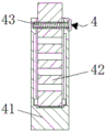
fig. 2 is a schematic view of the telescopic mechanism of the present invention.
In the figure: the yarn guide device comprises a base 1, a threaded rod 2, a threaded pipe 3, a telescopic mechanism 4, a first support rod 41, a second support rod 42, a first bolt 43, a first fixing plate 5, a second fixing plate 6, a placing groove 7, a yarn guide body 8, a first sliding block 9, a first sliding groove 10, a baffle 11, a through hole 12, a second sliding block 13, a second sliding groove 14 and a second bolt 15.
Detailed Description
The technical solutions in the embodiments of the present invention will be described clearly and completely with reference to the accompanying drawings in the embodiments of the present invention, and it is obvious that the described embodiments are only some embodiments of the present invention, not all embodiments. Based on the embodiments in the present invention, all other embodiments obtained by a person skilled in the art without creative work belong to the protection scope of the present invention.
In the description of the present invention, it is to be noted that, unless otherwise explicitly specified or limited, the terms "mounted", "provided", "connected", and the like are to be construed broadly, such as "connected", which may be fixedly connected, detachably connected, or integrally connected; can be mechanically or electrically connected; they may be connected directly or indirectly through intervening media, or they may be interconnected between two elements. The specific meaning of the above terms in the present invention can be understood in specific cases to those skilled in the art.
The utility model discloses a base 1, threaded rod 2, screwed pipe 3, telescopic machanism 4, first bracing piece 41, second bracing piece 42, first bolt 43, first fixed plate 5, second fixed plate 6, standing groove 7, yarn guide body 8, first slider 9, first spout 10, baffle 11, through-hole 12, second slider 13, second spout 14 and second bolt 15 part are general standard or the part that technical personnel in the field know, its structure and principle all are that this technical personnel all can learn through the technical manual or learn through conventional experimental method.
Referring to fig. 1-2, a yarn guide for textile machinery comprises a base 1, a baffle 11 is fixedly connected inside the base 1, and an effect of supporting a threaded rod 2 is achieved through the baffle 11, one end of the threaded rod 2 is movably connected with the baffle 11 through a bearing, a through hole 12 is formed in the top of the base 1, and a first supporting rod 41 is convenient to move through the through hole 12, the threaded rod 2 is fixedly connected to both sides of an inner cavity of the base 1, a threaded pipe 3 is sleeved on the surface of the threaded rod 2, a first sliding block 9 is fixedly connected to the bottom of the threaded pipe 3, a first sliding chute 10 is formed in the surface of the base 1, the first sliding block 9 is slidably connected with the first sliding chute 10, an effect of assisting the movement of the threaded pipe 3 is achieved through the first sliding block 9 and the first sliding chute 10, and the situation that the threaded pipe 3 is prevented from being moved too much is generated, a telescopic, the telescoping mechanism 4 comprises a first supporting rod 41, a second supporting rod 42 and a first bolt 43, the second supporting rod 42 is arranged inside the first supporting rod 41, the first bolt 43 is connected with the surface of the first supporting rod 41 in a threaded manner, the first bolt 43 is connected with the second supporting rod 42 in a threaded manner, the second slider 13 is fixedly connected with both sides of the second supporting rod 42, the second chute 14 is formed in the surface of the first supporting rod 41, the second slider 13 is connected with the second chute 14 in a sliding manner, the second sliding block 13 and the second chute 14 achieve the effect of assisting the second supporting rod 42 to move, the shaking condition is avoided, the second bolt 15 is connected with the surface of the second fixing plate 6 in a threaded manner, the second bolt 15 is connected with the first fixing plate 5 in a threaded manner, the effect of fixing the first fixing plate 5 and the second fixing plate 6 is achieved through the second bolt 15, and the falling condition of the yarn guide body 8 is avoided, the first fixed plate 5 of top fixedly connected with of second bracing piece 42, the top of first fixed plate 5 is provided with second fixed plate 6, and standing groove 7 has all been seted up to one side of first fixed plate 5 and second fixed plate 6, the inside of standing groove 7 is provided with feed carrier body 8, through setting up base 1, reach the effect of placing threaded rod 2, through threaded rod 2 and screwed pipe 3, reach the effect that drives telescopic machanism 4 and remove, through telescopic machanism 4, reach the effect to 5 altitude mixture control of first fixed plate, through first fixed plate 5, second fixed plate 6 and standing groove 7, reach the effect of placing feed carrier body 8, through feed carrier body 8, reach the effect of leading yarn, this feed carrier function is numerous, can satisfy people's demand, make things convenient for people to use.
During the use, through setting up base 1, reach the effect of placing threaded rod 2, through threaded rod 2 and screwed pipe 3, reach the effect that drives telescopic machanism 4 and remove, through telescopic machanism 4, reach the effect to 5 altitude mixture control of first fixed plate, through first fixed plate 5, second fixed plate 6 and standing groove 7, reach the effect of placing feed carrier body 8, through feed carrier body 8, reach the effect of leading the yarn, this feed carrier function is numerous, can satisfy people's demand, make things convenient for people to use.
Although embodiments of the present invention have been shown and described, it will be appreciated by those skilled in the art that changes, modifications, substitutions and alterations can be made in these embodiments without departing from the principles and spirit of the invention, the scope of which is defined in the appended claims and their equivalents.
Claims (5)
1. The utility model provides a yarn guide for textile machinery, includes base (1), its characterized in that: the yarn guide device is characterized in that threaded rods (2) are fixedly connected to two sides of an inner cavity of the base (1), a threaded pipe (3) is sleeved on the surface of each threaded rod (2), a telescopic mechanism (4) is arranged at the top of each threaded pipe (3), each telescopic mechanism (4) comprises a first supporting rod (41), a second supporting rod (42) and a first bolt (43), a first fixing plate (5) is fixedly connected to the top of each second supporting rod (42), a second fixing plate (6) is arranged at the top of each first fixing plate (5), a placing groove (7) is formed in one side of each first fixing plate (5) and one side of each second fixing plate (6), and a yarn guide body (8) is arranged inside each placing groove (7).
2. The yarn carrier for textile machinery according to claim 1, wherein: the bottom of screwed pipe (3) is fixedly connected with first slider (9), first spout (10) have been seted up on the surface of base (1), and first slider (9) and first spout (10) sliding connection.
3. The yarn carrier for textile machinery according to claim 1, wherein: the inside fixedly connected with baffle (11) of base (1), and the one end of threaded rod (2) passes through bearing and baffle (11) swing joint, through-hole (12) have been seted up at the top of base (1).
4. The yarn carrier for textile machinery according to claim 1, wherein: the support device is characterized in that a second support rod (42) is arranged inside the first support rod (41), a first bolt (43) is connected to the surface of the first support rod (41) in a threaded mode, and the first bolt (43) is connected with the second support rod (42) in a threaded mode.
5. The yarn carrier for textile machinery according to claim 1, wherein: the equal fixedly connected with second slider (13) in both sides of second bracing piece (42), second spout (14) have been seted up on the surface of first bracing piece (41), and second slider (13) and second spout (14) sliding connection, the surperficial threaded connection of second fixed plate (6) has second bolt (15), and second bolt (15) and first fixed plate (5) threaded connection.
Priority Applications (1)
| Application Number | Priority Date | Filing Date | Title |
|---|---|---|---|
| CN201921244205.9U CN210824878U (en) | 2019-08-02 | 2019-08-02 | Yarn guide for textile machinery |
Applications Claiming Priority (1)
| Application Number | Priority Date | Filing Date | Title |
|---|---|---|---|
| CN201921244205.9U CN210824878U (en) | 2019-08-02 | 2019-08-02 | Yarn guide for textile machinery |
Publications (1)
| Publication Number | Publication Date |
|---|---|
| CN210824878U true CN210824878U (en) | 2020-06-23 |
Family
ID=71268365
Family Applications (1)
| Application Number | Title | Priority Date | Filing Date |
|---|---|---|---|
| CN201921244205.9U Expired - Fee Related CN210824878U (en) | 2019-08-02 | 2019-08-02 | Yarn guide for textile machinery |
Country Status (1)
| Country | Link |
|---|---|
| CN (1) | CN210824878U (en) |
-
2019
- 2019-08-02 CN CN201921244205.9U patent/CN210824878U/en not_active Expired - Fee Related
Similar Documents
| Publication | Publication Date | Title |
|---|---|---|
| CN205772436U (en) | Yarn apparatus for correcting is used in a kind of weaving | |
| CN207932777U (en) | A kind of textile machinery yarn guide | |
| CN210824878U (en) | Yarn guide for textile machinery | |
| CN209319920U (en) | A kind of permeable breathable non-woven fabrics cutting machine | |
| CN208397184U (en) | A kind of textile machines damping device | |
| CN107021386A (en) | A kind of textile machinery bobbin | |
| CN107840187A (en) | A kind of spinning frame for being easy to place yarn bobbin | |
| CN214529390U (en) | Automatic collective doffing mechanism | |
| CN207788921U (en) | A kind of textile machinery magazine | |
| CN214879226U (en) | Textile engineering is with cone winder of conveniently changing cone winder | |
| CN206735506U (en) | A kind of safe guide cross bar | |
| CN215946338U (en) | Yarn overlapping prevention bobbin winder for combed cotton spinning | |
| CN206033978U (en) | Novel around yarn frame | |
| CN205741437U (en) | A kind of frame of textile machine device | |
| CN215557995U (en) | Yarn drum placing frame of automatic bobbin winder | |
| CN211522506U (en) | Weaving machine convenient to change syringe needle | |
| CN212175109U (en) | Supporting frame structure for textile machine | |
| CN217322838U (en) | Guide structure for electrostatic spinning yarn technology spinning | |
| CN211814785U (en) | Suspension type vaulting pole creel is used in production | |
| CN217997462U (en) | Sectional warping machine for placement | |
| CN210420305U (en) | Embedded composite spinning device | |
| CN210506622U (en) | Bobbin holder for spinning frame | |
| CN208309089U (en) | A kind of bodkin knitting needle machine | |
| CN206173517U (en) | Dust -separation device who adds bullet machine | |
| CN207837286U (en) | A kind of countable spool storing compartment for silver ion fabric |
Legal Events
| Date | Code | Title | Description |
|---|---|---|---|
| GR01 | Patent grant | ||
| GR01 | Patent grant | ||
| CF01 | Termination of patent right due to non-payment of annual fee |
Granted publication date: 20200623 Termination date: 20210802 |
|
| CF01 | Termination of patent right due to non-payment of annual fee |