CN210801830U - Quick drying equipment is used in PCB board palm ization production - Google Patents
Quick drying equipment is used in PCB board palm ization production Download PDFInfo
- Publication number
- CN210801830U CN210801830U CN201922015870.7U CN201922015870U CN210801830U CN 210801830 U CN210801830 U CN 210801830U CN 201922015870 U CN201922015870 U CN 201922015870U CN 210801830 U CN210801830 U CN 210801830U
- Authority
- CN
- China
- Prior art keywords
- box body
- motor
- box
- drying equipment
- quick drying
- Prior art date
- Legal status (The legal status is an assumption and is not a legal conclusion. Google has not performed a legal analysis and makes no representation as to the accuracy of the status listed.)
- Active
Links
Images


Classifications
-
- F—MECHANICAL ENGINEERING; LIGHTING; HEATING; WEAPONS; BLASTING
- F26—DRYING
- F26B—DRYING SOLID MATERIALS OR OBJECTS BY REMOVING LIQUID THEREFROM
- F26B21/00—Arrangements or duct systems, e.g. in combination with pallet boxes, for supplying and controlling air or gases for drying solid materials or objects
-
- F—MECHANICAL ENGINEERING; LIGHTING; HEATING; WEAPONS; BLASTING
- F26—DRYING
- F26B—DRYING SOLID MATERIALS OR OBJECTS BY REMOVING LIQUID THEREFROM
- F26B25/00—Details of general application not covered by group F26B21/00 or F26B23/00
- F26B25/06—Chambers, containers, or receptacles
- F26B25/08—Parts thereof
- F26B25/12—Walls or sides; Doors
-
- F—MECHANICAL ENGINEERING; LIGHTING; HEATING; WEAPONS; BLASTING
- F26—DRYING
- F26B—DRYING SOLID MATERIALS OR OBJECTS BY REMOVING LIQUID THEREFROM
- F26B9/00—Machines or apparatus for drying solid materials or objects at rest or with only local agitation; Domestic airing cupboards
- F26B9/06—Machines or apparatus for drying solid materials or objects at rest or with only local agitation; Domestic airing cupboards in stationary drums or chambers
-
- H—ELECTRICITY
- H05—ELECTRIC TECHNIQUES NOT OTHERWISE PROVIDED FOR
- H05K—PRINTED CIRCUITS; CASINGS OR CONSTRUCTIONAL DETAILS OF ELECTRIC APPARATUS; MANUFACTURE OF ASSEMBLAGES OF ELECTRICAL COMPONENTS
- H05K3/00—Apparatus or processes for manufacturing printed circuits
- H05K3/22—Secondary treatment of printed circuits
- H05K3/28—Applying non-metallic protective coatings
Landscapes
- Engineering & Computer Science (AREA)
- Mechanical Engineering (AREA)
- General Engineering & Computer Science (AREA)
- Manufacturing & Machinery (AREA)
- Microelectronics & Electronic Packaging (AREA)
- Drying Of Solid Materials (AREA)
Abstract
The utility model belongs to the technical field of it dries, especially, be a quick drying equipment is used in palm ization production of PCB board, be equipped with open-ended first box, bottom plate, bracing piece, lamina tecti, second motor, actuating lever, centre gripping frame, one side including top and one side and be equipped with open-ended second box, third motor, flabellum, electric heat net and automatic opening mechanism, bottom plate slidable mounting is in first box, and four bracing pieces fixed mounting that are the rectangle and distribute are at the top of bottom plate, the top of bracing piece extends to outside the first box, the bottom of lamina tecti and the top fixed connection of four bracing pieces, the bottom of lamina tecti and the top sliding connection of first box, second motor fixed mounting is at the top of lamina tecti, the actuating lever rotates to be installed on the bottom plate. The utility model discloses the knot can let whole PCB board clamping mechanism from the automatic roll-off in the stoving case to it is more convenient when installing to make the PCB board.
Description
Technical Field
The utility model relates to a stoving technical field especially relates to a PCB board palm ization production is with quick drying equipment.
Background
The PCB board is also called as a printed circuit board, is the provider of electronic components electrical connection, and in order to get rid of grease, debris etc. on the PCB board surface, the cleanliness scheduling problem of assurance face needs to palm the PCB board, and the PCB board after the palm is then need to dry, through the retrieval, the patent document of granting bulletin for CN208901781U discloses a quick drying equipment for PCB board production, including drying apparatus, stoving case and thermometer, fixed mounting has the supporting seat around the bottom of stoving case, is provided with rotary device in the middle of the bottom of stoving case, and the surface below is connected with a plurality of blast pipes about the stoving case, the fixed surface installation drying apparatus in upper surface of stoving case, and a plurality of ventilation holes have been seted up to the bottom of drying apparatus, and the round hole corresponding with the ventilation hole is seted up to the upper end of stoving case.
However, the device has the defects that the device needs to stretch into the drying box for fixing the PCB to the clamping device, so that the difficulty of fixing the PCB is increased, and the overall working efficiency is reduced.
SUMMERY OF THE UTILITY MODEL
The utility model aims at solving the defects existing in the prior art and providing a quick drying device for palm production of a PCB.
In order to achieve the above purpose, the utility model adopts the following technical scheme: a fast drying device for browning production of a PCB comprises a first box body, a bottom plate, supporting rods, a top cover plate, a second motor, a driving rod, a clamping frame, a second box body, a third motor, fan blades, an electric heating net and an automatic opening mechanism, wherein the first box body is provided with an opening at the top and one side, the second box body is provided with an opening at one side, the bottom plate is slidably mounted in the first box body, the four supporting rods distributed in a rectangular shape are fixedly mounted at the top of the bottom plate, the top ends of the supporting rods extend out of the first box body, the bottom of the top cover plate is fixedly connected with the top ends of the four supporting rods, the bottom of the top cover plate is slidably connected with the top of the first box body, the second motor is fixedly mounted at the top of the top cover plate, the driving rod is rotatably mounted on the bottom plate, the top end of the driving rod penetrates through, the second box body is fixedly arranged on one side of the first box body, the third motor is fixedly arranged on one side of the second box body, an output shaft of the third motor extends into the second box body, the fan blades are fixedly arranged on the output shaft of the third motor, the electric heating net is fixedly arranged in the second box body, and the automatic opening mechanism is arranged in the first box body; automatic opening mechanism includes the first motor of fixed mounting on first bottom half inner wall, fixed mounting has first gear on the output shaft of first motor, the internal thread pipe is installed to first box internal rotation, fixed cover is equipped with the second gear on the internal thread pipe, first gear and second gear meshing, the screw rod is installed to internal thread intraductal thread, the one end of screw rod extends to the external and fixed mounting of internal thread pipe has the baffle, one side and bottom plate fixed connection of baffle, fixed mounting has the baffle in the first box, the baffle is located the top of internal thread pipe.
Preferably, a rotating block is fixedly mounted on the inner wall of one side of the first box body, a first rotating groove is formed in the rotating block, and the internal thread pipe is rotatably connected with the first rotating groove.
Preferably, the same supporting block is fixedly installed between the first box body and the partition plate, a first rotating through hole is formed in the supporting block, and the internal thread pipe is rotatably connected with the first rotating through hole.
Preferably, the inner walls of the two sides of the first box body are provided with limiting slide rails, and the bottom plate is connected with the limiting slide rails in a sliding manner.
Preferably, a plurality of heat flow transmission holes are formed in the inner wall of one side of the first box body, a plurality of ventilation holes are formed in the inner wall of one side of the second box body, and a plurality of ventilation holes are formed in the inner walls of the two sides of the first box body.
Preferably, a box door is arranged on one side of the first box body, which is provided with an opening, and a handle is fixedly arranged on the box door.
Compared with the prior art, the beneficial effects of the utility model are that: firstly, the device is matched with a bottom plate through a first motor, a first gear, an internal thread pipe, a second gear, a screw rod, a baffle plate and a first gear, wherein the first motor drives the first gear to rotate through an output shaft, the first gear drives the internal thread pipe to rotate through the second gear, the screw rod drives the baffle plate to move towards the outside of a first box body under the action of threads, and the baffle plate brings the whole PCB clamping mechanism to the outside of the first box body through the bottom plate, so that the automatic sliding-out function of the PCB clamping mechanism is realized;
cooperate through second motor, actuating lever, centre gripping frame, third motor, flabellum and electric heat net, the second motor passes through the actuating lever and drives a plurality of centre gripping frames and rotate, and the centre gripping frame drives the PCB board and rotates, and the third motor drives the flabellum through the output shaft and rotates, and the flabellum drives the heat that the electric heat net gived off through the rotation and blows in first box by the heat flow transmission hole.
The utility model discloses the knot can let whole PCB board clamping mechanism from the automatic roll-off in the stoving case to it is more convenient when installing to make the PCB board.
Drawings
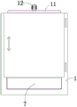
FIG. 1 is a front sectional view of the present invention;
FIG. 2 is a schematic side sectional view of the present invention;
fig. 3 is a schematic side view of the present invention.
In the figure: 1. a first case; 2. a first motor; 3. a first gear; 4. an internally threaded tube; 5. a second gear; 6. a screw; 7. a baffle plate; 8. a partition plate; 9. a base plate; 10. a support bar; 11. a top cover plate; 12. a second motor; 13. a drive rod; 14. a clamping frame; 15. a second case; 16. a third motor; 17. a fan blade; 18. an electric heating net; 19 automatic opening mechanism.
Detailed Description
The technical solutions in the embodiments of the present invention will be described clearly and completely with reference to the accompanying drawings in the embodiments of the present invention, and it is obvious that the described embodiments are only some embodiments of the present invention, not all embodiments. Based on the embodiments in the present invention, all other embodiments obtained by a person skilled in the art without creative work belong to the protection scope of the present invention.
Referring to fig. 1 to fig. 3, the present invention provides a technical solution: a fast drying device for browning production of a PCB comprises a first box body 1 with an opening on the top and one side, a bottom plate 9, support rods 10, a top cover plate 11, a second motor 12, a drive rod 13, a clamping frame 14, a second box body 15 with an opening on one side, a third motor 16, fan blades 17, an electric heating net 18 and an automatic opening mechanism 19, wherein the bottom plate 9 is slidably mounted in the first box body 1, four support rods 10 which are distributed in a rectangular shape are fixedly mounted on the top of the bottom plate 9, the top ends of the support rods 10 extend out of the first box body 1, the bottom of the top cover plate 11 is fixedly connected with the top ends of the four support rods 10, the bottom of the top cover plate 11 is slidably connected with the top of the first box body 1, the second motor 12 is fixedly mounted on the top of the top cover plate 11, the drive rod 13 is rotatably mounted on the bottom plate 9, the top end of the drive rod 13 penetrates through, a plurality of clamping frames 14 are fixedly arranged on the driving rod 13, a second box body 15 is fixedly arranged on one side of the first box body 1, a third motor 16 is fixedly arranged on one side of the second box body 15, an output shaft of the third motor 16 extends into the second box body 15, fan blades 17 are fixedly arranged on an output shaft of the third motor 16, an electric heating net 18 is fixedly arranged in the second box body 15, and an automatic opening mechanism 19 is arranged in the first box body 1; the automatic opening mechanism 19 comprises a first motor 2 fixedly installed on the inner wall of the bottom of a first box body 1, a first gear 3 is fixedly installed on an output shaft of the first motor 2, an internal threaded pipe 4 is rotatably installed in the first box body 1, a second gear 5 is fixedly sleeved on the internal threaded pipe 4, the first gear 3 is meshed with the second gear 5, a screw 6 is installed in the internal thread of the internal threaded pipe 4, one end of the screw 6 extends out of the internal threaded pipe 4 and is fixedly provided with a baffle 7, one side of the baffle 7 is fixedly connected with a bottom plate 9, a partition plate 8 is fixedly installed in the first box body 1, and the partition plate 8 is located above the internal threaded pipe 4;
a rotating block is fixedly mounted on the inner wall of one side of the first box body 1, a first rotating groove is formed in the rotating block, the internal thread pipe 4 is rotatably connected with the first rotating groove, the same supporting block is fixedly mounted between the first box body 1 and the partition plate 8, a first rotating through hole is formed in the supporting block, the internal thread pipe 4 is rotatably connected with the first rotating through hole, limiting slide rails are respectively formed in the inner walls of the two sides of the first box body 1, the bottom plate 9 is slidably connected with the limiting slide rails, a plurality of heat flow transmission holes are formed in the inner wall of one side of the first box body 1, a plurality of vent holes are formed in the inner wall of one side of the second box body 15, a plurality of vent holes are respectively formed in the inner walls of the two sides of the first box body 1, a box door is arranged on one side of the first box body 1, a handle is fixedly mounted on the box door, and passes through, The baffle 7 is matched with the bottom plate 9, the first motor 2 drives the first gear 3 to rotate through an output shaft, the first gear 3 drives the internal threaded pipe 4 to rotate through the second gear 5, the screw 6 drives the baffle 7 to move towards the outside of the first box body 1 under the action of threads, the baffle 7 drives the whole PCB clamping mechanism to the outside of the first box body 1 through the bottom plate 9, so that the automatic sliding-out function of the PCB clamping mechanism is realized, the second motor 12, the driving rod 13, the clamping frames 14, the third motor 16, the fan blades 17 and the electric heating net 18 are matched, the second motor 12 drives the plurality of clamping frames 14 to rotate through the driving rod 13, the clamping frames 14 drive the PCB to rotate, the third motor 16 drives the fan blades 17 to rotate through the output shaft, the fan blades 17 drive the heat emitted by the electric heating net 18 to be blown into the first box body 1 through heat flow transmission holes through rotating, so that the drying work of the PCB is realized, the utility model discloses the knot can let whole PCB board clamping mechanism from the automatic roll-off in the stoving case to it is more convenient when installing to make the PCB board.
The working principle is as follows: the first box body 1 is provided with a reversing switch and a starting switch, the reversing switch, the first motor 2 and an external power supply are sequentially and electrically connected through a lead to form a closed loop, the starting switch, the second motor 12, the third motor 16 and the external power supply are sequentially and electrically connected through a lead to form a closed loop, when the box door is used, the box door is pulled open through a handle, then the first motor 2 is started, the first motor 2 drives the first gear 3 to rotate through an output shaft, the first gear 3 drives the internal threaded pipe 4 to rotate through the second gear 5, the screw 6 drives the baffle 7 to move towards the outside of the first box body 1 under the action of threads, the baffle 7 drives the supporting rod 10, the top cover plate 11, the second motor 12, the driving rod 13 and the clamping frame 14 to slide towards the outside of the first box body 1 through the bottom plate 9, after the whole PCB clamping mechanism slides out of the first box body 1, the PCB is fixed on the clamping frame 14, and then the PCB clamping mechanism is sent back to the first box body 1 to close, at this moment, the second motor 12, the third motor 16 and the electric heating net 18 are started, the second motor 12 drives the plurality of clamping frames 14 to rotate through the driving rod 13, the clamping frames 14 drive the PCB to rotate, the third motor 16 drives the fan blades 17 to rotate through the output shaft, the fan blades 17 drive the airflow to blow heat dissipated by the electric heating net 18 into the first box body 1 through the heat flow transmission holes through rotation, and therefore drying work of the PCB is achieved.
It should be noted that the device structure and the accompanying drawings of the present invention mainly describe the principle of the present invention, and in the technology of this design principle, the settings of the power mechanism, the power supply system, the control system, etc. of the device are not completely described, and the details of the power mechanism, the power supply system, and the control system can be clearly known on the premise that those skilled in the art understand the principle of the present invention.
The above, only be the concrete implementation of the preferred embodiment of the present invention, but the protection scope of the present invention is not limited thereto, and any person skilled in the art is in the technical scope of the present invention, according to the technical solution of the present invention and the utility model, the concept of which is equivalent to replace or change, should be covered within the protection scope of the present invention.
Claims (6)
1. The utility model provides a PCB board palm ization production is with quick drying equipment which characterized in that: comprises a first box body (1) with an opening on the top and one side, a bottom plate (9), support rods (10), a top cover plate (11), a second motor (12), a drive rod (13), a clamping frame (14), a second box body (15) with an opening on one side, a third motor (16), fan blades (17), an electric heating net (18) and an automatic opening mechanism (19), wherein the bottom plate (9) is slidably arranged in the first box body (1), the four support rods (10) which are distributed in a rectangular shape are fixedly arranged on the top of the bottom plate (9), the top ends of the support rods (10) extend out of the first box body (1), the bottom of the top cover plate (11) is fixedly connected with the top ends of the four support rods (10), the bottom of the top cover plate (11) is slidably connected with the top of the first box body (1), the second motor (12) is fixedly arranged on the top of the top cover plate (11), the driving rod (13) is rotatably installed on the bottom plate (9), the top end of the driving rod (13) penetrates through the top cover plate (11) and is fixedly connected with an output shaft of the second motor (12), the clamping frames (14) are fixedly installed on the driving rod (13), the second box body (15) is fixedly installed on one side of the first box body (1), the third motor (16) is fixedly installed on one side of the second box body (15), the output shaft of the third motor (16) extends into the second box body (15), the fan blades (17) are fixedly installed on the output shaft of the third motor (16), the electric heating net (18) is fixedly installed in the second box body (15), and the automatic opening mechanism (19) is installed in the first box body (1);
automatic opening mechanism (19) include first motor (2) of fixed mounting on first box (1) bottom inner wall, fixed mounting has first gear (3) on the output shaft of first motor (2), internal thread pipe (4) are installed to first box (1) internal rotation, fixed cover is equipped with second gear (5) on internal thread pipe (4), first gear (3) and second gear (5) meshing, screw rod (6) are installed to internal thread pipe (4) internal thread, the one end of screw rod (6) extends to internal thread pipe (4) outer and fixed mounting have baffle (7), one side and bottom plate (9) fixed connection of baffle (7), fixed mounting has baffle (8) in first box (1), baffle (8) are located the top of internal thread pipe (4).
2. The quick drying equipment for browning production of the PCB board of claim 1, wherein the quick drying equipment comprises: the inner wall of one side of the first box body (1) is fixedly provided with a rotating block, a first rotating groove is formed in the rotating block, and the internal thread pipe (4) is rotatably connected with the first rotating groove.
3. The quick drying equipment for browning production of the PCB board of claim 1, wherein the quick drying equipment comprises: the novel box is characterized in that the same supporting block is fixedly installed between the first box body (1) and the partition plate (8), a first rotating through hole is formed in the supporting block, and the internal thread pipe (4) is rotatably connected with the first rotating through hole.
4. The quick drying equipment for browning production of the PCB board of claim 1, wherein the quick drying equipment comprises: limiting slide rails are arranged on the inner walls of the two sides of the first box body (1), and the bottom plate (9) is connected with the limiting slide rails in a sliding mode.
5. The quick drying equipment for browning production of the PCB board of claim 1, wherein the quick drying equipment comprises: a plurality of heat flow transmission holes are formed in the inner wall of one side of the first box body (1), a plurality of ventilation holes are formed in the inner wall of one side of the second box body (15), and a plurality of ventilation holes are formed in the inner walls of the two sides of the first box body (1).
6. The quick drying equipment for browning production of the PCB board of claim 1, wherein the quick drying equipment comprises: a box door is arranged on one side, provided with an opening, of the first box body (1), and a handle is fixedly mounted on the box door.
Priority Applications (2)
| Application Number | Priority Date | Filing Date | Title |
|---|---|---|---|
| CN201922015870.7U CN210801830U (en) | 2019-11-21 | 2019-11-21 | Quick drying equipment is used in PCB board palm ization production |
| PCT/CN2019/123779 WO2021097947A1 (en) | 2019-11-21 | 2019-12-06 | Rapid drying device for pcb browning production |
Applications Claiming Priority (1)
| Application Number | Priority Date | Filing Date | Title |
|---|---|---|---|
| CN201922015870.7U CN210801830U (en) | 2019-11-21 | 2019-11-21 | Quick drying equipment is used in PCB board palm ization production |
Publications (1)
| Publication Number | Publication Date |
|---|---|
| CN210801830U true CN210801830U (en) | 2020-06-19 |
Family
ID=71232532
Family Applications (1)
| Application Number | Title | Priority Date | Filing Date |
|---|---|---|---|
| CN201922015870.7U Active CN210801830U (en) | 2019-11-21 | 2019-11-21 | Quick drying equipment is used in PCB board palm ization production |
Country Status (2)
| Country | Link |
|---|---|
| CN (1) | CN210801830U (en) |
| WO (1) | WO2021097947A1 (en) |
Cited By (4)
| Publication number | Priority date | Publication date | Assignee | Title |
|---|---|---|---|---|
| CN112497460A (en) * | 2020-11-28 | 2021-03-16 | 德清科邦晶体纤维有限公司 | Novel polycrystal mullite fiberboard drying machine capable of drying uniformly |
| CN112888189A (en) * | 2021-01-14 | 2021-06-01 | 赣州邦德电路科技有限公司 | Hot-blast device that weathers of circuit board |
| CN113237304A (en) * | 2021-05-22 | 2021-08-10 | 奥士康科技股份有限公司 | Efficient drying equipment is used in PCB board production |
| CN113654310A (en) * | 2021-09-22 | 2021-11-16 | 杭州万乐电力器材有限公司 | Galvanizing process and drying equipment |
Family Cites Families (5)
| Publication number | Priority date | Publication date | Assignee | Title |
|---|---|---|---|---|
| GB1444464A (en) * | 1974-01-23 | 1976-07-28 | Bacon Bro Enterprise Co Ltd | Clothes drying apparatus |
| DE102007016255B4 (en) * | 2006-04-28 | 2012-11-29 | Bühler Motor GmbH | rotary pump |
| CN109392255B (en) * | 2018-12-06 | 2024-01-19 | 奥士康科技股份有限公司 | PCB product copper billet brown ization is with processing tool and deposit car thereof |
| CN209579473U (en) * | 2018-12-14 | 2019-11-05 | 奥士康科技股份有限公司 | Multi-station working bench for pcb board potting component |
| CN109382803A (en) * | 2018-12-14 | 2019-02-26 | 奥士康科技股份有限公司 | A kind of Multi-station working bench for pcb board potting component |
-
2019
- 2019-11-21 CN CN201922015870.7U patent/CN210801830U/en active Active
- 2019-12-06 WO PCT/CN2019/123779 patent/WO2021097947A1/en active Application Filing
Cited By (5)
| Publication number | Priority date | Publication date | Assignee | Title |
|---|---|---|---|---|
| CN112497460A (en) * | 2020-11-28 | 2021-03-16 | 德清科邦晶体纤维有限公司 | Novel polycrystal mullite fiberboard drying machine capable of drying uniformly |
| CN112497460B (en) * | 2020-11-28 | 2023-08-22 | 德清科邦晶体纤维有限公司 | Novel polycrystalline mullite fiber board dryer capable of achieving uniform drying |
| CN112888189A (en) * | 2021-01-14 | 2021-06-01 | 赣州邦德电路科技有限公司 | Hot-blast device that weathers of circuit board |
| CN113237304A (en) * | 2021-05-22 | 2021-08-10 | 奥士康科技股份有限公司 | Efficient drying equipment is used in PCB board production |
| CN113654310A (en) * | 2021-09-22 | 2021-11-16 | 杭州万乐电力器材有限公司 | Galvanizing process and drying equipment |
Also Published As
| Publication number | Publication date |
|---|---|
| WO2021097947A1 (en) | 2021-05-27 |
Similar Documents
| Publication | Publication Date | Title |
|---|---|---|
| CN210801830U (en) | Quick drying equipment is used in PCB board palm ization production | |
| CN214899544U (en) | Power distribution cabinet with moisture-proof cooling function | |
| CN213026983U (en) | Low-voltage power distribution cabinet with heat dissipation dehumidification function for community | |
| CN218770749U (en) | High-performance dehumidification and heat dissipation distribution box | |
| CN211719976U (en) | Intelligent automatic dehumidification low-voltage cabinet | |
| CN207948006U (en) | A kind of automatic welding power supply | |
| CN208047041U (en) | A kind of telecommunications equipment cabinet being easily installed | |
| CN216055783U (en) | Heat dissipation dehumidification high-low voltage power distribution cabinet | |
| CN114585229A (en) | Electric cabinet with dehumidification function and use method thereof | |
| CN210327422U (en) | Low pressure variable frequency control cabinet with two heat radiation structure | |
| CN210958205U (en) | Soft starter convenient for heat dissipation | |
| CN211655515U (en) | Electric control cabinet for electric power system | |
| CN112993780A (en) | Low-voltage switch cabinet capable of automatically radiating heat | |
| CN221467144U (en) | PLC switch board with circulation ventilation structure | |
| CN210958276U (en) | Photovoltaic microgrid is with high-efficient heat radiation structure of intelligent collection flow box | |
| CN213780764U (en) | Energy-saving and environment-friendly dehumidification device applied to electrical equipment box body | |
| CN219591906U (en) | Low-voltage switch cabinet with wiring structure | |
| CN212182931U (en) | Electric power cabinet that heat dissipation is good | |
| CN213520960U (en) | High-efficient radiating switch board | |
| CN211831679U (en) | Intelligent control device for electricity | |
| CN216215301U (en) | Block terminal with heat abstractor | |
| CN220857408U (en) | Switch cabinet | |
| CN214313939U (en) | Industrial switch board of inner space adjustable | |
| CN221080770U (en) | Novel parallel direct current power supply screen | |
| CN220401250U (en) | Low-voltage switch cabinet |
Legal Events
| Date | Code | Title | Description |
|---|---|---|---|
| GR01 | Patent grant | ||
| GR01 | Patent grant |