CN210788779U - Die stamping device - Google Patents
Die stamping device Download PDFInfo
- Publication number
- CN210788779U CN210788779U CN201921827127.5U CN201921827127U CN210788779U CN 210788779 U CN210788779 U CN 210788779U CN 201921827127 U CN201921827127 U CN 201921827127U CN 210788779 U CN210788779 U CN 210788779U
- Authority
- CN
- China
- Prior art keywords
- base
- chuck
- stamping
- vertical rods
- die
- Prior art date
- Legal status (The legal status is an assumption and is not a legal conclusion. Google has not performed a legal analysis and makes no representation as to the accuracy of the status listed.)
- Expired - Fee Related
Links
Images
Abstract
The utility model discloses a die stamping device, which comprises a base, a chuck, a cross beam and a stamping module, wherein the base is a cuboid, the base is horizontally placed, and slide rails are arranged on the left side and the right side of the upper surface of the base along the front-back direction; the chuck is placed on the base; the cross beam consists of a cross rod and symmetrically arranged vertical rods, the vertical rods are positioned in the slide rails, and the left end and the right end of the cross rod are connected with the tops of the vertical rods; the stamping module is arranged on the cross beam; the crossbeam drives the motion of punching press module during operation, can carry out the punching press to the mould pertinence, improves the accuracy and the punching press efficiency of mould punching press.
Description
Technical Field
The utility model relates to a relevant technical field of stamping die especially relates to a mould stamping device.
Background
Since the reform was open, with the rapid development of national economy, the demand of the market for molds is increasing. In recent years, the mold industry has been rapidly developed at an increasing rate of about fifteen percent, all the components of mold industry enterprises have been changed greatly, and except for national professional mold factories, the mold industry has been rapidly developed for collective, joint-investment, sole-funding and private use. "the land of the mold" in Zhejiang Ningbo and Huang Yan; the large group companies in Guangdong and the rapidly rising village and town enterprises, such as Kelong, Mei, Kangjia and the like, establish own mold manufacturing centers in a dispute; there are thousands of mould enterprises with both Chinese and foreign joint and foreign exclusive resources. With the increasing pace of international tracking and the increasing competition in the market, the importance of product quality, cost and new product development capacity has become more and more recognized. And mold manufacturing is one of the most fundamental elements in the overall chain. Many mold enterprises have increased investment efforts for technological advancement in recent years, and the technological advancement is regarded as an important driving force for enterprise development.
The height of the mold design and manufacturing technology level is one of the important marks for measuring the height of the national product manufacturing level, and determines the quality and the benefit of the product and the development capability of a new product to a great extent. The stamping die in the prior art has a single functional structure, cannot perform targeted stamping on the die, sometimes reduces the working efficiency of a stamping machine, and hinders the progress of an industrial production process.
SUMMERY OF THE UTILITY MODEL
Based on the technical problem that the background art exists, the utility model provides a mould stamping device carries out the punching press to the work piece pertinence, improves the accuracy of punching press, and then accelerates industrial production process.
The utility model provides a die stamping device, which comprises a base, a chuck, a cross beam and a stamping module, wherein the base is a cuboid, the base is horizontally placed, and slide rails are arranged on the left side and the right side of the upper surface of the base along the front-back direction; the chuck is placed on the base; the transverse beam consists of a transverse rod and symmetrically arranged vertical rods, the vertical rods are positioned in the sliding rails, and the left end and the right end of the transverse rod are connected with the tops of the vertical rods; the stamping module is arranged on the cross beam.
Further, the punching module comprises an air cylinder and a punch, the air cylinder is mounted on the cross beam, and a piston rod of the air cylinder is vertically connected with the punch downwards.
Further, the punch is detachably connected to the bottom of the piston rod.
Furthermore, the die stamping device also comprises a control panel which controls the cross beam to slide back and forth along the slide rail and controls the piston rod of the air cylinder to move up and down.
Further, the chuck is one of a three-jaw chuck or a four-jaw chuck.
The utility model provides a pair of mould stamping device's advantage lies in: the utility model provides a die stamping device in the structure, simple structure, convenient operation, through setting up the crossbeam and driving the stamping module motion, can carry out the punching press to the mould pertinence, improve the accuracy and the punching press efficiency of mould punching press; the piston rod of the air cylinder is detachably connected with the punch, so that different punching purposes and effects can be achieved by replacing punches with different shapes, and the application range of the die punching device is expanded; the workpiece is clamped by the chuck arranged on the base, so that the workpiece is prevented from moving, and the stamping accuracy is improved; through the control panel who sets up control crossbeam and cylinder, improve the control efficiency to punching press work.
Drawings
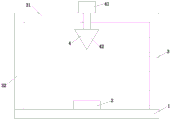
Fig. 1 is a schematic structural view of a die stamping device according to the present invention;
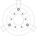
FIG. 2 is a schematic structural view of a three-jaw chuck;
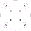
FIG. 3 is a schematic view of a four-jaw chuck;
the punching machine comprises a base 1, a base 2, a chuck 3, a cross beam 4, a punching module 31, a cross rod 32, a vertical rod 41, a cylinder 42 and a punch.
Detailed Description
As shown in fig. 1, fig. 1 is the utility model discloses a die stamping device carries out the punching press to the work piece pertinence, improves the accuracy of punching press, and then accelerates industrial production process.
Referring to fig. 1, 2 and 3, the utility model provides a die stamping device, including base 1, chuck 2, crossbeam 3 and stamping module 4, base 1 is the cuboid, and base 1 is placed horizontally, and the left and right sides of base 1 upper surface sets up the slide rail along the fore-and-aft direction, and base 1 provides the place for the punching press of mould; the chuck 2 is placed on the base 1, and the chuck 2 is used for clamping a die on the base 1; the transverse beam 3 consists of a transverse rod 31 and symmetrically arranged vertical rods 32, the vertical rods 32 are positioned in the sliding rails, the left end and the right end of the transverse rod 31 are connected with the tops of the vertical rods 32, and the transverse beam 3 is used for driving the stamping module 4 to move; the stamping module 4 is arranged on the cross beam 3, and the stamping module 4 is used for stamping a die.
The punching module 4 comprises a cylinder 41 and a punch 42, the cylinder 41 is mounted on the beam 3, and a piston rod of the cylinder 41 is vertically connected with the punch 42 downwards. The air cylinder 41 is started, and the piston rod of the air cylinder 41 drives the punch 42 to move downwards to punch the die on the chuck 2.
The punch 42 is detachably connected to the bottom of the piston rod. The detachable connection facilitates the replacement of the punch 42, and the punch 42 with different shapes can be replaced during working, so that different punching purposes and effects can be achieved.
And the control panel is used for controlling the beam 3 to slide back and forth along the slide rail and controlling the piston rod of the air cylinder 41 to move up and down. The setting of control panel more conveniently controls the punching process.
The chuck 2 is one of a three-jaw chuck or a four-jaw chuck. The three-jaw chuck is used for clamping circular regular polygonal workpieces which are integral multiples of three, and the four-jaw chuck is used for clamping various special-shaped workpieces.
In summary, the die stamping device provided in the structure of the utility model can stamp the die in a targeted manner by arranging the cross beam to drive the stamping module to move, so as to improve the accuracy and efficiency of stamping the die; the piston rod of the air cylinder is detachably connected with the punch, so that different punching purposes and effects can be achieved by replacing punches with different shapes, and the application range of the die punching device is expanded; the workpiece is clamped by the chuck arranged on the base, so that the workpiece is prevented from moving, and the stamping accuracy is improved; through the control panel who sets up control crossbeam and cylinder, improve the control efficiency to punching press work.
The above, only be the concrete implementation of the preferred embodiment of the present invention, but the protection scope of the present invention is not limited thereto, and any person skilled in the art is in the technical scope of the present invention, according to the technical solution of the present invention and the utility model, the concept of which is equivalent to replace or change, should be covered within the protection scope of the present invention.
Claims (5)
1. The die stamping device is characterized by comprising a base (1), a chuck (2), a cross beam (3) and a stamping module (4), wherein the base (1) is a cuboid, the base (1) is horizontally placed, and sliding rails are arranged on the left side and the right side of the upper surface of the base (1) along the front-back direction; the chuck (2) is placed on the base (1); the transverse beam (3) consists of a transverse rod (31) and symmetrically arranged vertical rods (32), the vertical rods (32) are positioned in the sliding rails, and the left end and the right end of the transverse rod (31) are connected with the tops of the vertical rods (32); the stamping module (4) is arranged on the cross beam (3).
2. A die stamping device according to claim 1, wherein the stamping module (4) comprises a cylinder (41) and a punch (42), the cylinder (41) being mounted on the cross beam (3), the piston rod of the cylinder (41) being connected vertically downwards to the punch (42).
3. A die stamping apparatus as claimed in claim 2, wherein the punch (42) is removably attached to the bottom of the piston rod.
4. A die stamping apparatus as claimed in claim 1 or 2, further comprising a control panel for controlling the cross member (3) to slide back and forth along the slide rail and the piston rod of the cylinder (41) to move up and down.
5. A die stamping apparatus as claimed in claim 1, wherein the chuck (2) is one of a three-jaw chuck or a four-jaw chuck.
Priority Applications (1)
| Application Number | Priority Date | Filing Date | Title |
|---|---|---|---|
| CN201921827127.5U CN210788779U (en) | 2019-10-26 | 2019-10-26 | Die stamping device |
Applications Claiming Priority (1)
| Application Number | Priority Date | Filing Date | Title |
|---|---|---|---|
| CN201921827127.5U CN210788779U (en) | 2019-10-26 | 2019-10-26 | Die stamping device |
Publications (1)
| Publication Number | Publication Date |
|---|---|
| CN210788779U true CN210788779U (en) | 2020-06-19 |
Family
ID=71237149
Family Applications (1)
| Application Number | Title | Priority Date | Filing Date |
|---|---|---|---|
| CN201921827127.5U Expired - Fee Related CN210788779U (en) | 2019-10-26 | 2019-10-26 | Die stamping device |
Country Status (1)
| Country | Link |
|---|---|
| CN (1) | CN210788779U (en) |
-
2019
- 2019-10-26 CN CN201921827127.5U patent/CN210788779U/en not_active Expired - Fee Related
Similar Documents
| Publication | Publication Date | Title |
|---|---|---|
| CN202498134U (en) | Side hole bidirectional punching die | |
| CN210788779U (en) | Die stamping device | |
| CN206567395U (en) | A kind of side piercing die of automobile engine reinforcer | |
| CN216780111U (en) | Multi-station stamping die production line | |
| CN214601461U (en) | Metal product processing stamping platform | |
| CN214263489U (en) | Full-automatic pneumatic punching machine | |
| CN208276102U (en) | Automatic impact forging equipment | |
| CN208292229U (en) | Automatic blanking device | |
| CN202479306U (en) | Full-automatic material remover | |
| CN220611979U (en) | Stamping forming equipment for hardware processing | |
| CN205128727U (en) | Platform device is hung to drift | |
| CN213798285U (en) | Hardware mould convenient to get mould | |
| CN209049950U (en) | A kind of high velocity ram machine mold | |
| CN210788771U (en) | Novel press machine | |
| CN220739150U (en) | Stamping device is used in metal product production | |
| CN206794565U (en) | A kind of automatic fixer for materiel machining | |
| CN213500943U (en) | Hot riveting type plastic welding machine capable of rapidly replacing die | |
| CN216175783U (en) | Automobile support forming and processing die | |
| CN217964590U (en) | High-rigidity positioning device for shaft machining | |
| CN218425115U (en) | Workpiece inclined hole stamping die and workpiece inclined hole stamping machine using same | |
| CN217942469U (en) | Semiconductor device positioning press-fitting mechanism | |
| CN210907725U (en) | Hardware mould of crashproof for five metals production | |
| CN217862760U (en) | Novel automatic rubbing machine | |
| CN212525663U (en) | Production device of casing | |
| CN218638326U (en) | High-efficient stamping die for punching a hole |
Legal Events
| Date | Code | Title | Description |
|---|---|---|---|
| GR01 | Patent grant | ||
| GR01 | Patent grant | ||
| CF01 | Termination of patent right due to non-payment of annual fee |
Granted publication date: 20200619 Termination date: 20211026 |
|
| CF01 | Termination of patent right due to non-payment of annual fee |