CN210771644U - Aluminum substrate LED lamp for exhibition stand - Google Patents
Aluminum substrate LED lamp for exhibition stand Download PDFInfo
- Publication number
- CN210771644U CN210771644U CN201921759882.4U CN201921759882U CN210771644U CN 210771644 U CN210771644 U CN 210771644U CN 201921759882 U CN201921759882 U CN 201921759882U CN 210771644 U CN210771644 U CN 210771644U
- Authority
- CN
- China
- Prior art keywords
- aluminum substrate
- led lamp
- baffle
- spring
- center
- Prior art date
- Legal status (The legal status is an assumption and is not a legal conclusion. Google has not performed a legal analysis and makes no representation as to the accuracy of the status listed.)
- Expired - Fee Related
Links
Images


Landscapes
- Non-Portable Lighting Devices Or Systems Thereof (AREA)
Abstract
The utility model discloses an aluminum substrate LED lamp for exhibition stand, which comprises an aluminum substrate body, LED lamp beads, a ballast body, fixing lugs, a baffle plate, a first nut sleeve, a threaded hole, a second nut sleeve, a threaded rod, a top plate, a sponge pad, a reinforcing plate, a clamping block and a rotating shaft, wherein a plurality of LED lamp beads are arranged on the surface of the aluminum substrate body, the ballast body is arranged at the center of the back part of the aluminum substrate body, a plurality of fixing lugs are fixed on the back part of the aluminum substrate body through screws, a rotating shaft is welded at one side of the top part of each fixing lug, a rotating gear is sleeved outside the rotating shaft and is positioned at one side of each fixing lug, the aluminum substrate LED lamp for exhibition stand has simple structure and convenient operation, and abandons the traditional screw fixing structure, and utilizes the clamping fixing mode that the top plate clamps a fixing beam of the exhibition stand through screwing the first nut sleeve and, and the installation and the disassembly are convenient, the maintenance and the replacement are convenient for users, and the use by the users is facilitated.
Description
Technical Field
The utility model relates to an aluminium base board LED lamp technical field specifically is an aluminium base board LED lamp for stand.
Background
The aluminum substrate LED lamp is composed of a metal-based copper-clad plate with a good heat dissipation function and an LED lamp, wherein an aluminum substrate common single-sided plate is composed of three layers of structures, namely a circuit layer, an insulating layer and a metal base layer; the LED lamp has a front surface and a back surface, wherein the white surface is welded with LED pins, the other surface presents the natural color of aluminum, and the LED lamp is generally coated with heat conducting slurry and then is contacted with a heat conducting part and is generally used for illumination of a display stand; the aluminium base board LED lamp of tradition directly adopts the screw fixation on the stand, and the screw fixation is troublesome, and is difficult to the installation and dismantles, is unfavorable for the user to maintain and changes aluminium base board LED lamp, and traditional screw fixation can't adjust aluminium base board LED lamp light illumination angle simultaneously, very easily causes the showpiece to shine incompletely, influences the showpiece exhibition, and to these defects, it is very necessary to design an aluminium base board LED lamp for the stand.
Disclosure of Invention
An object of the utility model is to provide an aluminium base board LED lamp for stand to solve the problem that proposes among the above-mentioned background art.
In order to solve the technical problem, the utility model provides a following technical scheme: an aluminum substrate LED lamp for a display stand comprises an aluminum substrate body, LED lamp beads, a ballast body, fixing lugs, a baffle plate, a first nut sleeve, a threaded hole, a second nut sleeve, a threaded rod, a top plate, a sponge pad, a non-slip pad, a rotating gear, a connecting rod, a pull disc, a pull rod, a central hole, a baffle plate, a first spring sleeve, a compression spring, a second spring sleeve, a reinforcing plate, a clamping block and a rotating shaft, wherein the surface of the aluminum substrate body is provided with a plurality of LED lamp beads, the center of the back of the aluminum substrate body is provided with the ballast body, the back of the aluminum substrate body is fixed with a plurality of fixing lugs through screws, one side of the tops of the fixing lugs is welded with a rotating shaft, the outer side of the rotating shaft is sleeved with a rotating gear, the rotating gear is positioned on one side of the fixing lugs, the center of, the baffle plate comprises a baffle plate, a pull rod, a central hole, a pull disc, a compression spring, a connecting rod and a threaded rod, wherein the pull rod is arranged at the center of the baffle plate, the central hole is sleeved outside the pull rod, one end of the pull rod is welded with the pull disc, the pull disc is positioned at one side of the baffle plate, the other end of the pull rod is welded with a reinforcing plate, one end of the reinforcing plate is positioned at the two sides of the center, the two sides of the center are both welded with second spring sleeves, one end of the second spring sleeve is sleeved with the compression spring, the compression spring is positioned at the two sides of the pull rod, one end of the compression spring is sleeved with the first spring sleeve, one end of the compression spring is connected with the first spring sleeve, one end of the first spring sleeve is connected with the baffle plate, one end of the reinforcing, and first nut cover is located baffle one side, the threaded rod other end has cup jointed second nut cover, and second nut cover is located the baffle opposite side, the welding of the threaded rod other end has the roof, and the roof is located second nut cover one side, the foam-rubber cushion has been bonded in the roof outside, the foam-rubber cushion outside has bonded the slipmat.
Furthermore, a plurality of mounting holes are formed in the bottom of the aluminum substrate body, and LED lamp beads are sleeved in the mounting holes.
Furthermore, a wire is arranged at one end of the ballast body, and one end of the wire is connected with a power supply.
Furthermore, one end of the threaded rod is welded with a blocking disc, and the blocking disc is positioned on one side of the first nut sleeve.
Furthermore, a spring groove is formed in the center of the first spring sleeve and the center of the second spring sleeve, and the spring groove is sleeved on the outer side of the compression spring.
Compared with the prior art, the utility model discloses the beneficial effect who reaches is: this aluminium base board LED lamp for stand simple structure, and convenient for operation, abandon traditional screw fixed knot structure, utilize to twist and move the tight fixed mode of clamp that first nut cover and second nut cover made the roof press from both sides tight stand fixed beam, it is fixed more firm, and the installation is dismantled conveniently, convenience of customers maintains and changes, be favorable to the user to use, adopt the pulling reel simultaneously, artifical free rotation baffle, rethread rolling gear is fixed with the fixture block chucking, can freely adjust the baffle angle and then adjust aluminium base board body angle, can change illumination angle, can freely adjust illumination angle, avoid causing the showpiece to shine incompletely because illumination angle, the showpiece angle is showpiece that greatly increases, be favorable to the showpiece exhibition.
Drawings
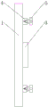
Fig. 1 is a schematic view of the overall structure of the present invention.
Fig. 2 is a rear view of the overall structure of the present invention.
Fig. 3 is a side view of the overall structure of the present invention.
Fig. 4 is an enlarged view of the baffle of the present invention.
Fig. 5 is an enlarged view of a part of the fixing lug of the present invention.
Fig. 6 is an enlarged view of a part of the separator of the present invention.
In the figure: 1. an aluminum substrate body; 2. LED lamp beads; 3. a ballast body; 4. fixing the ear; 5. a baffle plate; 6. a catch tray; 7. a first nut sleeve; 8. a threaded hole; 9. a second nut sleeve; 10. a threaded rod; 11. a top plate; 12. a sponge cushion; 13. a non-slip mat; 14. a rotating gear; 15. a connecting rod; 16. pulling the disc; 17. a pull rod; 18. a central bore; 19. a partition plate; 20. a first spring housing; 21. a compression spring; 22. a second spring housing; 23. a reinforcing plate; 24. a clamping block; 25. a rotating shaft.
Detailed Description
The technical solutions in the embodiments of the present invention will be described clearly and completely with reference to the accompanying drawings in the embodiments of the present invention, and it is obvious that the described embodiments are only some embodiments of the present invention, not all embodiments. Based on the embodiments in the present invention, all other embodiments obtained by a person skilled in the art without creative work belong to the protection scope of the present invention.
Referring to fig. 1-6, the present invention provides a technical solution: an aluminum substrate LED lamp for a display stand comprises an aluminum substrate body 1, LED lamp beads 2, a ballast body 3, fixing lugs 4, a baffle plate 5, a baffle plate 6, a first nut sleeve 7, a threaded hole 8, a second nut sleeve 9, a threaded rod 10, a top plate 11, a sponge pad 12, an anti-slip pad 13, a rotating gear 14, a connecting rod 15, a pull disc 16, a pull rod 17, a central hole 18, a partition plate 19, a first spring sleeve 20, a compression spring 21, a second spring sleeve 22, a reinforcing plate 23, a clamping block 24 and a rotating shaft 25, wherein the surface of the aluminum substrate body 1 is provided with a plurality of LED lamp beads 2, the bottom of the aluminum substrate body 1 is provided with a plurality of mounting holes, the LED lamp beads 2 are sleeved in the mounting holes, the LED lamp beads 2 are favorably fixed, the ballast body 3 is arranged at the center of the back of the aluminum substrate body 1, one end of the ballast body 3 is provided with a lead, one, the back of the aluminum substrate body 1 is fixed with a plurality of fixing lugs 4 through screws, one side of the top of each fixing lug 4 is welded with a rotating shaft 25, the outer side of the rotating shaft 25 is sleeved with a rotating gear 14, the rotating gear 14 is positioned on one side of each fixing lug 4, a partition plate 19 is fixed at the center of the bottom of each fixing lug 4 through screws, a central hole 18 is formed in the center of the partition plate 19, a pull rod 17 is arranged at the center of the partition plate 19, the central hole 18 is sleeved on the outer side of the pull rod 17, one end of the pull rod 17 is welded with a pull disc 16, the pull disc 16 is positioned on one side of the partition plate 19, the other end of the pull rod 17 is welded with a reinforcing plate 23, one end of the reinforcing plate 23 is positioned on two sides of the center, and is welded with second spring sleeves 22, one end of each second spring sleeve 22 is sleeved with a compression spring 21, the compression springs 21 are positioned on two sides of the pull rod 17, one end, and the spring groove is sleeved outside the compression spring 21, which is beneficial to fixing the compression spring 21, one end of the reinforcing plate 23 is welded with a fixture block 24, the fixture block 24 is positioned at one side of the rotating gear 14, the other side of the rotating gear 14 is welded with a connecting rod 15, one end of the connecting rod 15 is fixed with a baffle 5 through a screw, the baffle 5 is positioned at one side of the fixing lug 4, the center of the baffle 5 is provided with a threaded hole 8, the center of the baffle 5 is provided with a threaded rod 10, the threaded rod 10 is positioned inside the threaded hole 8, one end of the threaded rod 10 is sleeved with a first nut sleeve 7, the first nut sleeve 7 is positioned at one side of the baffle 5, one end of the threaded rod 10 is welded with a baffle disc 6, the baffle disc 6 is positioned at one side of the first nut sleeve 7, which is beneficial to fixing the threaded rod 10, the other end, the top plate 11 is positioned on one side of the second nut sleeve 9, a spongy cushion 12 is bonded on the outer side of the top plate 11, and an anti-skid cushion 13 is bonded on the outer side of the spongy cushion 12; when the aluminum substrate LED lamp for the exhibition stand is used, the top plates 11 on two sides of the top of the aluminum substrate body 1 are manually clamped on the exhibition stand fixing beam, the first nut sleeve 7 and the second nut sleeve 9 are rotated clockwise, the first nut sleeve 7 and the second nut sleeve 9 drive the threaded rod 10 to move, the threaded rod 10 extrudes the top plate 11 to enable the top plate 11 to clamp the exhibition stand fixing beam, the second nut sleeve 9 is rotated anticlockwise to enable the first nut sleeve 7 and the second nut sleeve 9 to clamp the baffle 5 to finish fixing, meanwhile, the pull disc 16 is manually pulled, the pull disc 16 drives the pull rod 17 to move, the pull rod 17 drives the fixture block 24 to move, the fixture block 24 extrudes the compression spring 21, the compression spring 21 contracts to have elastic force, at the moment, the baffle 5 is manually rotated to drive the rotating gear 14 to rotate, the pull disc 16 is loosened until the baffle 5 is adjusted to a proper position, the compression spring 21 stretches back to enable the fixture block 24 to be clamped, baffle 5 can fix the position, connects ballast body 3 with the power, and LED lamp pearl 2 can throw light on.
It is noted that, herein, relational terms such as first and second, and the like may be used solely to distinguish one entity or action from another entity or action without necessarily requiring or implying any actual such relationship or order between such entities or actions. Also, the terms "comprises," "comprising," or any other variation thereof, are intended to cover a non-exclusive inclusion, such that a process, method, article, or apparatus that comprises a list of elements does not include only those elements but may include other elements not expressly listed or inherent to such process, method, article, or apparatus.
Finally, it should be noted that: although the present invention has been described in detail with reference to the foregoing embodiments, it will be apparent to those skilled in the art that modifications may be made to the embodiments described in the foregoing embodiments, or equivalents may be substituted for elements thereof. Any modification, equivalent replacement, or improvement made within the spirit and principle of the present invention should be included in the protection scope of the present invention.
Claims (5)
1. The utility model provides an aluminium base board LED lamp for stand, including aluminium base board body (1), LED lamp pearl (2), ballast body (3), fixed ear (4), baffle (5), fender dish (6), first nut cover (7), screw hole (8), second nut cover (9), threaded rod (10), roof (11), foam-rubber cushion (12), slipmat (13), rolling gear (14), connecting rod (15), disc (16), pull rod (17), centre bore (18), baffle (19), first spring housing (20), compression spring (21), second spring housing (22), reinforcing plate (23), fixture block (24) and pivot (25), its characterized in that: the LED lamp comprises an aluminum substrate body (1), a plurality of LED lamp beads (2) are arranged on the surface of the aluminum substrate body (1), a ballast body (3) is arranged at the center of the back of the aluminum substrate body (1), a plurality of fixing lugs (4) are fixed on the back of the aluminum substrate body (1) through screws, a rotating shaft (25) is welded on one side of the tops of the fixing lugs (4), a rotating gear (14) is sleeved on the outer side of the rotating shaft (25), the rotating gear (14) is located on one side of the fixing lugs (4), a partition plate (19) is fixed on the center of the bottom of each fixing lug (4) through screws, a central hole (18) is formed in the center of the partition plate (19), a pull rod (17) is arranged at the center of the partition plate (19), the central hole (18) is sleeved on the outer side of the pull rod (17), a pull disc (16), the other end of the pull rod (17) is welded with a reinforcing plate (23), one end of the reinforcing plate (23) is positioned on two sides of the center and is welded with a second spring sleeve (22), one end of the second spring sleeve (22) is sleeved with a compression spring (21), the compression spring (21) is positioned on two sides of the pull rod (17), one end of the compression spring (21) is sleeved with a first spring sleeve (20), one end of the first spring sleeve (20) is connected with the partition plate (19), one end of the reinforcing plate (23) is welded with a fixture block (24), the fixture block (24) is positioned on one side of the rotating gear (14), the other side of the rotating gear (14) is welded with a connecting rod (15), one end of the connecting rod (15) is fixed with a baffle (5) through screws, the baffle (5) is positioned on one side of the fixing lug (4), the center of the baffle (5) is provided with a threaded hole (8), and the center, and threaded rod (10) are located inside screw hole (8), threaded rod (10) one end has cup jointed first nut cover (7), and first nut cover (7) are located baffle (5) one side, threaded rod (10) other end has cup jointed second nut cover (9), and second nut cover (9) are located baffle (5) opposite side, threaded rod (10) other end welding has roof (11), and roof (11) are located second nut cover (9) one side, foam-rubber cushion (12) have been bonded in roof (11) outside, foam-rubber cushion (12) outside bonding has slipmat (13).
2. The aluminum substrate LED lamp for the exhibition stand as claimed in claim 1, wherein: a plurality of mounting holes are formed in the bottom of the aluminum substrate body (1), and LED lamp beads (2) are sleeved in the mounting holes.
3. The aluminum substrate LED lamp for the exhibition stand as claimed in claim 1, wherein: one end of the ballast body (3) is provided with a wire, and one end of the wire is connected with a power supply.
4. The aluminum substrate LED lamp for the exhibition stand as claimed in claim 1, wherein: one end of the threaded rod (10) is welded with a blocking disc (6), and the blocking disc (6) is located on one side of the first nut sleeve (7).
5. The aluminum substrate LED lamp for the exhibition stand as claimed in claim 1, wherein: spring grooves are formed in the centers of the first spring sleeve (20) and the second spring sleeve (22) and are sleeved on the outer side of the compression spring (21).
Priority Applications (1)
| Application Number | Priority Date | Filing Date | Title |
|---|---|---|---|
| CN201921759882.4U CN210771644U (en) | 2019-10-21 | 2019-10-21 | Aluminum substrate LED lamp for exhibition stand |
Applications Claiming Priority (1)
| Application Number | Priority Date | Filing Date | Title |
|---|---|---|---|
| CN201921759882.4U CN210771644U (en) | 2019-10-21 | 2019-10-21 | Aluminum substrate LED lamp for exhibition stand |
Publications (1)
| Publication Number | Publication Date |
|---|---|
| CN210771644U true CN210771644U (en) | 2020-06-16 |
Family
ID=71048846
Family Applications (1)
| Application Number | Title | Priority Date | Filing Date |
|---|---|---|---|
| CN201921759882.4U Expired - Fee Related CN210771644U (en) | 2019-10-21 | 2019-10-21 | Aluminum substrate LED lamp for exhibition stand |
Country Status (1)
| Country | Link |
|---|---|
| CN (1) | CN210771644U (en) |
Cited By (1)
| Publication number | Priority date | Publication date | Assignee | Title |
|---|---|---|---|---|
| CN112739099A (en) * | 2020-12-25 | 2021-04-30 | 山东博远科技服务有限公司 | Power-off protection device for electronic information equipment |
-
2019
- 2019-10-21 CN CN201921759882.4U patent/CN210771644U/en not_active Expired - Fee Related
Cited By (1)
| Publication number | Priority date | Publication date | Assignee | Title |
|---|---|---|---|---|
| CN112739099A (en) * | 2020-12-25 | 2021-04-30 | 山东博远科技服务有限公司 | Power-off protection device for electronic information equipment |
Similar Documents
| Publication | Publication Date | Title |
|---|---|---|
| CN210771644U (en) | Aluminum substrate LED lamp for exhibition stand | |
| CN210469510U (en) | Surveillance camera head easy to assemble | |
| CN211123589U (en) | Reflector for photographic flash lamp | |
| CN209495215U (en) | A kind of low-power classroom lamp | |
| CN212809691U (en) | Outdoor light guide plate lamp box | |
| CN207865177U (en) | A kind of double light source Ceiling lights | |
| CN111649266A (en) | Light guide panel lamp with small light loss and cooling and anti-drop functions | |
| CN207621855U (en) | A kind of LED flat lamp | |
| CN201318638Y (en) | Universal mounted LED spotlight mounting seat | |
| CN215570026U (en) | Anti-dazzle LED wall washer lamp with radiating fins | |
| CN205245087U (en) | Fixing structure of panel light | |
| CN211286239U (en) | Monomer furred ceiling convenient to even illumination | |
| CN220567104U (en) | Dustproof LED down lamp | |
| CN219493948U (en) | Lamp bead structure with double-sided light-emitting function | |
| CN213272266U (en) | LED panel light fixed knot constructs | |
| CN212986985U (en) | Blackboard lamp convenient to block installation | |
| CN210267012U (en) | Special lamp of chargeable suspension type music stand | |
| CN217109316U (en) | Novel dustproof anti-dazzle LED down lamp | |
| CN214335437U (en) | Multifunctional light supplement lamp | |
| CN210704661U (en) | LED lamp panel supports doffer | |
| CN218209112U (en) | Anti-glare lens mounting structure for lamp | |
| CN212456431U (en) | Spotlight inspection lamp for obstetrics and gynecology department | |
| CN208832389U (en) | A kind of convenient mounting structure of lamps and lanterns | |
| CN214369709U (en) | Lamp convenient to install | |
| CN215446142U (en) | Lighting lamp |
Legal Events
| Date | Code | Title | Description |
|---|---|---|---|
| GR01 | Patent grant | ||
| GR01 | Patent grant | ||
| CF01 | Termination of patent right due to non-payment of annual fee |
Granted publication date: 20200616 Termination date: 20201021 |
|
| CF01 | Termination of patent right due to non-payment of annual fee |