CN210768979U - Engine respiratory system - Google Patents
Engine respiratory system Download PDFInfo
- Publication number
- CN210768979U CN210768979U CN201922007714.6U CN201922007714U CN210768979U CN 210768979 U CN210768979 U CN 210768979U CN 201922007714 U CN201922007714 U CN 201922007714U CN 210768979 U CN210768979 U CN 210768979U
- Authority
- CN
- China
- Prior art keywords
- cavity
- partition plate
- opening
- side wall
- oil
- Prior art date
- Legal status (The legal status is an assumption and is not a legal conclusion. Google has not performed a legal analysis and makes no representation as to the accuracy of the status listed.)
- Active
Links
Images


Landscapes
- Lubrication Details And Ventilation Of Internal Combustion Engines (AREA)
Abstract
The utility model belongs to the field of engines and discloses an engine breathing system, which comprises an engine body and a chamber cover, wherein a waste gas inlet is arranged on the engine body; the chamber cover is provided with a first cavity, and the chamber cover is arranged on the machine body to seal the first cavity; a first partition plate, a second partition plate and a third partition plate are sequentially arranged in the first cavity at intervals, the first partition plate and the second partition plate sequentially divide the first cavity into a labyrinth cavity, a rotational flow channel and an adsorption cavity for oil-gas separation, and the third partition plate and the side wall of the first cavity are enclosed to form an oil storage cavity; the first partition plate is provided with a first opening, and the labyrinth cavity is communicated with the rotational flow channel through the first opening; a second opening is formed in the second partition plate, the second opening is located below the first opening, and the rotational flow channel is communicated with the adsorption cavity through the second opening; and a swirl port is arranged at one end of the third clapboard close to the second opening. The utility model discloses a carry out three oil filtrations to waste gas, the machine oil that can significantly reduce exhales the volume, not only reduces the machine oil energy consumption, can reduce the pollution to the environment moreover.
Description
Technical Field
The utility model belongs to the technical field of the engine, in particular to engine respiratory.
Background
When the engine works, the waste gas generated by the combustion chamber has a part to flee to the crankcase along with the continuous reciprocating motion of the piston, if the waste gas flowing into the crankcase can not be discharged in time, the pressure in the crankcase can continuously rise to form high pressure, a large amount of leakage of engine oil in the crankcase from a sealing joint surface and an engine oil pipe can be caused, and the normal work of the engine is influenced, so that a breathing system is required to be arranged to control the pressure in the crankcase, and the pressure in the crankcase is prevented from being too high.
When the breathing system discharges gas, the discharged gas also needs to be subjected to oil-gas separation. The existing respiratory system is generally of a single labyrinth structure, so that oil and gas cannot be effectively separated, the problem of pager oil is easy to occur, the energy consumption of the engine oil is increased, and the environment is polluted.
Disclosure of Invention
The utility model aims at providing an engine respiratory solves the problem that the engine breathed machine oil to reduce machine oil energy consumption and environmental pollution.
The utility model provides a technical scheme as follows:
in one aspect, an engine breathing system is provided, comprising:
the engine body is provided with a waste gas inlet;
the chamber cover is provided with a first cavity and arranged on the machine body to seal the first cavity;
a first partition plate, a second partition plate and a third partition plate are sequentially arranged in the first cavity at intervals, the first partition plate and the second partition plate sequentially divide the first cavity into a labyrinth cavity, a cyclone channel and an adsorption cavity for oil-gas separation, and the third partition plate and the side wall of the first cavity are enclosed to form an oil storage cavity;
the first partition plate is provided with a first opening, and the labyrinth cavity is communicated with the rotational flow channel through the first opening;
a second opening is formed in the second partition plate, the second opening is located below the first opening, and the rotational flow channel is communicated with the adsorption cavity through the second opening;
a swirl port is arranged at one end of the third clapboard close to the second opening;
the labyrinth cavity is communicated with the air inlet, the adsorption cavity is provided with an air outlet, and the side wall of the oil storage cavity is provided with an oil return port.
Further preferably, the first cavity comprises a first side wall and a second side wall which are oppositely arranged;
one end of the first partition plate is arranged on the second side wall, and the other end of the first partition plate is spaced from the first side wall to form the first opening;
one end of the second partition plate is arranged on the first side wall, and the other end of the second partition plate is spaced from the second side wall to form the second opening.
Further preferably, the area of the first opening is larger than the area of the second opening.
Further preferably, the first baffle is arc-shaped;
the concave part of the first baffle plate is arranged towards the swirling flow channel.
Further preferably, a support for supporting the first partition plate is further included;
one end of the supporting piece is arranged on the second side wall, and the other end of the supporting piece is arranged at one end, far away from the second side wall, of the first partition board.
Further preferably, the second partition plate includes a vertical portion, a connecting portion, and an inclined portion;
one end of the vertical part is arranged on the first side wall, and the other end of the vertical part is connected with the inclined part through the connecting part;
the distance from one end of the inclined part connected with the connecting part to the first side wall is smaller than the distance from the other end of the inclined part to the first side wall.
Further preferably, the third partition plate is located below the adsorption chamber;
the third baffle is arc, and the convex part orientation of arc third baffle the oil storage chamber sets up.
Further preferably, the air conditioner further comprises a fourth partition plate:
the fourth partition plate is arranged in the labyrinth cavity;
the fourth clapboard divides the labyrinth cavity into a plurality of labyrinth channels.
Further preferably, a respirator is also included;
the respirator is arranged in the adsorption cavity, an exhaust pipe is arranged on the respirator, and the exhaust pipe extends out of the chamber cover through the exhaust port and is used for discharging the waste gas.
Further preferably, the chamber cover, the first cavity, the first partition, the second partition and the third partition are integrally formed; and/or the presence of a gas in the gas,
the opening of the swirl port is arranged along the tangent of the flowing direction of the waste gas.
Compared with the prior art, the utility model provides a pair of engine respiratory has following beneficial effect:
1) the utility model discloses an engine respiratory is provided with labyrinth chamber, whirl passageway and absorption chamber in, after waste gas got into respiratory, carries out first oil strain to waste gas through labyrinth chamber, then carries out second oil strain to waste gas through the whirl passageway, and the absorption chamber of last passageway carries out third oil strain to waste gas, through carrying out three oil strains to waste gas, and the machine oil that can significantly reduce exhales volume, not only reduces the machine oil energy consumption, can reduce the pollution to the environment moreover.
2) The utility model discloses utilize the combination in organism and chamber cap space, make the respirator press close to the less absorption inner chamber region of machine oil mist most, the machine oil of significantly reducing exhales volume.
3) The utility model discloses under the prerequisite in finite space, carry out integral compact structure design to maze, whirl and absorption chamber isotructure, whole respiratory system assembly has only an external respirator structure, and the structure of the assembly that significantly reduces falls this and increase.
Drawings
The above features, technical features, advantages and modes of realisation of an engine breathing system will be further described in the following, in a clearly understandable manner, with reference to the accompanying drawings, which illustrate preferred embodiments.
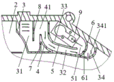
FIG. 1 is a cross-sectional view of a chamber lid of an embodiment of an engine breathing system of the present invention;
fig. 2 is a schematic structural diagram of a body of an engine breathing system of the present invention;
fig. 3 is a cross-sectional view of a chamber cover of another embodiment of an engine breathing system of the present invention.
Description of the reference numerals
1. A body; 11. an air inlet; 2. a chamber lid; 3. a first cavity; 31. a uterine cavity; 32. a swirling flow passage; 33. an adsorption chamber; 34. an oil storage chamber; 341. an oil return port; 35. a first side wall; 36. a second side wall; 4. a first separator; 41. a first opening; 5. a second separator; 51. a second opening; 52. a vertical portion; 53. a connecting portion; 54. an inclined portion; 6. a third partition plate; 61. a swirl port; 7. a support member; 8. a fourth separator; 9. a respirator; 91. a first lumen; 92. a second lumen.
Detailed Description
In order to more clearly illustrate embodiments of the present invention or technical solutions in the prior art, specific embodiments of the present invention will be described below with reference to the accompanying drawings. It is obvious that the drawings in the following description are only examples of the invention, and that for a person skilled in the art, other drawings and embodiments can be obtained from these drawings without inventive effort.
It will be understood that the terms "comprises" and/or "comprising," when used in this specification, specify the presence of stated features, integers, steps, operations, elements, and/or components, but do not preclude the presence or addition of one or more other features, integers, steps, operations, elements, components, and/or groups thereof.
For the sake of simplicity, only the parts relevant to the present invention are schematically shown in the drawings, and they do not represent the actual structure as a product. In addition, in order to make the drawings concise and understandable, components having the same structure or function in some of the drawings are only schematically illustrated or only labeled. In this document, "one" means not only "only one" but also a case of "more than one".
The embodiment of the present invention provides an engine breathing system, please refer to fig. 1 and 2, which includes a machine body 1 and a chamber cover 2; the machine body 1 is provided with a waste gas inlet 11; the first cavity 3 is arranged on the chamber cover 2, the chamber cover 2 is covered on the machine body 1, the first cavity 3 is sealed, when the chamber cover 2 is assembled with the machine body 1, a gasket can be arranged on the machine body 1 at a position opposite to the first cavity 3, and the first cavity 3 is sealed through the gasket.
A first partition plate 4, a second partition plate 5 and a third partition plate 6 are sequentially arranged in the first cavity 3 at intervals, the first cavity 3 is sequentially divided into a labyrinth cavity 31, a rotational flow channel 32 and an adsorption cavity 33 by the first partition plate 4 and the second partition plate 5, and the oil storage cavity 34 is formed by the third partition plate 6 and the side wall of the first cavity 3 in an enclosing manner;
the first partition plate 4 is provided with a first opening 41, and the labyrinth cavity 31 is communicated with the rotational flow channel 32 through the first opening 41; the second partition 5 is provided with a second opening 51, the second opening 51 is positioned below the first opening 41, and the swirling flow passage 32 is communicated with the adsorption chamber 33 through the second opening 51. The first opening 41 is an inlet of the cyclone channel 32, the second opening 51 is an outlet of the cyclone channel 32, and the second opening 51 is located below the first opening 41, so that the exhaust gas can be separated from the oil gas in the exhaust gas through centrifugal force and gravity in the cyclone channel 32.
A swirl port 61 is provided at an end of the third partition plate 6 adjacent to the second opening 51, and the engine oil separated from the exhaust gas can be introduced into the oil storage chamber 34 through the swirl port 61. The labyrinth chamber 31 is communicated with the air inlet 11, the adsorption chamber 33 is provided with an air outlet, and the side wall of the oil storage chamber 34 is provided with an oil return port 341. When the piston moves upward, the engine oil remaining in the oil storage chamber 34 can flow back to the body cavity through the oil return port 341, and the body cavity is a cavity for storing the lubricating oil in the machine body 1. More preferably, the opening of the swirl port 61 is arranged tangentially to the flow direction of the exhaust gas.
In the embodiment, the waste gas enters the labyrinth cavity 31 from the gas inlet 11 on the machine body 1, and the oil vapor in the waste gas in the labyrinth cavity 31 is adsorbed on the wall of the labyrinth cavity 31 due to condensation in the flowing process, so that the first oil filtering of the waste gas is realized; the labyrinth cavity 31 is communicated with the rotational flow channel 32, the waste gas enters the rotational flow channel 32 after passing through the labyrinth cavity 31, the engine oil particles in the waste gas are subjected to rotational filtration in the rotational flow channel 32 under the action of centrifugal force and gravity, and are thrown into the oil storage cavity 34 through the rotational flow port 61 in the tangential direction of the flow direction; a second oil filter for waste gas is formed, and the oil-gas separation efficiency is further improved in a limited space through a compact arrangement mode; the outlet of the cyclone channel 32 is communicated with the adsorption cavity 33, and after the waste gas passing through the cyclone channel 32 enters the adsorption cavity 33, the last residual small amount of engine oil particles are adsorbed and filtered again by the adsorption cavity 33 to form a third oil filter.
The utility model discloses a carry out three oil filtrations to waste gas, the machine oil that can significantly reduce exhales the volume, not only reduces the machine oil energy consumption, can reduce the pollution to the environment moreover.
In one embodiment, with continued reference to fig. 1, the first chamber 3 includes a first sidewall 35 and a second sidewall 36 oppositely disposed; one end of the first partition plate 4 is arranged on the second side wall 36, and the other end of the first partition plate 4 is spaced from the first side wall 35 to form the first opening 41, so that the labyrinth cavity 31 is communicated with the rotational flow channel 32 through the first opening 41; one end of the second partition plate 5 is disposed on the first side wall 35, and the other end of the second partition plate 5 is spaced apart from the second side wall 36 to form the above-mentioned second opening 51, so that the swirling flow path 32 is disposed in communication with the adsorption chamber 33 through the second opening 51.
In this embodiment, the first partition plate 4 and the second partition plate 5 are formed with openings communicating with each other through the other ends thereof not connected to the inner wall of the first chamber 3, respectively, and the manufacturing process can be simplified.
Preferably, the area of the first opening 41 is larger than the area of the second opening 51; the exhaust gas enters the swirling flow channel 32 from the first opening 41 with a larger area and flows out through the second opening 51 with a smaller area, so that the oil filtering effect of the swirling flow channel 32 can be improved.
The first clapboard 4 is arc-shaped; the concave portion of the arc-shaped first partition plate 4 is disposed toward the swirling flow passage 32. The first partition plate 4 is arc-shaped, so that the centrifugal force of the swirling flow channel 32 can be improved, and the oil filtering effect of the swirling flow channel 32 is further improved.
A supporting member 7 is further disposed in the first chamber 3, one end of the supporting member 7 is disposed on the second sidewall 36, and the other end of the supporting member 7 is disposed at one end of the first partition plate 4 away from the second sidewall 36. First baffle 4 is the arc, through set up support piece 7 in first baffle 4 below, can play the supporting role to first baffle 4, prevents that first baffle 4 from taking place to warp when exhaust pressure is great.
The second partition 5 includes a vertical portion 52, a connecting portion 53, and an inclined portion 54; one end of the vertical portion 52 is provided on the first side wall 35, and the other end of the vertical portion 52 is connected to the inclined portion 54 through a connecting portion 53; the distance from one end of the inclined portion 54 connected to the connection portion 53 to the first side wall 35 is smaller than the distance from the other end of the inclined portion 54 to the first side wall 35. The inclined part 54 inclines downwards, the spiral flow channel 32 with a certain radian is formed by the inclined part 54 and the arc-shaped first partition plate 4, the centrifugal force of the spiral flow channel 32 can be further improved, and the oil filtering effect of the spiral flow channel 32 is further improved.
The third partition plate 6 is positioned below the adsorption chamber 33; the third partition plate 6 has an arc shape, and a convex portion of the arc-shaped third partition plate 6 is disposed toward the reservoir chamber 34. The third partition plate 6 is arc-shaped, so that the waste gas can enter the adsorption cavity 33 from the rotational flow channel 32 for buffer transition, and the arc-shaped third partition plate 6 can increase the length of the rotational flow channel 32, so that engine oil particles in the waste gas are rotatably filtered to the oil storage cavity 34 through the rotational flow port 61, and the oil filtering effect is improved.
In one embodiment, referring to fig. 3, at least one fourth partition 8 is further disposed in the labyrinth chamber 31, and the fourth partition 8 divides the labyrinth chamber 31 into a plurality of labyrinth passages. The fourth partition plate 8 is arranged in the labyrinth cavity 31, and engine oil particles in the waste gas can be adsorbed on the inner wall of the labyrinth cavity 31 and also can be adsorbed on the fourth partition plate 8, so that the oil filtering effect of the labyrinth cavity 31 is improved.
In one embodiment, referring to fig. 1 and 3, a breather 9 is further disposed in the adsorption chamber 33, and an exhaust pipe is disposed on the breather 9 and extends out of the chamber cover 2 through the exhaust port for exhausting the exhaust gas. After the exhaust gas enters the adsorption cavity 33, a small amount of engine oil particles left in the exhaust gas are adsorbed, then the exhaust gas enters the breather 9, and the exhaust gas after oil filtration is discharged from an exhaust pipe on the breather 9 through the breather 9.
In one embodiment, the chamber lid 2, the first chamber 3, the first partition 4, the second partition 5 and the third partition 6 are integrally formed. Preferably, chamber lid 2, first cavity 3, first baffle 4, second baffle 5, third baffle 6 and the setting of the 8 integrated into one piece of fourth baffle, when chamber lid 2 shaping promptly, with the shaping of engine respiratory with chamber lid 2 together, make whole respiratory only need connect a respirator 9, but the quantity of the spare part of significantly reducing reduces purchasing cost.
It should be noted that the above embodiments can be freely combined as necessary. The foregoing is only a preferred embodiment of the present invention, and it should be noted that, for those skilled in the art, a plurality of modifications and decorations can be made without departing from the principle of the present invention, and these modifications and decorations should also be regarded as the protection scope of the present invention.
Claims (10)
1. An engine breathing system, comprising:
the engine body is provided with a waste gas inlet;
the chamber cover is provided with a first cavity and arranged on the machine body to seal the first cavity;
a first partition plate, a second partition plate and a third partition plate are sequentially arranged in the first cavity at intervals, the first partition plate and the second partition plate sequentially divide the first cavity into a labyrinth cavity, a cyclone channel and an adsorption cavity for oil-gas separation, and the third partition plate and the side wall of the first cavity are enclosed to form an oil storage cavity;
the first partition plate is provided with a first opening, and the labyrinth cavity is communicated with the rotational flow channel through the first opening;
a second opening is formed in the second partition plate, the second opening is located below the first opening, and the rotational flow channel is communicated with the adsorption cavity through the second opening;
a swirl port is arranged at one end of the third clapboard close to the second opening;
the labyrinth cavity is communicated with the air inlet, the adsorption cavity is provided with an air outlet, and the side wall of the oil storage cavity is provided with an oil return port.
2. The engine breathing system of claim 1,
the first cavity comprises a first side wall and a second side wall which are oppositely arranged;
one end of the first partition plate is arranged on the second side wall, and the other end of the first partition plate is spaced from the first side wall to form the first opening;
one end of the second partition plate is arranged on the first side wall, and the other end of the second partition plate is spaced from the second side wall to form the second opening.
3. The engine breathing system of claim 2,
the area of the first opening is larger than the area of the second opening.
4. The engine breathing system of claim 2,
the first partition plate is arc-shaped;
the concave part of the first baffle plate is arranged towards the swirling flow channel.
5. The engine breathing system of claim 4,
the support piece is used for supporting the first partition plate;
one end of the supporting piece is arranged on the second side wall, and the other end of the supporting piece is arranged at one end, far away from the second side wall, of the first partition board.
6. The engine breathing system of claim 2,
the second barrier includes a vertical portion, a connection portion, and an inclined portion;
one end of the vertical part is arranged on the first side wall, and the other end of the vertical part is connected with the inclined part through the connecting part;
the distance from one end of the inclined part connected with the connecting part to the first side wall is smaller than the distance from the other end of the inclined part to the first side wall.
7. The engine breathing system of claim 2,
the third partition plate is positioned below the adsorption cavity;
the third baffle is arc, and the convex part orientation of arc third baffle the oil storage chamber sets up.
8. The engine breathing system of claim 1,
still include the fourth baffle:
the fourth partition plate is arranged in the labyrinth cavity;
the fourth clapboard divides the labyrinth cavity into a plurality of labyrinth channels.
9. The engine breathing system of claim 1,
also comprises a respirator;
the respirator is arranged in the adsorption cavity, an exhaust pipe is arranged on the respirator, and the exhaust pipe extends out of the chamber cover through the exhaust port and is used for discharging the waste gas.
10. The engine breathing system of claim 1,
the chamber cover, the first cavity, the first clapboard, the second clapboard and the third clapboard are integrally formed; and/or the presence of a gas in the gas,
the opening of the swirl port is arranged along the tangent of the flowing direction of the waste gas.
Priority Applications (1)
| Application Number | Priority Date | Filing Date | Title |
|---|---|---|---|
| CN201922007714.6U CN210768979U (en) | 2019-11-20 | 2019-11-20 | Engine respiratory system |
Applications Claiming Priority (1)
| Application Number | Priority Date | Filing Date | Title |
|---|---|---|---|
| CN201922007714.6U CN210768979U (en) | 2019-11-20 | 2019-11-20 | Engine respiratory system |
Publications (1)
| Publication Number | Publication Date |
|---|---|
| CN210768979U true CN210768979U (en) | 2020-06-16 |
Family
ID=71038398
Family Applications (1)
| Application Number | Title | Priority Date | Filing Date |
|---|---|---|---|
| CN201922007714.6U Active CN210768979U (en) | 2019-11-20 | 2019-11-20 | Engine respiratory system |
Country Status (1)
| Country | Link |
|---|---|
| CN (1) | CN210768979U (en) |
-
2019
- 2019-11-20 CN CN201922007714.6U patent/CN210768979U/en active Active
Similar Documents
| Publication | Publication Date | Title |
|---|---|---|
| CN101498234B (en) | Crankshaft case respiration apparatus of internal-combustion engine | |
| CN101539045A (en) | Gas and oil separating plant for internal combustion engine | |
| CN108049937A (en) | Oil and gas separating system built in valve mechanism cover | |
| CN2856434Y (en) | Cyclone centrifugal breather | |
| CN206190416U (en) | Cylinder end lid and general gasoline engine thereof | |
| CN110685778A (en) | Engine respiratory system | |
| CN210768979U (en) | Engine respiratory system | |
| GB2452980A (en) | A separator | |
| CN203962099U (en) | A kind of engine breathing system and motor | |
| CN210799082U (en) | Fine separation structure of oil-gas separator of engine | |
| CN201513251U (en) | Labyrinth type valve chamber cover shell | |
| CN208106523U (en) | Crankcase ventilation system for medium-sized diesel engine | |
| CN101185919A (en) | Cyclone separating gas oil separator | |
| CN215170269U (en) | Negative pressure type oil-gas separation device | |
| CN215860389U (en) | High-efficiency oil-gas separation system and engine thereof | |
| CN214887295U (en) | Oil-gas separator | |
| CN201106465Y (en) | Centrifugal engine respirator | |
| CN109139188A (en) | A kind of filter plate gas drive formula voltage adaptive controlling oil-gas separating device of engine | |
| CN211174275U (en) | Outer casing suitable for centrifugal oil-gas separator | |
| CN209908592U (en) | Oil-gas separation chamber cover plate assembly for gasoline engine | |
| CN113464243A (en) | High-efficiency oil-gas separation system and engine thereof | |
| CN209671041U (en) | A kind of filter plate gas drive formula voltage adaptive controlling oil-gas separating device of engine | |
| CN203570389U (en) | Oil-gas separator | |
| CN105464751B (en) | A kind of cyclone type oil-gas separator | |
| CN216199675U (en) | Breather plug assembly for filtering oil gas |
Legal Events
| Date | Code | Title | Description |
|---|---|---|---|
| GR01 | Patent grant | ||
| GR01 | Patent grant |