CN210733079U - Injection mold is used in automobile parts production and processing - Google Patents
Injection mold is used in automobile parts production and processing Download PDFInfo
- Publication number
- CN210733079U CN210733079U CN201921383351.XU CN201921383351U CN210733079U CN 210733079 U CN210733079 U CN 210733079U CN 201921383351 U CN201921383351 U CN 201921383351U CN 210733079 U CN210733079 U CN 210733079U
- Authority
- CN
- China
- Prior art keywords
- injection
- automobile parts
- processing
- die
- male die
- Prior art date
- Legal status (The legal status is an assumption and is not a legal conclusion. Google has not performed a legal analysis and makes no representation as to the accuracy of the status listed.)
- Expired - Fee Related
Links
Images

Landscapes
- Moulds For Moulding Plastics Or The Like (AREA)
Abstract
The utility model provides an injection mold is used in automobile parts production and processing relates to automobile parts processing field. This injection mold is used in automobile parts production and processing, the power distribution box comprises a box body, the top fixed mounting of box has the diaphragm, the top swing joint of diaphragm has the terrace die, the inside swing joint of terrace die has the thimble, the left end swing joint of thimble has the spring, the left side fixed mounting of spring has the baffle, the top fixed mounting of box has the die, the injection port has been seted up to the inside of die, the buffer section has been seted up on the right side of injection port, the right side fixedly connected with injection chamber of buffer section, the inside swing joint in injection chamber has the turbine pole. This injection mold is used in automobile parts production and processing through the cooling tube in the die, the design that buffering section and turbine pole in the die are just reversing for injection mold's work efficiency, injection port solution can not spill over when making plastics melt more even and the drawing of patterns.
Description
Technical Field
The utility model relates to an automobile parts processing technology field specifically is an injection mold is used in automobile parts production and processing.
Background
Automobiles are seen everywhere in life as a most common transportation tool, and many parts are needed for completing the assembly of an automobile, and methods for manufacturing the parts are also many, such as pouring, stamping, welding, etc., but the most commonly used plastic products in the automobile parts are injection molding techniques, such as handles, lamp covers and circuit plugs.
Although injection molding can be carried out by using a group of molds for uninterrupted repeated molding, the injection speed and the cooling molding speed of the solution have higher requirements, the slower cooling can reduce the whole molding period and reduce the working efficiency, and if the cooling is faster, the solution can be solidified in advance, so that the solution can not be saturated in a cavity, and the product quality is reduced. Because of continuous injection molding, the plastic is not uniformly liquefied, and the solution is easily overflowed during demolding.
SUMMERY OF THE UTILITY MODEL
Technical problem to be solved
Not enough to prior art, the utility model provides an injection mold is used in automobile parts production and processing has solved the problem that traditional injection moulding equipment shaping is slow, plastics liquefaction is uneven and solution spills over easily.
(II) technical scheme
In order to achieve the above purpose, the utility model discloses a following technical scheme realizes: an injection mold for production and processing of automobile parts comprises a box body, wherein a transverse plate is fixedly mounted at the top end of the box body, a male mold is movably connected at the top end of the transverse plate, a thimble is movably connected inside the male mold, a spring is movably connected at the left end of the thimble, a baffle is fixedly mounted at the left side of the spring, a fixed column is fixedly mounted on the box body, an air cylinder is fixedly mounted at the left side of the male mold, a cooling pipeline is arranged inside the male mold, an alignment column is fixedly mounted at the right side of the male mold, a female mold is fixedly mounted at the top end of the box body, an alignment groove is formed at the left side of the female mold, an injection port is formed inside the female mold, a buffer section is formed at the right side of the injection port, an injection cavity is fixedly connected at the right side of the buffer section, a heating, the top fixed mounting in heating chamber has the pan feeding mouth, fixed mounting has the belt pulley on the turbine pole, the belt pulley has the motor through belt swing joint, the bottom fixed mounting in heating chamber has the support frame, the bottom of terrace die is provided with the finished product collecting box.
Preferably, the upper part of the left end of the transverse plate is provided with a sliding groove, and the bottom of the male die is movably connected in the sliding groove.
Preferably, the combination quantity of the ejector pins and the springs is two groups, the ejector pins are respectively located at the upper end and the lower end of the injection molding piece, one side of each spring is fixed on the baffle, and the other side of each spring is fixed on the inner wall of the male die.
Preferably, one end of the fixing column is fixed on the inner wall of the box body, and the left end of the male die is provided with a hole matched with the male die.
Preferably, the number of the cylinders is two, one end of each cylinder is fixedly installed on the inner wall of the box body, and the other end of each cylinder is fixedly installed at the upper end and the lower end of the left side of the male die respectively.
Preferably, the cooling pipeline is close to the right end of the male die, and the cooling pipeline is a bent and folded circulating mechanism.
Preferably, the combination of the alignment columns and the alignment grooves is four groups, the four groups are respectively positioned at four corners of the male die and four corners of the female die, and the coincidence positions of the alignment columns and the alignment grooves are in a circular truncated cone shape.
Preferably, the injection port is communicated with the buffer section, the diameter of the pipeline of the injection port is small, and the other end of the pipeline is communicated with the tip of the injection cavity.
Preferably, the injection molding is the car handle, is located between terrace die and the die after the cooling is accomplished, turbine rod and heating chamber pass through bearing swing joint.
Preferably, the feeding port penetrates through the heating cavity and the injection cavity, and the bottom opening of the feeding port is positioned above the turbine rod.
Preferably, the motor is a three-phase asynchronous motor, the turbine rod is located in the center of the injection cavity, and the heating cavity is wrapped on the injection cavity.
(III) advantageous effects
The utility model provides an injection mold is used in automobile parts production and processing. The method has the following beneficial effects:
1. this injection mold is used in automobile parts production and processing through having seted up the cooling tube way in that the terrace die is inside, has accelerated the cooling shaping of injection molding and can not make the solution solidify in the die of right side in advance, has improved work efficiency.
2. This injection mold is used in automobile parts production and processing, through the design of buffer segment, terrace die and die separation when having avoided the drawing of patterns, the phenomenon that solution spills over easily in the die.
3. This injection mold is used in automobile parts production and processing can realize the positive and negative rotation of turbine pole through three-phase asynchronous machine fast, makes the interior solution of injection chamber melt more even.
Drawings
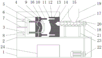
FIG. 1 is a schematic structural view of the present invention;
fig. 2 is a schematic structural diagram of the mold of the present invention when closed.
In the figure: the device comprises a box body 1, a transverse plate 2, a male die 3, a thimble 4, a spring 5, a baffle 6, a fixed column 7, an air cylinder 8, a cooling pipeline 9, a registration column 10, a female die 11, a registration groove 12, an injection port 13, a buffer section 14, an injection cavity 15, an injection molding piece 16, a heating cavity 17, a turbine rod 18, a feeding port 19, a belt pulley 20, a belt 21, a motor 22, a support frame 23 and a finished product collecting box 24.
Detailed Description
The technical solutions in the embodiments of the present invention will be described clearly and completely with reference to the accompanying drawings in the embodiments of the present invention, and it is obvious that the described embodiments are only some embodiments of the present invention, not all embodiments. Based on the embodiments in the present invention, all other embodiments obtained by a person skilled in the art without creative work belong to the protection scope of the present invention.
The embodiment of the utility model provides an injection mold for producing and processing automobile parts, as shown in figure 1-2, comprising a box body 1, a transverse plate 2 is fixedly arranged at the top end of the box body 1, a convex mold 3 is movably connected at the top end of the transverse plate 2, a chute is arranged at the upper part of the left end of the transverse plate 2, the bottom of the convex mold 3 is movably connected in the chute, a thimble 4 is movably connected inside the convex mold 3, a spring 5 is movably connected at the left end of the thimble 4, a baffle 6 is fixedly arranged at the left side of the spring 5, the combination quantity of the thimble 4 and the spring 5 is two groups, the thimbles 4 are respectively arranged at the upper end and the lower end of an injection molding piece 16, one side of the spring 5 is fixed on the baffle 6, the other side is fixed on the inner wall of the convex mold 3, a fixed column 7 is fixedly arranged on the, the left side of the male die 3 is fixedly provided with two cylinders 8, one end of each cylinder 8 is fixedly arranged on the inner wall of the box body 1, the other end of each cylinder 8 is fixedly arranged at the upper end and the lower end of the left side of the male die 3 respectively, the cooling pipeline 9 is arranged inside the male die 3, the cooling pipeline 9 is close to the right end of the male die 3, the cooling pipeline 9 is a bending and folding circulating mechanism, the cooling pipeline 9 is arranged inside the male die 3, cooling forming of the injection molding part 16 is accelerated, solution in the female die 11 on the right side cannot be solidified in advance, and working efficiency is improved. The right side of the male die 3 is fixedly provided with a positioning column 10, the top end of the box body 1 is fixedly provided with a female die 11, the left side of the female die 11 is provided with a positioning groove 12, the positioning columns 10 and the positioning grooves 12 are combined into four groups and respectively positioned at four corners of the male die 3 and the female die 11, the superposed position of the positioning columns 10 and the positioning grooves 12 is in a round table shape, an injection port 13 is formed in the female die 11, the right side of the injection port 13 is provided with a buffer section 14, the right side of the buffer section 14 is fixedly connected with an injection cavity 15, the injection port 13 is communicated with the buffer section 14, the diameter of a pipeline of the pipeline is small, the other end of the pipeline is communicated with the tip of the injection cavity 15, and through the design of the buffer section 14, the phenomena that the male die 3. Injection chamber 15's outside fixed mounting has heating chamber 17, injection chamber 15's inside swing joint has turbine rod 18, injection molding 16 is the car handle, be located between terrace die 3 and the die 11 after the cooling is accomplished, turbine rod 18 passes through bearing swing joint with heating chamber 17, heating chamber 17's top fixed mounting has pan feeding mouth 19, pan feeding mouth 19 runs through heating chamber 17 and injection chamber 15, the bottom opening of pan feeding mouth 19 is located the top of turbine rod 18, fixed mounting has belt pulley 20 on the turbine rod 18, belt pulley 20 has motor 22 through belt 21 swing joint, motor 22 is three-phase asynchronous machine, can realize turbine rod 18's positive and negative rotation fast through three-phase asynchronous machine 22, make injection chamber 15 interior solution melt more even. The turbine rod 18 is positioned in the center of the injection cavity 15, the heating cavity 17 is wrapped on the injection cavity 15, the bottom of the heating cavity 17 is fixedly provided with a support frame 23, and the bottom of the male die 3 is provided with a finished product collecting box 24.
The electrical components presented in the document are all electrically connected with an external master controller and 220V mains, and the master controller can be a conventional known device controlled by a computer or the like.
The working principle is as follows: when the device is used, solid plastic particles are poured from the feeding port 19 and enter the injection cavity 15, the particles are melted under the action of the heating cavity 17, and the motor 22 drives the turbine rod 18 to rotate so as to stir the particles in the melting process. During injection molding, the cylinder 8 pushes the male die 3 to move forwards, the fixing column 7 is separated from the baffle 6, the restoring force of the spring 5 pushes the baffle 6 to the inner wall of the left side of the male die 3, the ejector pin 4 is matched with the wall of the cavity, the male die 3 is attached to the female die 11 through the matching of the positioning column 10 and the positioning groove 12, and at the moment, the melted solution is injected into the cavity through the buffer section 14 and the injection port 13 under the action of the turbine rod 18. After cooling, the air cylinder 8 pulls the male die 3 back, the baffle 6 is limited by the fixing column 7, the ejector pin 4 is moved out of the die cavity, demoulding is completed, finished products fall into the finished product collecting box 24, a small amount of cooling plastic of the injection port 13 can be attached to the finished products, the solution can be remained in the buffer section 14, the solution is prevented from overflowing, and in the intermittent working process, the motor 22 can rotate reversely, so that the solution can not be solidified and can be uniformly melted.
It is noted that, herein, relational terms such as first and second, and the like may be used solely to distinguish one entity or action from another entity or action without necessarily requiring or implying any actual such relationship or order between such entities or actions. Also, the terms "comprises," "comprising," or any other variation thereof, are intended to cover a non-exclusive inclusion, such that a process, method, article, or apparatus that comprises a list of elements does not include only those elements but may include other elements not expressly listed or inherent to such process, method, article, or apparatus.
Although embodiments of the present invention have been shown and described, it will be appreciated by those skilled in the art that changes, modifications, substitutions and alterations can be made in these embodiments without departing from the principles and spirit of the invention, the scope of which is defined in the appended claims and their equivalents.
Claims (10)
1. The utility model provides an injection mold is used in automobile parts production and processing, includes box (1), its characterized in that: the top end of the box body (1) is fixedly provided with a transverse plate (2), the top end of the transverse plate (2) is movably connected with a male die (3), the inner part of the male die (3) is movably connected with a thimble (4), the left end of the thimble (4) is movably connected with a spring (5), the left side of the spring (5) is fixedly provided with a baffle (6), the box body (1) is fixedly provided with a fixed column (7), the left side of the male die (3) is fixedly provided with a cylinder (8), the inner part of the male die (3) is provided with a cooling pipeline (9), the right side of the male die (3) is fixedly provided with an alignment column (10), the top end of the box body (1) is fixedly provided with a female die (11), the left side of the female die (11) is provided with an alignment groove (12), the inner part of the female die (11) is provided with an injection port, the right side fixedly connected with injection chamber (15) of buffer segment (14), the outside fixed mounting of injection chamber (15) has heating chamber (17), the inside swing joint of injection chamber (15) has turbine rod (18), the top fixed mounting of heating chamber (17) has pan feeding mouth (19), fixed mounting has belt pulley (20) on turbine rod (18), belt pulley (20) have motor (22) through belt (21) swing joint, the bottom fixed mounting of heating chamber (17) has support frame (23), the bottom of terrace die (3) is provided with finished product collecting box (24), motor (22) are three-phase asynchronous motor, turbine rod (18) are located the central authorities of injection chamber (15), heating chamber (17) parcel is on injection chamber (15).
2. The injection mold for producing and processing the automobile parts as claimed in claim 1, wherein: the upper part of the left end of the transverse plate (2) is provided with a sliding groove, and the bottom of the male die (3) is movably connected in the sliding groove.
3. The injection mold for producing and processing the automobile parts as claimed in claim 1, wherein: the combined number of the thimbles (4) and the springs (5) is two, the thimbles (4) are respectively positioned at the upper end and the lower end of the injection molding piece (16), one side of each spring (5) is fixed on the baffle (6), and the other side of each spring is fixed on the inner wall of the male die (3).
4. The injection mold for producing and processing the automobile parts as claimed in claim 1, wherein: one end of the fixing column (7) is fixed on the inner wall of the box body (1), and the left end of the male die (3) is provided with a hole matched with the male die.
5. The injection mold for producing and processing the automobile parts as claimed in claim 1, wherein: the number of the cylinders (8) is two, one end of each cylinder is fixedly installed on the inner wall of the box body (1), and the other end of each cylinder is fixedly installed at the upper end and the lower end of the left side of the male die (3).
6. The injection mold for producing and processing the automobile parts as claimed in claim 1, wherein: the cooling pipeline (9) is close to the right end of the male die (3), and the cooling pipeline (9) is a bending and folding circulating mechanism.
7. The injection mold for producing and processing the automobile parts as claimed in claim 1, wherein: the combination of the alignment columns (10) and the alignment grooves (12) is four groups, the four groups are respectively positioned at four corners of the male die (3) and the female die (11), and the coincidence positions of the alignment columns (10) and the alignment grooves (12) are in a round table shape.
8. The injection mold for producing and processing the automobile parts as claimed in claim 1, wherein: the injection port (13) is communicated with the buffer section (14), the diameter of the pipeline of the injection port is small, and the other end of the injection port is communicated with the tip of the injection cavity (15).
9. The injection mold for producing and processing the automobile parts as claimed in claim 3, wherein: the injection molding (16) is an automobile handle, is positioned between the male die (3) and the female die (11) after cooling is completed, and is movably connected with the heating cavity (17) through a bearing.
10. The injection mold for producing and processing the automobile parts as claimed in claim 1, wherein: the feeding port (19) penetrates through the heating cavity (17) and the injection cavity (15), and the bottom opening of the feeding port (19) is positioned above the turbine rod (18).
Priority Applications (1)
| Application Number | Priority Date | Filing Date | Title |
|---|---|---|---|
| CN201921383351.XU CN210733079U (en) | 2019-08-24 | 2019-08-24 | Injection mold is used in automobile parts production and processing |
Applications Claiming Priority (1)
| Application Number | Priority Date | Filing Date | Title |
|---|---|---|---|
| CN201921383351.XU CN210733079U (en) | 2019-08-24 | 2019-08-24 | Injection mold is used in automobile parts production and processing |
Publications (1)
| Publication Number | Publication Date |
|---|---|
| CN210733079U true CN210733079U (en) | 2020-06-12 |
Family
ID=70985240
Family Applications (1)
| Application Number | Title | Priority Date | Filing Date |
|---|---|---|---|
| CN201921383351.XU Expired - Fee Related CN210733079U (en) | 2019-08-24 | 2019-08-24 | Injection mold is used in automobile parts production and processing |
Country Status (1)
| Country | Link |
|---|---|
| CN (1) | CN210733079U (en) |
Cited By (3)
| Publication number | Priority date | Publication date | Assignee | Title |
|---|---|---|---|---|
| CN112454836A (en) * | 2020-12-04 | 2021-03-09 | 杜发德 | Quick demoulding structure for injection molding machine |
| CN113172841A (en) * | 2021-04-27 | 2021-07-27 | 青岛方正精密模塑有限公司 | Multi-runner automobile accessory injection mold and machining method thereof |
| CN113954303A (en) * | 2020-07-21 | 2022-01-21 | 精工爱普生株式会社 | Injection molding device |
-
2019
- 2019-08-24 CN CN201921383351.XU patent/CN210733079U/en not_active Expired - Fee Related
Cited By (6)
| Publication number | Priority date | Publication date | Assignee | Title |
|---|---|---|---|---|
| CN113954303A (en) * | 2020-07-21 | 2022-01-21 | 精工爱普生株式会社 | Injection molding device |
| US11697235B2 (en) | 2020-07-21 | 2023-07-11 | Seiko Epson Corporation | Injection molding apparatus |
| CN113954303B (en) * | 2020-07-21 | 2024-04-19 | 精工爱普生株式会社 | Injection molding device |
| CN112454836A (en) * | 2020-12-04 | 2021-03-09 | 杜发德 | Quick demoulding structure for injection molding machine |
| CN113172841A (en) * | 2021-04-27 | 2021-07-27 | 青岛方正精密模塑有限公司 | Multi-runner automobile accessory injection mold and machining method thereof |
| CN113172841B (en) * | 2021-04-27 | 2022-06-21 | 青岛方正精密模塑有限公司 | Multi-runner automobile accessory injection mold and machining method thereof |
Similar Documents
| Publication | Publication Date | Title |
|---|---|---|
| CN210733079U (en) | Injection mold is used in automobile parts production and processing | |
| CN210390015U (en) | Mould tray with height adjusting function | |
| CN112895286A (en) | Injection molding process production device of automobile part injection mold convenient to use | |
| CN211105275U (en) | Novel automobile injection mold with high demolding speed | |
| CN213947319U (en) | Injection mold is used in production of lithium cell support | |
| CN212579096U (en) | Injection mold convenient to drawing of patterns | |
| CN214000354U (en) | Modular many mouths of moulding plastics flowerpot production mould | |
| CN211616431U (en) | Injection molding processing mold with slide assembly | |
| CN211074515U (en) | Plastic bottle cap mold stripping structure | |
| CN111361085A (en) | Double-layer die machining equipment | |
| CN203844135U (en) | Forming mold for filtering ball of dust collector | |
| CN217968167U (en) | Injection mold for automobile rear lamp shade | |
| CN218256456U (en) | Pipe orifice clamping groove forming mechanism of plastic pipe mold | |
| CN220923211U (en) | A mould for processing round below paint kettle | |
| CN213890860U (en) | Forming tool for eliminating closed angle of molded part | |
| CN216658796U (en) | Automatic demoulding device of plastic forming mould | |
| CN211807455U (en) | Injection mold with accurate positioning | |
| CN214111331U (en) | A quick demolding mould for production of car dust cover | |
| CN219820500U (en) | Injection molding mold for large-sized automobile back door decorative plate | |
| CN220784742U (en) | Mobile phone shell mold capable of automatically demolding | |
| CN212579089U (en) | Processing die for plastic molding | |
| CN218593573U (en) | Upper and lower cover die of control box | |
| CN210336719U (en) | Injection molding device for automobile engine parts | |
| CN211054250U (en) | Injection molding mold and molding machine tool | |
| CN208497550U (en) | A kind of injection molded junction box mold convenient for the material returned |
Legal Events
| Date | Code | Title | Description |
|---|---|---|---|
| GR01 | Patent grant | ||
| GR01 | Patent grant | ||
| CF01 | Termination of patent right due to non-payment of annual fee |
Granted publication date: 20200612 Termination date: 20210824 |
|
| CF01 | Termination of patent right due to non-payment of annual fee |