CN210731130U - Numerical control plane double-end milling machine - Google Patents
Numerical control plane double-end milling machine Download PDFInfo
- Publication number
- CN210731130U CN210731130U CN201921686832.8U CN201921686832U CN210731130U CN 210731130 U CN210731130 U CN 210731130U CN 201921686832 U CN201921686832 U CN 201921686832U CN 210731130 U CN210731130 U CN 210731130U
- Authority
- CN
- China
- Prior art keywords
- dust
- walking frame
- fixed mounting
- screw rod
- milling machine
- Prior art date
- Legal status (The legal status is an assumption and is not a legal conclusion. Google has not performed a legal analysis and makes no representation as to the accuracy of the status listed.)
- Active
Links
Images


Abstract
The utility model discloses a numerical control plane double-end milling machine, including workstation, dust removal mechanism and walking frame, guide rail groove has been seted up to the centre at workstation top, and the inside in guide rail groove is rotated and is installed the one-level screw rod, and the one-level swivel nut is installed to the screw thread on the one-level screw rod, and the one end of one-level screw rod is passed the workstation and is gone up one-level motor output end fixed mounting through shaft coupling and workstation one side, and the top fixed mounting of one-level swivel nut has the walking frame, fixed mounting has dust removal mechanism on one side of walking frame, and equal fixed mounting has the crossbeam on the relative both sides in walking frame upper end, and two crossbeams have the curb plate from the equal fixed mounting in one side of walking frame, the beneficial effect: all install the milling cutter dish on walking frame both sides, realize plane double-end milling cutter processing, reduce the energy consumption and the cost that double-end milling cutter processed when raising the efficiency, dust removal mechanism improves numerically controlled fraise machine's feature of environmental protection, and same power realizes that double-end fraise machine's dust removal is handled, and the practicality is stronger.
Description
Technical Field
The utility model relates to a milling machine especially relates to a numerical control plane double-end milling machine, belongs to milling machine technical field.
Background
The milling machine is a machine tool for milling a workpiece by using a milling cutter, generally, the milling cutter mainly moves by rotating, the workpiece and the milling cutter move by feeding, the milling machine can mill planes, grooves, gear teeth, threads and spline shafts, and can also process more complex molded surfaces, the efficiency is higher than that of a planing machine, and the milling machine is widely applied to mechanical manufacturing and repairing departments.
At present, when the milling machine adopts a single milling cutter to process, the milling cutter needs to be moved when each workpiece is processed, so that the energy consumption and the cost of the processing of the numerical control milling machine are high, the dust generated by the processing of the milling machine can cause environmental pollution, dust removal equipment needs to be arranged on each milling machine, the working time of the dust removal equipment is long when the processing of the single milling cutter is long, the energy consumption and the cost are further increased, and the practicability is poor.
SUMMERY OF THE UTILITY MODEL
The utility model aims at solving present milling machine that exists among the prior art and adopting single milling cutter to add man-hour, need add man-hour at every work piece to milling cutter's removal and go on, thereby the energy consumption that leads to numerical control milling machine to process, the cost is great, and the dust that milling machine processing produced can cause environmental pollution, need be equipped with dust collecting equipment to every milling machine, and single milling cutter processing leads to dust collecting equipment operating time longer when long consuming time, further increase the shortcoming of energy consumption and cost, and the numerical control plane double-end milling machine who provides.
In order to achieve the above purpose, the utility model adopts the following technical scheme:
a numerical control plane double-end milling machine is designed, and comprises a workbench, a dust removing mechanism and a traveling frame, wherein a guide rail groove is formed in the middle of the top of the workbench, a first-stage screw rod is installed in the guide rail groove in a rotating mode, a first-stage screw sleeve is installed on the first-stage screw rod in a threaded mode, one end of the first-stage screw rod penetrates through the workbench and is fixedly installed with a first-stage motor output end on one side of the workbench through a coupler, the traveling frame is fixedly installed at the top of the first-stage screw sleeve, a dust removing mechanism is fixedly installed on one side of the traveling frame, cross beams are fixedly installed on two opposite sides of the upper end of the traveling frame respectively, side plates are fixedly installed on one sides of the cross beams far away from the traveling frame respectively, second-stage screw rods are installed between the two side plates and the traveling frame in a rotating mode, second-stage screw sleeves are installed on the two second-, two the equal fixed mounting in bottom of second grade swivel nut has the install bin, fixed mounting has the pneumatic cylinder in the install bin, the output of pneumatic cylinder has the milling motor through hydraulic stem fixed mounting, the output fixed mounting who mills the motor has the pivot, install bin and milling cutter dish fixed mounting are passed to the one end of pivot.
Preferably, the dust removal mechanism comprises a right dust hood, a left dust hood and a dust collection fan, the right dust hood is fixedly mounted on one side of the walking frame, the left dust hood is fixedly mounted on the walking frame on the side opposite to the right dust hood, the right dust hood and the left dust hood are both connected with the input end of the dust collection fan on one side of the walking frame through dust collection pipes, and the output end of the dust collection fan is connected with the dust collection cloth bag through an air pipe.
Preferably, the dust collectors at the bottoms of the right dust hood and the left dust hood are inclined towards one side of the workbench.
Preferably, the dust removal cloth bag is fixedly installed on the walking frame below the dust collection fan, a dust exhaust port is formed in the bottom of the dust removal cloth bag, and one side, close to the dust exhaust port, of the dust removal cloth bag is bound through an elastic belt.
Preferably, the bottom of the cross beam is provided with a limiting groove, the tops of the two secondary screw sleeves are fixedly provided with sliding blocks, and the sliding blocks are slidably arranged in the limiting groove.
Preferably, the walking frame and the cross beam are arranged in an L-shaped structure.
The utility model provides a pair of numerical control plane double-end milling machine, beneficial effect lies in:
1. the numerical control plane double-end milling machine is simple in structure and convenient to use, the guide rail groove and the mounted walking frame are formed in the middle of the top of the workbench, and the milling cutter discs are mounted on two opposite sides of the upper end of the walking frame through the cross beam, so that the processing of the plane double-end milling cutter on the workbench is realized, the processing efficiency of the numerical control milling machine is effectively improved, the double-end milling cutter is driven by the same walking frame, the efficiency is improved, and meanwhile, the energy consumption and the cost of the double-end milling cutter are reduced;
2. this numerical control plane double-end milling machine through installing the dust removal mechanism on the walking frame, install right suction hood and left suction hood on the relative both sides of walking frame respectively, to milling the dust absorption processing that produces under the effect of dust absorption fan, improve numerical control milling machine's feature of environmental protection, and right suction hood and left suction hood pass through the dust absorption pipe and are connected with same dust absorption fan, and double-end milling machine's dust removal processing is realized to same power, further reduces numerical control double-end milling machine's energy consumption and cost, and the practicality is stronger.
Drawings
Fig. 1 is a schematic structural view of a numerical control plane double-ended milling machine provided by the present invention;
FIG. 2 is a schematic structural view of a dust removing mechanism of the numerical control plane double-ended milling machine of the present invention;
fig. 3 is the utility model provides a numerical control plane double-end milling machine's a department structure schematic diagram.
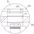
In the figure: 1. a work table; 2. a dust removal mechanism; 21. a right suction hood; 22. a left suction hood; 23. a dust collection fan; 24. a dust collection pipe; 25. a dust removal cloth bag; 3. a guide rail groove; 4. a first-stage screw; 5. a primary thread insert; 6. a first-stage motor; 7. a walking frame; 8. a cross beam; 9. a side plate; 10. a secondary screw; 11. a secondary screw sleeve; 12. a secondary motor; 13. installing a box; 14. a hydraulic cylinder; 15. milling a motor; 16. a rotating shaft; 17. a milling cutter disc; 18. a limiting groove; 19. a slide block.
Detailed Description
The technical solutions in the embodiments of the present invention will be described clearly and completely with reference to the accompanying drawings in the embodiments of the present invention, and it is obvious that the described embodiments are only some embodiments of the present invention, not all embodiments.
Referring to fig. 1-3, a numerical control plane double-end milling machine, includes workstation 1, dust removal mechanism 2 and walking frame 7, guide rail groove 3 has been seted up to the centre at workstation 1 top, the inside of guide rail groove 3 is rotated and is installed one-level screw rod 4, one-level swivel nut 5 is installed to the screw thread on one-level screw rod 4, one end of one-level screw rod 4 passes workstation 1 and through shaft coupling and workstation 1 one side on one-level motor 6 output end fixed mounting, the top fixed mounting of one-level swivel nut 5 has walking frame 7, fixed mounting has dust removal mechanism 2 on one side of walking frame 7, equal fixed mounting has crossbeam 8 on the relative both sides in walking frame 7 upper end, two equal fixed mounting of one side that walking frame 7 was kept away from to crossbeam 8 has curb plate 9, two all rotate between curb plate 9 and the walking frame 7 and install second grade screw rod 10, two equal threaded mounting has second grade swivel nut 11 on the second grade screw rod 10, two the one end of second grade screw rod 10 is all through 12 output end fixed mounting of second grade motor on shaft coupling and curb plate 9, two the equal fixed mounting in bottom of second grade swivel nut 11 has install bin 13, fixed mounting has pneumatic cylinder 14 in the install bin 13, the output of pneumatic cylinder 14 has milling motor 15 through hydraulic stem fixed mounting, milling motor 15's output fixed mounting has pivot 16, install bin 13 and facing cutter 17 fixed mounting are passed to the one end of pivot 16.
The dust removing mechanism 2 comprises a right dust hood 21, a left dust hood 22 and a dust collecting fan 23, wherein one side of the walking frame 7 is fixedly provided with the right dust hood 21, the walking frame 7 on the opposite side of the right dust hood 21 is fixedly provided with the left dust hood 22, the right dust hood 21 and the left dust hood 22 are both connected with the input end of the dust collecting fan 23 on one side of the walking frame 7 through a dust collecting pipe 24, the output end of the dust collecting fan 23 is connected with a dust collecting cloth bag 25 through an air pipe, the right dust hood 21 and the left dust hood 22 realize double-end milling cutter dust collecting treatment of the milling machine under the same power dust collecting fan 23, the energy consumption is low, the cost is low, the dust collecting machines at the bottoms of the right dust hood 21 and the left dust hood 22 are both obliquely arranged towards one side of the workbench 1, so that a dust collecting port of the dust hood collects dust towards the workbench 1, the effect is better, the dust collecting cloth bag 25 is fixedly arranged on the walking frame 7 below the dust collecting fan 23, the dust exhaust port has been seted up to the bottom of dust removal sack 25, one side that dust removal sack 25 is close to the dust exhaust port is tied up through the elastic webbing, conveniently handles long-pending dust of staying in dust removal sack 25, spacing groove 18 has been seted up to the bottom of crossbeam 8, two the equal fixed mounting in top of second grade swivel nut 11 has slider 19, slider 19 slidable mounting is in spacing groove 18, and slider 19 prevents that second grade swivel nut 11 from rotating in the spacing slip of spacing groove 18, be the setting of L type structure between walking frame 7 and the crossbeam 8, guarantee that milling cutter dish 17 horizontal migration mills.
The working principle is as follows: when the device is used, a workpiece is arranged on the workbench 1 on two opposite sides of the walking frame 7, the hydraulic cylinder 14 in the installation box 13 pushes the milling motor 15 and the milling cutter head 17 to move downwards through the hydraulic rod, so that the milling cutter head 17 is contacted with the surface of the workpiece, the milling motor 15 rotates to drive the rotating shaft 16 and the milling cutter head 17 to rotate for milling, the primary motor 6, the secondary motor 12 and the dust suction fan 23 are started simultaneously, the primary motor 6 rotates to drive the primary screw rod 4 in the guide rail groove 3 to rotate, the primary screw sleeve 5 moves on the primary screw rod 4 to drive the walking frame 7 to move on the workbench 1, the secondary motor 12 rotates to drive the secondary screw rod 10 to rotate, the secondary screw sleeve 11 moves on the secondary screw rod 10 to drive the installation box 13 and the milling cutter head 17 to move, meanwhile, the sliding block 19 on the secondary screw sleeve 11 slides in the limiting groove 18 on the cross beam 8 in a limiting way, and under the action of the dust, The left dust hood 22 enters the dust collection pipe 24 and then enters the dust collection cloth bag 25 through the dust collection pipe 24, dust generated by milling is collected in the dust collection cloth bag 25, the facing cutter 17 is installed on two opposite sides of the upper end of the walking frame 7 through the cross beam 8, machining of a plane double-end milling cutter on the workbench 1 is achieved, machining efficiency of the numerically controlled milling machine is effectively improved, the double-end milling cutter is driven to move by the same walking frame 7, efficiency is improved, energy consumption and cost of machining of the double-end milling cutter are reduced, dust generated by milling is absorbed and treated by the dust collection mechanism 2, environmental friendliness of the numerically controlled milling machine is improved, the right dust hood 21 and the left dust hood 22 are connected with the same dust collection fan 23 through the dust collection pipe 24, dust removal treatment of the double-end milling machine is achieved through the same power, and energy consumption and cost of the numerically controlled.
The above, only be the concrete implementation of the preferred embodiment of the present invention, but the protection scope of the present invention is not limited thereto, and any person skilled in the art is in the technical scope of the present invention, according to the technical solution of the present invention and the utility model, the concept of which is equivalent to replace or change, should be covered within the protection scope of the present invention.
Claims (6)
1. The numerical control plane double-end milling machine is characterized by comprising a workbench (1), a dust removing mechanism (2) and a walking frame (7), wherein a guide rail groove (3) is formed in the middle of the top of the workbench (1), a first-stage screw rod (4) is installed in the guide rail groove (3) in a rotating mode, a first-stage screw sleeve (5) is installed on the first-stage screw rod (4) in a threaded mode, one end of the first-stage screw rod (4) penetrates through the workbench (1) and is fixedly installed with an output end of a first-stage motor (6) on one side of the workbench (1) through a coupler, the walking frame (7) is fixedly installed at the top of the first-stage screw sleeve (5), the dust removing mechanism (2) is fixedly installed on one side of the walking frame (7), cross beams (8) are fixedly installed on two opposite sides of the upper end of the walking frame (7), and side plates (9) are fixedly installed on one sides, far away from, two equal rotation between curb plate (9) and the walking frame (7) is installed second grade screw rod (10), two equal threaded mounting has second grade swivel nut (11), two on second grade screw rod (10) second grade motor (12) output end fixed mounting, two on shaft coupling and curb plate (9) are all passed through to the one end of second grade screw rod (10) the equal fixed mounting in bottom of second grade swivel nut (11) has install bin (13), fixed mounting has pneumatic cylinder (14) in install bin (13), the output of pneumatic cylinder (14) has milling motor (15) through hydraulic stem fixed mounting, the output fixed mounting who mills motor (15) has pivot (16), the one end of pivot (16) is passed install bin (13) and milling cutter dish (17) fixed mounting.
2. The numerical control plane double-end milling machine according to claim 1, wherein the dust removing mechanism (2) comprises a right dust hood (21), a left dust hood (22) and a dust suction fan (23), a right dust hood (21) is fixedly installed on one side of the walking frame (7), a left dust hood (22) is fixedly installed on the walking frame (7) on the opposite side of the right dust hood (21), the right dust hood (21) and the left dust hood (22) are both connected with the input end of the dust suction fan (23) on one side of the walking frame (7) through a dust suction pipe (24), and the output end of the dust suction fan (23) is connected with the dust removal cloth bag (25) through an air pipe.
3. A numerically controlled planar double-ended milling machine according to claim 2, wherein the suction cleaners at the bottom of the right suction hood (21) and the left suction hood (22) are both inclined toward one side of the table (1).
4. The numerical control plane double-ended milling machine according to claim 2, wherein the dust removal cloth bag (25) is fixedly installed on the traveling frame (7) below the dust suction fan (23), a dust discharge port is formed in the bottom of the dust removal cloth bag (25), and one side of the dust removal cloth bag (25) close to the dust discharge port is bundled by an elastic belt.
5. The numerical control plane double-ended milling machine according to claim 1, wherein a limiting groove (18) is formed in the bottom of the cross beam (8), sliding blocks (19) are fixedly mounted on the tops of the two secondary screw sleeves (11), and the sliding blocks (19) are slidably mounted in the limiting groove (18).
6. A machine according to claim 1, characterized in that said travelling carriage (7) and said cross-member (8) are arranged in an L-shaped configuration.
Priority Applications (1)
| Application Number | Priority Date | Filing Date | Title |
|---|---|---|---|
| CN201921686832.8U CN210731130U (en) | 2019-10-10 | 2019-10-10 | Numerical control plane double-end milling machine |
Applications Claiming Priority (1)
| Application Number | Priority Date | Filing Date | Title |
|---|---|---|---|
| CN201921686832.8U CN210731130U (en) | 2019-10-10 | 2019-10-10 | Numerical control plane double-end milling machine |
Publications (1)
| Publication Number | Publication Date |
|---|---|
| CN210731130U true CN210731130U (en) | 2020-06-12 |
Family
ID=70984071
Family Applications (1)
| Application Number | Title | Priority Date | Filing Date |
|---|---|---|---|
| CN201921686832.8U Active CN210731130U (en) | 2019-10-10 | 2019-10-10 | Numerical control plane double-end milling machine |
Country Status (1)
| Country | Link |
|---|---|
| CN (1) | CN210731130U (en) |
Cited By (1)
| Publication number | Priority date | Publication date | Assignee | Title |
|---|---|---|---|---|
| CN117086386A (en) * | 2023-10-07 | 2023-11-21 | 安徽朗越能源股份有限公司 | Lithium battery pack processing equipment capable of preventing lithium ion battery electrolyte from leaking |
-
2019
- 2019-10-10 CN CN201921686832.8U patent/CN210731130U/en active Active
Cited By (1)
| Publication number | Priority date | Publication date | Assignee | Title |
|---|---|---|---|---|
| CN117086386A (en) * | 2023-10-07 | 2023-11-21 | 安徽朗越能源股份有限公司 | Lithium battery pack processing equipment capable of preventing lithium ion battery electrolyte from leaking |
Similar Documents
| Publication | Publication Date | Title |
|---|---|---|
| CN213592453U (en) | Steel edge burr removing device | |
| CN215659399U (en) | Metal workpiece machining platform | |
| CN210731130U (en) | Numerical control plane double-end milling machine | |
| CN105150055A (en) | Robot abrasive belt grinding machine for large flat-plate type workpiece | |
| CN210388667U (en) | Grinding device convenient to adjust for machining | |
| CN203124723U (en) | Milling machine capable of removing casting heads of castings | |
| CN212351385U (en) | Grinding device is used in timber processing | |
| CN212527136U (en) | Grinding device for metal part machining | |
| CN214815105U (en) | Drilling processing equipment for aluminum alloy template | |
| CN216264919U (en) | Be applied to milling machine of milling process | |
| CN213889379U (en) | Groove machining device for steel plate | |
| CN214922677U (en) | Waste collecting device for fixed beam planer type milling machine | |
| CN216299564U (en) | Engraver with from clearance function | |
| CN210818385U (en) | Engraving and milling device for faucet production | |
| CN213197927U (en) | Cutting device for wooden packaging box | |
| CN206501198U (en) | A kind of multi-functional processing plane lathe of large-scale timber | |
| CN205520468U (en) | Novel vertical machine tool of high -grade numerical control | |
| CN219005558U (en) | Quartz special-shaped piece machining device | |
| CN219336108U (en) | Automatic edge milling machine for plate processing | |
| CN212635359U (en) | Burnishing device is used in processing of alloy saw bit | |
| CN204450145U (en) | A kind of for processing the half-finished/scouring machine that puts the first edge on a knife or a pair of scissors in advance of alloy | |
| CN219967444U (en) | Grinding machine for steel processing | |
| CN217317001U (en) | Large-scale part longmen processing equipment | |
| CN220862828U (en) | Workbench for guide rail planing machine | |
| CN218362494U (en) | Multifunctional chamfering device for aluminum alloy doors and windows |
Legal Events
| Date | Code | Title | Description |
|---|---|---|---|
| GR01 | Patent grant | ||
| GR01 | Patent grant | ||
| TR01 | Transfer of patent right |
Effective date of registration: 20210721 Address after: 425000 north of Miaotang Road, Zhangjiajie Industrial Park, Dao County, Yongzhou City, Hunan Province Patentee after: Hunan Jiazhao Intelligent Machinery Manufacturing Co.,Ltd. Address before: 523000 Xinhe jute farm, Wanjiang District, Dongguan City, Guangdong Province Patentee before: DONGGUAN YUXIN MACHINERY Co.,Ltd. |
|
| TR01 | Transfer of patent right |