CN210713433U - Hidden frame glass curtain wall system - Google Patents
Hidden frame glass curtain wall system Download PDFInfo
- Publication number
- CN210713433U CN210713433U CN201921621494.XU CN201921621494U CN210713433U CN 210713433 U CN210713433 U CN 210713433U CN 201921621494 U CN201921621494 U CN 201921621494U CN 210713433 U CN210713433 U CN 210713433U
- Authority
- CN
- China
- Prior art keywords
- plate
- frame
- curtain wall
- wall system
- glass curtain
- Prior art date
- Legal status (The legal status is an assumption and is not a legal conclusion. Google has not performed a legal analysis and makes no representation as to the accuracy of the status listed.)
- Active
Links
Images


Abstract
The utility model discloses a hidden frame glass curtain wall system sets up glass panels on adjacent entablature and bottom end rail, and every crossbeam includes framework and two apron of assembly side about the framework, and the front end of framework has last connection core and lower connection core, and the last connection core of bottom end rail inserts glass panels bottom inboard attaches the frame and forms the cooperation down, and the lower connection core of entablature inserts glass panels top inboard and attaches the frame and form the cooperation, fixes glass panels on entablature and entablature. The utility model discloses a direct bayonet connection simplifies mounting structure, improves the installation effectiveness, attaches the frame simultaneously and prevents that glass panels from empting, attaches the frame down and plays bearing and fixed action, improves the reliability of glass panels junction, and is safe firm more.
Description
Technical Field
The utility model belongs to the technical field of building curtain system and specifically relates to a hidden frame glass curtain wall system.
Background
The building curtain wall is a building outer protective structure or decorative structure which is composed of a supporting structure system and a panel, has certain displacement capacity relative to a main structure or can adapt to the displacement of the main structure and does not bear the action of the main structure. With the continuous development of curtain wall technology, glass curtain walls are widely applied to various high-rise buildings nowadays. The building glass curtain wall can be classified into a hidden frame glass curtain wall, a semi-hidden frame glass curtain wall and an exposed frame glass curtain wall according to the appearance. The hidden frame glass curtain wall is a frame supporting glass curtain wall with the periphery of glass bonded to the outer side face of the metal frame through silicone structural sealant. The existing hidden frame glass curtain wall usually adopts structural adhesive to carry out soft connection, and the connection mode is easily influenced by the outside world, so that the connection structure is failed, and potential safety hazards appear. The existing hidden frame glass curtain wall is usually installed by means of pressing plates and bolts, and in order to support the weight of a glass panel, an independent supporting plate is often required to be arranged, so that the defects of complicated working procedures, low working efficiency and the like exist in installation operation.
SUMMERY OF THE UTILITY MODEL
The applicant provides a hidden frame glass curtain wall system with a reasonable structure aiming at the defects of low safety, complex installation operation, low working efficiency and the like of the existing hidden frame glass curtain wall, and the hidden frame glass curtain wall system adopts direct plug-in connection, simplifies the installation structure, improves the installation efficiency, improves the reliability of the joint of the glass panels, and is safer and firmer.
The utility model discloses the technical scheme who adopts as follows:
the utility model provides a hidden frame glass curtain wall system, sets up glass panels on adjacent entablature and bottom end rail, every crossbeam includes framework and two apron of assembly side about the framework, and the front end of framework has last connection core and connects the core down, and the last connection core of bottom end rail inserts glass panels bottom inboard attaches the frame down and forms the cooperation, and the lower connection core of entablature inserts glass panels top inboard and attaches the frame on and form the cooperation, fixes glass panels on bottom end rail and entablature.
As a further improvement of the above technical solution:
the upper connecting core is shaped like ⊥ and comprises a horizontal bottom plate and a vertical plate vertically erected above the bottom plate.
The lower attached frame comprises a supporting plate, a long vertical plate, a flat folded plate and a short vertical plate which are integrally formed, the long vertical plate, the flat folded plate and the short vertical plate enclose a square groove, and the upright plate of the upper connecting core is sleeved with a flexible adhesive tape and then inserted into the square groove of the lower attached frame.
The layer board level sets up, and the rear end of layer board is upwards connected the lower extreme of long riser perpendicularly, and the front end of flat folded plate is connected perpendicularly to the upper end of long riser, and the rear end of flat folded plate is downwards connected the upper end of short riser perpendicularly.
The outer portions of the corners of the supporting plate and the long vertical plate of the lower auxiliary frame are provided with a right-angle bayonet, and the right-angle bayonet abuts against the front end of the bottom plate of the upper connecting core to form a supporting point.
The lower connecting core is L-shaped and comprises a horizontal straight plate and a folded plate vertically connected with one end of the straight plate.
The upper auxiliary frame comprises a long vertical plate, a flat folded plate and a short vertical plate which are integrally formed, the long vertical plate, the flat folded plate and the short vertical plate enclose a square groove, and the folded plate of the lower connecting core is inserted into the square groove of the upper auxiliary frame after being sleeved with a flexible adhesive tape.
The upper end of the long vertical plate is vertically connected with the front end of the flat folded plate, and the rear end of the flat folded plate is vertically connected with the upper end of the short vertical plate downwards.
The frame body of the beam comprises a rear plate, an upper plate, a lower plate, a front plate and an upper connecting core and a lower connecting core which are integrally formed, the rear plate is of an Contraband-shaped structure, the front plate is parallel to the rear plate, and the upper plate and the lower plate are parallel to each other and are vertically positioned between the front plate and the rear plate.
The back plate and the front plate form an upward notch and a downward notch, the cover plate is matched with the corresponding notches, the frame body of the beam is sealed up and down, and a complete beam surface is formed.
The utility model has the advantages as follows:
the utility model discloses set up glass panels on adjacent entablature and bottom end rail, the front end of the framework of crossbeam has last connection core and lower connection core, and the last connection core of bottom end rail inserts the inboard lower frame formation cooperation that attaches in glass panels bottom, and the lower connection core of entablature inserts the inboard frame formation cooperation that attaches in glass panels top, and glass panels adopts the clamp plate fixed on both sides about, fixes glass panels on bottom end rail and entablature. The utility model discloses a direct bayonet connection simplifies mounting structure, improves the installation effectiveness, attaches the frame simultaneously and prevents that glass panels from empting, attaches the frame down and plays bearing and fixed action, improves the reliability of glass panels junction, and is safe firm more.
The utility model discloses a attach the frame down and contain the layer board, need not extra installation layer board, solved the problem of prior art installation layer board alone, save installation procedure, improve work efficiency. The utility model discloses the atress department that attaches the frame under sets up the right angle bayonet socket, and the right angle bayonet socket supports and leans on the front end at the bottom plate of last connection core, forms a strong point, makes glass panels's weight directly transmit the crossbeam through flexible adhesive tape on, increases bearing capacity, has simplified installation procedure, and the relation of connection is firm reliable. The cover plate seals the frame body of the cross beam from top to bottom, the upper connecting core and the lower connecting core on the cross beam, and the lower attached frame and the upper attached frame of the glass panel are sealed inside the cross beam to form a complete cross beam surface, so that the installation is convenient, and the appearance effect of the cross beam is not influenced. The utility model discloses the flexible adhesive tape of suit on the board of sticking up of last connection core and the board of turning up of lower connection core makes an adhesive tape can two-way atress, and the positive negative wind-load that the buffering bore reduces the noise that produces.
Drawings
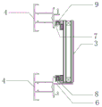
Fig. 1 is a vertical cross-sectional view of the present invention.
Fig. 2 is a simplified vertical cross-sectional view of fig. 1.
Fig. 3 is a cross-sectional view of a beam.
FIG. 4 is a cross-sectional view of a flexible strip of glue.
Fig. 5 is a sectional view of the lower sub-frame.
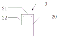
Fig. 6 is a sectional view of the upper attached frame.
In the figure: 1. an upper cross beam; 2. a lower cross beam; 3. a glass panel; 4. a frame body; 5. a cover plate; 6. an upper connecting core; 7. a lower connecting core; 8. a lower auxiliary frame; 9. an upper attached frame; 10. a flexible adhesive tape; 11. a back plate; 12. an upper plate; 13. a lower plate; 14. a front plate; 15. a base plate; 16. erecting a plate; 17. a flat plate; 18. a folding plate; 19. a support plate; 20. a long vertical plate; 21. flatly folding the plate; 22. a short riser; 23. and (4) supporting points.
Detailed Description
The following describes embodiments of the present invention with reference to the drawings.
As shown in fig. 1 and 2, the hidden frame glass curtain wall system of the present invention is formed by connecting a beam and a vertical column vertically to form a frame of a curtain wall, and a glass panel 3 is arranged between the adjacent upper beam 1 and the lower beam 2. Each crossbeam comprises a frame body 4 and two cover plates 5 assembled on the upper side and the lower side of the frame body 4, the front end of the frame body 4 is provided with an upper connecting core 6 and a lower connecting core 7, the upper connecting core 6 of the lower crossbeam 2 is matched with a lower attached frame 8 on the inner side of the bottom of the glass panel 3, the lower connecting core 7 of the upper crossbeam 1 is matched with an upper attached frame 9 on the inner side of the top of the glass panel 3, and the bottom and the top of the glass panel 3 are fixed on the lower crossbeam 2 and the upper crossbeam 1.
As shown in FIG. 3, the frame body 4 of the cross beam comprises a rear plate 11, an upper plate 12, a lower plate 13, a front plate 14 and an upper connecting core 6 and a lower connecting core 7 which are integrally formed, the rear plate 11 is Contraband-shaped and is positioned at the rear part of the cross beam, the front plate 14 and the rear plate 11 are parallel to each other, the front plate 14 is shorter than the rear plate 11, the upper plate 12 and the lower plate 13 are parallel to each other, the upper plate 12 and the lower plate 13 are vertically positioned between the front plate 14 and the rear plate 11, the rear plate 11 and the front plate 14 form an upper notch and a lower notch, the cover plates 5 are matched with the corresponding notches to form the upper surface and the lower surface of the cross beam together, the cover plates 5 are provided with an extending edge on the outer side of the front plate 14 of the frame body 4, the extending edges of the upper cover plate 5 and the lower cover plate 5 enclose the upper connecting core 6 and the lower connecting core 7 and the lower attached frame 8 and the upper attached frame 9 of the adjacent glass panel 3, the upper attached core 6 is ⊥ -shaped, the upper connecting core 6 is ⊥ -shaped and comprises a horizontal bottom plate 15 and a vertical adhesive tape 16, the upper folded plate is a horizontal adhesive tape 17, the upper folded and upper folded core plate is a vertical adhesive tape 17, the upper folded and the upper folded.
As shown in fig. 5, the lower attachment frame 8 includes a pallet 19, long risers 20, flat flaps 21, and short risers 22, which are integrally formed. The layer board 19 level sets up, and the rear end of layer board 19 is the vertical lower extreme of direct connection long riser 20 of top, and the front end of flat folded plate 21 is connected perpendicularly to the upper end of long riser 20, and the rear end of flat folded plate 21 is the vertical upper end of connecting short riser 22 downwards. The long vertical plate 20, the flat folded plate 21 and the short vertical plate 22 of the lower auxiliary frame 8 enclose a square groove with a downward opening. The bottom end of the glass panel 3 is connected with the supporting plate 19 through a gasket, and the inner side of the bottom of the glass panel 3 is attached and connected with the long vertical plate 20 through structural adhesive. When the upper connecting core 6 of the lower beam 2 is matched with the lower attached frame 8 at the inner side of the bottom of the glass panel 3, the upright plate 16 of the upper connecting core 6 is inserted into the square groove of the lower attached frame 8, and the flexible adhesive tape 10 wrapping the upright plate 16 is filled in the square groove. The outer part of the corner of the supporting plate 19 and the long vertical plate 20 of the lower auxiliary frame 8 is provided with a right-angle bayonet which abuts against the front end of the bottom plate 15 of the upper connecting core 6 to form a supporting point 23.
As shown in fig. 6, the upper attachment frame 9 includes a long riser 20, a flat flap 21, and a short riser 22, which are integrally formed. The upper end of the long vertical plate 20 is vertically connected with the front end of the flat folding plate 21, and the rear end of the flat folding plate 21 is vertically connected with the upper end of the short vertical plate 22. The long vertical plate 20, the flat folded plate 21 and the short vertical plate 22 of the upper auxiliary frame 9 enclose a square groove with a downward opening. The top inner side of the glass panel 3 is jointed with the long vertical plate 20 through structural adhesive. When the lower connecting core 7 of the upper beam 1 is matched with the upper auxiliary frame 9 on the inner side of the top of the glass panel 3, the folded plate 18 of the lower connecting core 7 is inserted into the square groove of the upper auxiliary frame 9, and the flexible adhesive tape 10 wrapping the folded plate 18 is filled in the square groove.
Referring to fig. 1 and 2, the implementation of the present invention will now be described by taking two upper and lower beams and a glass panel 3 installed between the two upper and lower beams as an example.
First, the frame bodies 4 of the two cross beams are first attached to the columns, and the front end of the frame body 4 of each cross beam has an upper connecting core 6 and a lower connecting core 7. The flexible rubber strip 10 is sleeved on the upright plate 16 of the upper connecting core 6 of the lower cross beam 2 and the folded plate 18 of the lower connecting core 7 of the upper cross beam 1.
Secondly, the glass panel 3 is prefabricated, the lower auxiliary frame 8 is arranged on the inner side of the bottom of the glass panel 3 in a bonding mode through structural adhesive, and the upper auxiliary frame 9 is arranged on the inner side of the top of the glass panel 3 in a bonding mode. The bottom end of the glass panel 3 is connected with the supporting plate 19 through a gasket, and the inner side of the bottom of the glass panel 3 is attached and connected with the long vertical plate 20 through structural adhesive. The top inner side of the glass panel 3 is jointed with the long vertical plate 20 through structural adhesive.
Third, the glass panel 3 is mounted on the upper and lower beams. On top of the glass panel 3, the folded plate 18 of the lower connecting core 7 of the upper beam 1 is inserted into the square groove of the upper auxiliary frame 9. At the bottom of the glass panel 3, the upright plate 16 of the upper connecting core 6 of the lower beam 2 is inserted into the square groove of the lower attached frame 8, and the right-angle bayonet of the lower attached frame 8 abuts against the front end of the bottom plate 15 of the upper connecting core 6 to form a supporting point 23 for supporting the lower attached frame 8 and the glass panel 3.
Fourthly, cover plates 5 corresponding to the two cross beams are installed, the frame bodies 4 of the two cross beams are sealed to form a complete cross beam surface, and meanwhile, the upper connecting core 6 and the lower connecting core 7 on the cross beams and the lower auxiliary frame 8 and the upper auxiliary frame 9 of the glass panel 3 are sealed inside the cross beams.
Fifthly, the left side and the right side of the glass panel 3 are connected by adopting a pressing plate in a exposed frame type curtain wall connection mode, and then the installation of the curtain wall is completed.
The above description is illustrative of the present invention and is not intended to limit the present invention, and the present invention may be modified in any manner without departing from the spirit of the present invention. For example, the utility model discloses can also use on the stand, set up glass panels 3 between adjacent left stand and right stand. Every stand includes framework 4 and assembles two apron 5 of side about framework 4, and the front end of framework 4 has left connection core and right connection core, and the right connection core of left stand attaches the frame with the left side of glass panels 3 and cooperatees, and the left connection core of right stand attaches the frame with the right side on glass panels 3 right side and cooperatees, fixes the left side and the right side of glass panels 3 on left stand and right stand. The upper and lower sides of the glass panel 3 are connected by a pressing plate in a exposed frame type curtain wall connection mode. The left connecting core is consistent with the lower connecting core 7, and the right connecting core is consistent with the upper connecting core 6. The left auxiliary frame and the right auxiliary frame are both consistent with the upper auxiliary frame 9.
Claims (10)
1. The utility model provides a hidden frame glass curtain wall system which characterized in that: set up glass panels (3) on adjacent entablature (1) and bottom end rail (2), every crossbeam includes framework (4) and assembles two apron (5) of side about framework (4), the front end of framework (4) has upper junction core (6) and lower junction core (7), the lower frame (8) that attaches that insert glass panels (3) bottom inboard of upper junction core (6) of bottom end rail (2) form the cooperation, the lower junction core (7) of entablature (1) insert glass panels (3) top inboard attach frame (9) form the cooperation, fix glass panels (3) on bottom end rail (2) and entablature (1).
2. The hidden framing glass curtain wall system according to claim 1, wherein the upper connecting core (6) is ⊥ -shaped and comprises a horizontal bottom plate (15) and an upright plate (16) vertically erected above the bottom plate (15).
3. The hidden frame glass curtain wall system as claimed in claim 2, wherein: the lower auxiliary frame (8) comprises a supporting plate (19), a long vertical plate (20), a flat folded plate (21) and a short vertical plate (22) which are integrally formed, the long vertical plate (20), the flat folded plate (21) and the short vertical plate (22) enclose a square groove, and the standing plate (16) of the upper connecting core (6) is inserted into the square groove of the lower auxiliary frame (8) after being sleeved with the flexible adhesive tape (10).
4. The hidden frame glass curtain wall system as claimed in claim 3, wherein: the supporting plate (19) is horizontally arranged, the rear end of the supporting plate (19) is upwards and vertically connected with the lower end of the long vertical plate (20), the upper end of the long vertical plate (20) is vertically connected with the front end of the flat folding plate (21), and the rear end of the flat folding plate (21) is downwards and vertically connected with the upper end of the short vertical plate (22).
5. The hidden frame glass curtain wall system as claimed in claim 3, wherein: the outer parts of the corners of the supporting plate (19) of the lower auxiliary frame (8) and the long vertical plate (20) are provided with a right-angle bayonet which abuts against the front end of the bottom plate (15) of the upper connecting core (6) to form a supporting point (23).
6. The hidden frame glass curtain wall system as claimed in claim 1, wherein: the lower connecting core (7) is L-shaped and comprises a horizontal straight plate (17) and a folded plate (18) vertically connected with one end of the straight plate (17).
7. The hidden frame glass curtain wall system as claimed in claim 6, wherein: the upper auxiliary frame (9) comprises a long vertical plate (20), a flat folded plate (21) and a short vertical plate (22) which are integrally formed, the long vertical plate (20), the flat folded plate (21) and the short vertical plate (22) enclose a square groove, and a folded plate (18) of the lower connecting core (7) is inserted into the square groove of the upper auxiliary frame (9) after being sleeved with a flexible adhesive tape (10).
8. The hidden frame glass curtain wall system as claimed in claim 7, wherein: the upper end of the long vertical plate (20) is vertically connected with the front end of the flat folded plate (21), and the rear end of the flat folded plate (21) is downwards vertically connected with the upper end of the short vertical plate (22).
9. The hidden frame glass curtain wall system as claimed in claim 1, wherein: the frame body (4) of the cross beam comprises a rear plate (11), an upper plate (12), a lower plate (13), a front plate (14) and an upper connecting core (6) and a lower connecting core (7) which are integrally formed on the outer side of the front plate (14), the rear plate (11) is of an Contraband-shaped structure, the front plate (14) and the rear plate (11) are parallel to each other, and the upper plate (12) and the lower plate (13) are parallel to each other and are vertically located between the front plate (14) and the rear plate (11).
10. The hidden frame glass curtain wall system as claimed in claim 9, wherein: the rear plate (11) and the front plate (14) form two upward and downward notches, the cover plate (5) is matched with the corresponding notches, the frame body (4) of the beam is sealed up and down, and a complete beam surface is formed.
Priority Applications (1)
| Application Number | Priority Date | Filing Date | Title |
|---|---|---|---|
| CN201921621494.XU CN210713433U (en) | 2019-09-27 | 2019-09-27 | Hidden frame glass curtain wall system |
Applications Claiming Priority (1)
| Application Number | Priority Date | Filing Date | Title |
|---|---|---|---|
| CN201921621494.XU CN210713433U (en) | 2019-09-27 | 2019-09-27 | Hidden frame glass curtain wall system |
Publications (1)
| Publication Number | Publication Date |
|---|---|
| CN210713433U true CN210713433U (en) | 2020-06-09 |
Family
ID=70933821
Family Applications (1)
| Application Number | Title | Priority Date | Filing Date |
|---|---|---|---|
| CN201921621494.XU Active CN210713433U (en) | 2019-09-27 | 2019-09-27 | Hidden frame glass curtain wall system |
Country Status (1)
| Country | Link |
|---|---|
| CN (1) | CN210713433U (en) |
Cited By (1)
| Publication number | Priority date | Publication date | Assignee | Title |
|---|---|---|---|---|
| CN110499855A (en) * | 2019-09-27 | 2019-11-26 | 无锡恒尚装饰工程有限公司 | Concealed frame glass curtain wall system |
-
2019
- 2019-09-27 CN CN201921621494.XU patent/CN210713433U/en active Active
Cited By (1)
| Publication number | Priority date | Publication date | Assignee | Title |
|---|---|---|---|---|
| CN110499855A (en) * | 2019-09-27 | 2019-11-26 | 无锡恒尚装饰工程有限公司 | Concealed frame glass curtain wall system |
Similar Documents
| Publication | Publication Date | Title |
|---|---|---|
| CN210713433U (en) | Hidden frame glass curtain wall system | |
| CN205935344U (en) | Unit formula aluminium veneer curtain wall construction | |
| CN210622053U (en) | Indoor side-mounted curtain wall system | |
| CN212271348U (en) | Roof stepped unit curtain wall system | |
| CN211774927U (en) | Broken line stand unit | |
| CN207700474U (en) | A kind of splicing type waterproof metal decking curtain wall | |
| CN215106817U (en) | Heat preservation and decoration integrated plate with solar power generation function | |
| CN211369194U (en) | Latent frame curtain attaches frame structure | |
| CN214006215U (en) | High-strength anti-seismic aluminum composite plate | |
| CN210562884U (en) | Curtain decorative board fixed connection subassembly | |
| CN206591694U (en) | Aluminum plate unit formula curtain wall | |
| CN218374591U (en) | Inner waterproof glass curtain wall system | |
| CN107035039A (en) | The hidden frame cell cube curtain wall system of super insulation crimping | |
| CN220747356U (en) | Broken line glass curtain wall system | |
| CN211597284U (en) | Aluminum-plastic panel unit curtain wall mounting structure | |
| CN219671795U (en) | Upright post node suitable for arc-shaped closed curtain wall and glass indoor fixation | |
| CN215858468U (en) | Fast-assembling type curtain backplate connection structure and heat preservation curtain system | |
| CN215255561U (en) | Door and window structure with improved sealing effect | |
| CN215759905U (en) | Sunshine room ceiling structure | |
| CN211421529U (en) | Open stone material curtain connection structure | |
| CN213062553U (en) | Interior angle connecting structure of metal plate and glass curtain wall | |
| CN219909533U (en) | BIPV curtain wall with compact structure | |
| CN211341344U (en) | Glass curtain wall mounting structure | |
| CN215888926U (en) | Notch cuttype binding off lines and interior decoration structure | |
| CN216787557U (en) | Full glass and frame support combined glass curtain wall system |
Legal Events
| Date | Code | Title | Description |
|---|---|---|---|
| GR01 | Patent grant | ||
| GR01 | Patent grant | ||
| CP01 | Change in the name or title of a patent holder | ||
| CP01 | Change in the name or title of a patent holder |
Address after: 214117 No.8, Tonghu Road, Ehu Town, Xishan District, Wuxi City, Jiangsu Province Patentee after: Jiangsu Hengshang Energy Saving Technology Co.,Ltd. Address before: 214117 No.8, Tonghu Road, Ehu Town, Xishan District, Wuxi City, Jiangsu Province Patentee before: WUXI HENGSHANG DECORATION ENGINEERING Co.,Ltd. |