CN210713421U - Replaceable unit curtain wall structure - Google Patents
Replaceable unit curtain wall structure Download PDFInfo
- Publication number
- CN210713421U CN210713421U CN201921621803.3U CN201921621803U CN210713421U CN 210713421 U CN210713421 U CN 210713421U CN 201921621803 U CN201921621803 U CN 201921621803U CN 210713421 U CN210713421 U CN 210713421U
- Authority
- CN
- China
- Prior art keywords
- panel
- unit
- frame
- curtain wall
- subframe
- Prior art date
- Legal status (The legal status is an assumption and is not a legal conclusion. Google has not performed a legal analysis and makes no representation as to the accuracy of the status listed.)
- Active
Links
Images




Abstract
The utility model discloses a removable unit curtain wall construction, fixed mounting unit frame on the building major structure, detachable installation panel unit on the unit frame, the panel unit includes the vice frame of panel and installs the glass panels on the vice frame of panel, the vice frame of panel includes the framework and the closed angle portion that extends from the framework, is equipped with the thread groove that corresponds with closed angle portion on the unit frame, and self-tapping nail and thread groove form the cooperation with panel unit and unit frame fastening connection. The utility model discloses detachable installation panel unit on the unit frame, panel unit is made by panel subframe and glass panels in advance, when changing directly dismantle old panel unit, change new panel unit can, reduce the degree of difficulty of changing the installation, it is more convenient to operate, saves the change time, can not reduce the reliability because of changing moreover, reduces to leak and the potential safety hazard.
Description
Technical Field
The utility model belongs to the technical field of building curtain wall facility and specifically relates to a removable unit curtain wall construction.
Background
The building curtain wall is a building outer protective structure or decorative structure which is composed of a supporting structure system and a panel, has certain displacement capacity relative to a main structure or can adapt to the displacement of the main structure and does not bear the action of the main structure. With the continuous development of curtain wall technology, unit glass curtain walls have been widely applied to various high-rise buildings. The existing unit glass curtain wall generally adopts a permanent fixing installation mode, and a glass panel is bonded on a curtain wall unit frame through structural adhesive. During use, the glass panel may be damaged or self-exploded, and the damaged glass panel needs to be replaced. The existing method is that the original unit frame residues are cleaned up, the glue is directly knotted to form the glue to fix the glass panel on the original frame, the indoor and outdoor personnel are needed to operate in a matching manner during replacement, the labor cost is increased, the replacement is time-consuming and labor-consuming, and in addition, due to the limitation of glue hitting in high-altitude operation and on-site, water leakage and potential safety hazards are more after the replacement. The newly-beaten structural adhesive needs a certain curing period, the equipment for fixing the glass panel in the curing period cannot be detached, the time for completing the whole replacement is long, and potential safety hazards also exist.
SUMMERY OF THE UTILITY MODEL
The applicant provides a replaceable unit curtain wall structure with a reasonable structure aiming at the defects that the replacement of the existing unit glass curtain wall is time-consuming and labor-consuming, the potential safety hazard is more after the replacement, the time for the whole replacement is long and the like, the difficulty of replacement and installation can be reduced, the operation is more convenient, the replacement time is saved, the reliability can not be reduced due to the replacement, and the water leakage and the potential safety hazard are reduced.
The utility model discloses the technical scheme who adopts as follows:
the utility model provides a removable unit curtain wall construction, fixed mounting unit frame on building major structure, detachable installation panel unit on the unit frame, the panel unit includes the panel subframe and installs the glass panels on the panel subframe, the panel subframe includes the framework and the closed angle portion that extends from the framework, be equipped with the thread groove that corresponds with closed angle portion on the unit frame, self-tapping nail and thread groove form the cooperation with panel unit and unit frame fastening connection.
As a further improvement of the above technical solution:
the thread groove is arranged on the unit frame in a full length mode, and is obliquely arranged towards the outer side, and the notch is opposite to the sharp corner.
The sharp corner part is provided with a mounting hole for arranging a self-tapping screw.
A compressible rubber strip is arranged at the joint between the unit frame and the panel subframe.
The self-tapping screw penetrates through the sharp corner part and the rubber strip and then is screwed into the thread groove to fixedly connect the panel unit and the unit frame.
The panel subframe comprises horizontal subframe and vertical subframe, and four limit positions of glass panels are fixed at four edges of the panel subframe through structural adhesive.
And the two transverse auxiliary frames are correspondingly provided with transverse protective edges which are positioned at the top and the bottom of the glass panel.
And the outer sides of the two vertical auxiliary frames and the two transverse protective edges are also provided with adhesive tape grooves for installing seam blocking adhesive tapes.
The self-tapping screw is a hexagon socket self-tapping screw.
The unit frame is composed of a horizontal frame and a vertical frame.
The utility model has the advantages as follows:
the utility model discloses detachable installation panel unit on the unit frame, panel unit is made by panel subframe and glass panels in advance, when changing directly dismantle old panel unit, change new panel unit can, reduce the degree of difficulty of changing the installation, it is more convenient to operate, saves the change time, can not reduce the reliability because of changing moreover, reduces to leak and the potential safety hazard. The utility model discloses a unit frame adopts the screw thread groove that the notch is outside, the slope set up, and the closed angle portion and the screw thread groove of the vice frame of panel correspond the setting, only need just can accomplish the installation through the self-tapping screw, do not need additionally to attach unnecessary accessory or process the unit frame temporarily, and required spare part is less, and the cooperation of self-tapping screw and screw thread groove is convenient for operate moreover, and stability is longer, and the slope setting of screw thread groove also makes things convenient for the construction operation, improves work efficiency. The utility model discloses a horizontal safe edge of installation on the vice frame of panel supports glass panels, and is more firm reliable. The utility model discloses a hexagonal self-tapping screw in, for other self-tapping screws, the operation is convenient more.
Drawings
Fig. 1 is a perspective view of the present invention.
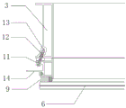
Fig. 2 is a sectional view of section a-a in fig. 1.
Fig. 3 is a sectional view of section B-B in fig. 1.
Fig. 4 is a schematic exploded view of fig. 1.
Fig. 5 is an enlarged view of a portion C in fig. 4.
In the figure: 1. a unit frame; 2. a transverse frame; 3. a mullion; 4. a panel unit; 5. a panel subframe; 6. a glass panel; 7. a transverse subframe; 8. a vertical subframe; 9. structural adhesive; 10. transversely protecting edges; 11. a sharp corner portion; 12. self-tapping screw; 13. a thread groove; 14. seam blocking adhesive tape.
Detailed Description
The following describes embodiments of the present invention with reference to the drawings.
As shown in fig. 1 to 5, the replaceable unit curtain wall structure of the present invention is fixedly installed with a unit frame 1 composed of a horizontal frame 2 and a vertical frame 3 on a building main structure, and a panel unit 4 is detachably installed on the unit frame 1. The panel unit 4 comprises a panel subframe 5 and a glass panel 6 arranged on the panel subframe 5, the panel subframe 5 comprises a transverse subframe 7 and a vertical subframe 8, four edges of the glass panel 6 are fixed on four edges of the panel subframe 5 through structural adhesive 9, two transverse subframes 10 are correspondingly arranged on the two transverse subframes 7, and the two transverse subframes 10 are positioned at the top and the bottom of the glass panel 6 and clamp the glass panel 6 between the two transverse subframes 7. In cross section, the panel subframe 5 includes a frame body and a pointed portion 11 extending from the frame body, and the pointed portion 11 is provided with a mounting hole in which a self-tapping screw 12 is disposed. The unit frame 1 is provided with a thread groove 13 corresponding to the sharp corner 11, the thread groove 13 is arranged on the unit frame 1 in a whole length and is inclined towards the outside, and the notch is opposite to the sharp corner 11. A compressible rubber strip is provided at the junction between the cell border 1 and the panel subframe 5. The hexagon socket head cap tapping screw 12 passes through the sharp corner 11 and the rubber strip and then is screwed into the thread groove 13 to tightly connect the panel unit 4 and the unit frame 1. And a proper gap is reserved between two adjacent panel units 4, so that the operation of installing the hexagon socket self-tapping screw 12 is facilitated. And the outer sides of the two vertical auxiliary frames 8 and the two transverse protective edges 10 are also provided with adhesive tape grooves for installing seam blocking adhesive tapes 14 and blocking gaps between the panel units 4.
The utility model discloses when implementing, with unit frame 1 fixed mounting on building major structure, unit frame 1 comprises horizontal frame 2 and mullion 3. The unit frame 1 is provided with a thread groove 13 inclined outward. The glass panel 6 is arranged on the panel subframe 5 in a processing workshop, four edges of the glass panel 6 are fixed on four edges of the panel subframe 5 through structural adhesive 9, and the two transverse subframes 7 are provided with transverse protective edges 10 to clamp the glass panel 6 in the middle. The hexagon socket head cap tapping screw 12 passes through the sharp corner 11 and the rubber strip and then is screwed into the thread groove 13 to tightly connect the panel unit 4 and the unit frame 1. A proper gap is left between the two panel units 4 and the screw groove 13 is inclined outward, so that the installation of the tapping screw 12 at the gap is not affected. After the installation is finished, seam blocking adhesive tapes 14 are installed on the outer sides of the vertical auxiliary frame 8 and the transverse protective edge 10, so that a curtain wall structure with the appearance being finished is formed. When glass panels 6 appear the damage and need to be changed, take off detachable self-tapping nail 12, lift panel unit 4 off, with new panel unit 4 install again on unit frame 1 can, need not destroy unit frame 1, simple to operate is swift, required cost reduction moreover.
The above description is illustrative of the present invention and is not intended to limit the present invention, and the present invention may be modified in any manner without departing from the spirit of the present invention.
Claims (10)
1. The utility model provides a removable unit curtain wall construction which characterized in that: fixed mounting unit frame (1) on building major structure, detachable installation panel unit (4) on unit frame (1), panel unit (4) are including panel subframe (5) and install glass panels (6) on panel subframe (5), panel subframe (5) are including framework and sharp bight (11) that extend from the framework, be equipped with thread groove (13) that correspond with sharp bight (11) on unit frame (1), self-tapping nail (12) and thread groove (13) form the cooperation with panel unit (4) and unit frame (1) fastening connection.
2. The replaceable unit curtain wall construction of claim 1 wherein: the thread groove (13) is arranged on the unit frame (1) in a whole length and is obliquely arranged towards the outer side, and the notch is opposite to the sharp corner part (11).
3. The replaceable unit curtain wall construction of claim 1 wherein: the sharp corner (11) is provided with a mounting hole for arranging a self-tapping screw (12).
4. The replaceable unit curtain wall construction of claim 1 wherein: a compressible rubber strip is arranged at the joint between the unit frame (1) and the panel subframe (5).
5. The replaceable unit curtain wall construction of claim 4 wherein: the self-tapping screw (12) penetrates through the sharp corner part (11) and the rubber strip and then is screwed into the thread groove (13) to fixedly connect the panel unit (4) and the unit frame (1).
6. The replaceable unit curtain wall construction of claim 1 wherein: the panel subframe (5) is composed of a transverse subframe (7) and a vertical subframe (8), and four edges of the glass panel (6) are fixed on four edges of the panel subframe (5) through structural adhesive (9).
7. The replaceable unit curtain wall construction of claim 6 wherein: the two transverse subframes (7) are also correspondingly provided with transverse protective edges (10), and the two transverse protective edges (10) are positioned at the top and the bottom of the glass panel (6).
8. The replaceable unit curtain wall construction of claim 7 wherein: and the outer sides of the two vertical auxiliary frames (8) and the two transverse protective edges (10) are also provided with adhesive tape grooves for installing seam blocking adhesive tapes (14).
9. The replaceable unit curtain wall construction of claim 1 wherein: the self-tapping screw (12) is a hexagon socket head self-tapping screw.
10. The replaceable unit curtain wall construction of claim 1 wherein: the unit frame (1) is composed of a horizontal frame (2) and a vertical frame (3).
Priority Applications (1)
| Application Number | Priority Date | Filing Date | Title |
|---|---|---|---|
| CN201921621803.3U CN210713421U (en) | 2019-09-27 | 2019-09-27 | Replaceable unit curtain wall structure |
Applications Claiming Priority (1)
| Application Number | Priority Date | Filing Date | Title |
|---|---|---|---|
| CN201921621803.3U CN210713421U (en) | 2019-09-27 | 2019-09-27 | Replaceable unit curtain wall structure |
Publications (1)
| Publication Number | Publication Date |
|---|---|
| CN210713421U true CN210713421U (en) | 2020-06-09 |
Family
ID=70930524
Family Applications (1)
| Application Number | Title | Priority Date | Filing Date |
|---|---|---|---|
| CN201921621803.3U Active CN210713421U (en) | 2019-09-27 | 2019-09-27 | Replaceable unit curtain wall structure |
Country Status (1)
| Country | Link |
|---|---|
| CN (1) | CN210713421U (en) |
-
2019
- 2019-09-27 CN CN201921621803.3U patent/CN210713421U/en active Active
Similar Documents
| Publication | Publication Date | Title |
|---|---|---|
| CN210713421U (en) | Replaceable unit curtain wall structure | |
| CN204531106U (en) | A kind of sitting posture curtain wall system that can independently change | |
| CN207314597U (en) | All steel section bar fastening piece type partition-type structures | |
| CN112064841A (en) | Built-in internal-replaceable unit window system | |
| CN210459667U (en) | Open composite aluminum plate inlays construction system of window | |
| CN114108901A (en) | Vertical glass wing system of frame curtain wall | |
| CN202300025U (en) | Glass ground-bounce door | |
| CN204850171U (en) | Frame -type curtain wall construction | |
| CN209760533U (en) | Frame of exposed frame glass curtain wall and glass curtain wall applying same | |
| CN112160682A (en) | Semi-hidden frame window sash mounting structure of opening | |
| CN207392547U (en) | A kind of dry method quick assembling unit of glass curtain wall or window | |
| CN216195836U (en) | Indoor side quick detachable frame glass curtain wall structure | |
| CN219261465U (en) | Window with hidden frame opening fan | |
| CN217537467U (en) | Improved structure of green energy-saving building curtain wall | |
| CN214833789U (en) | Curtain wall glass mounting structure and curtain wall | |
| CN216865628U (en) | Hidden frame curtain wall and decorative wing connecting piece convenient to install | |
| CN211143317U (en) | Sunshine room | |
| CN114108900B (en) | Corner glass assembling system for frame glass curtain wall | |
| CN203701837U (en) | Wooden window sleeve | |
| CN218374591U (en) | Inner waterproof glass curtain wall system | |
| CN214995021U (en) | Glass curtain wall mounting structure | |
| CN212656646U (en) | Bottom fixing structure of triangular tent | |
| CN209179195U (en) | A kind of medium-sized and macrotype spherical structural glass room | |
| CN216130484U (en) | Facade structure that contains mesh board | |
| CN210659010U (en) | Blade type canopy structure |
Legal Events
| Date | Code | Title | Description |
|---|---|---|---|
| GR01 | Patent grant | ||
| GR01 | Patent grant | ||
| CP01 | Change in the name or title of a patent holder |
Address after: 214117 No.8, Tonghu Road, Ehu Town, Xishan District, Wuxi City, Jiangsu Province Patentee after: Jiangsu Hengshang Energy Saving Technology Co.,Ltd. Address before: 214117 No.8, Tonghu Road, Ehu Town, Xishan District, Wuxi City, Jiangsu Province Patentee before: WUXI HENGSHANG DECORATION ENGINEERING Co.,Ltd. |
|
| CP01 | Change in the name or title of a patent holder |