CN210713261U - Roof connecting piece and modularization roof connection structure - Google Patents
Roof connecting piece and modularization roof connection structure Download PDFInfo
- Publication number
- CN210713261U CN210713261U CN201921162400.7U CN201921162400U CN210713261U CN 210713261 U CN210713261 U CN 210713261U CN 201921162400 U CN201921162400 U CN 201921162400U CN 210713261 U CN210713261 U CN 210713261U
- Authority
- CN
- China
- Prior art keywords
- plate
- roof
- clamping
- connecting piece
- roof connecting
- Prior art date
- Legal status (The legal status is an assumption and is not a legal conclusion. Google has not performed a legal analysis and makes no representation as to the accuracy of the status listed.)
- Active
Links
Images


Classifications
-
- E—FIXED CONSTRUCTIONS
- E04—BUILDING
- E04B—GENERAL BUILDING CONSTRUCTIONS; WALLS, e.g. PARTITIONS; ROOFS; FLOORS; CEILINGS; INSULATION OR OTHER PROTECTION OF BUILDINGS
- E04B1/00—Constructions in general; Structures which are not restricted either to walls, e.g. partitions, or floors or ceilings or roofs
- E04B1/38—Connections for building structures in general
- E04B1/61—Connections for building structures in general of slab-shaped building elements with each other
- E04B1/6108—Connections for building structures in general of slab-shaped building elements with each other the frontal surfaces of the slabs connected together
- E04B1/612—Connections for building structures in general of slab-shaped building elements with each other the frontal surfaces of the slabs connected together by means between frontal surfaces
- E04B1/6145—Connections for building structures in general of slab-shaped building elements with each other the frontal surfaces of the slabs connected together by means between frontal surfaces with recesses in both frontal surfaces co-operating with an additional connecting element
- E04B1/6162—Connections for building structures in general of slab-shaped building elements with each other the frontal surfaces of the slabs connected together by means between frontal surfaces with recesses in both frontal surfaces co-operating with an additional connecting element the connection made by an additional locking key
-
- E—FIXED CONSTRUCTIONS
- E04—BUILDING
- E04B—GENERAL BUILDING CONSTRUCTIONS; WALLS, e.g. PARTITIONS; ROOFS; FLOORS; CEILINGS; INSULATION OR OTHER PROTECTION OF BUILDINGS
- E04B1/00—Constructions in general; Structures which are not restricted either to walls, e.g. partitions, or floors or ceilings or roofs
- E04B1/62—Insulation or other protection; Elements or use of specified material therefor
- E04B1/66—Sealings
- E04B1/68—Sealings of joints, e.g. expansion joints
- E04B1/6801—Fillings therefor
-
- E—FIXED CONSTRUCTIONS
- E04—BUILDING
- E04B—GENERAL BUILDING CONSTRUCTIONS; WALLS, e.g. PARTITIONS; ROOFS; FLOORS; CEILINGS; INSULATION OR OTHER PROTECTION OF BUILDINGS
- E04B1/00—Constructions in general; Structures which are not restricted either to walls, e.g. partitions, or floors or ceilings or roofs
- E04B1/62—Insulation or other protection; Elements or use of specified material therefor
- E04B1/66—Sealings
- E04B1/68—Sealings of joints, e.g. expansion joints
- E04B1/6812—Compressable seals of solid form
-
- E—FIXED CONSTRUCTIONS
- E04—BUILDING
- E04B—GENERAL BUILDING CONSTRUCTIONS; WALLS, e.g. PARTITIONS; ROOFS; FLOORS; CEILINGS; INSULATION OR OTHER PROTECTION OF BUILDINGS
- E04B2/00—Walls, e.g. partitions, for buildings; Wall construction with regard to insulation; Connections specially adapted to walls
-
- E—FIXED CONSTRUCTIONS
- E04—BUILDING
- E04C—STRUCTURAL ELEMENTS; BUILDING MATERIALS
- E04C2/00—Building elements of relatively thin form for the construction of parts of buildings, e.g. sheet materials, slabs, or panels
- E04C2/30—Building elements of relatively thin form for the construction of parts of buildings, e.g. sheet materials, slabs, or panels characterised by the shape or structure
- E04C2/38—Building elements of relatively thin form for the construction of parts of buildings, e.g. sheet materials, slabs, or panels characterised by the shape or structure with attached ribs, flanges, or the like, e.g. framed panels
Abstract
The utility model relates to a roof connection structure and modularization roof connection structure, it includes a plurality of roofs, connect in roof connecting piece and sealing strip between the roof, the roof connecting piece includes: the upper support middle plate and the lower support middle plate form a support general plate; the top plate connecting piece further comprises at least one group of clamping units. The upper support middle plate and the lower support middle plate which are fixedly spliced are utilized, and the two top plates can be conveniently and quickly connected without assistance of auxiliary manpower. The sealing performance and the weather resistance of the whole clean room are ensured by adopting an embedded sealing pressing strip structure, and the connecting mode of the sealing pressing strips is faster and more efficient than the traditional glass cement sealing mode. The electric wire position of walking has been reserved to new furred ceiling section bar, need not to place the wire way separately, prevents the chaotic field operation of indiscriminate stay cord, saves the cost of labor, improves the installation effectiveness.
Description
Technical Field
The utility model belongs to a building material field, in particular to roof connecting piece and modularization roof connection structure.
Background
The clean room is a space with better tightness, which can control the parameters of air cleanliness, temperature, humidity, pressure, noise and the like according to the requirements. The development of clean rooms is closely related to modern industries, advanced technologies, food industries, medical devices and the like. Due to the environmental requirements of precision machinery industry, semiconductor industry, food, medical industry, etc., the development of clean room technology has been promoted, so that the application of clean rooms in precision machinery, semiconductor, aerospace, atomic energy, food, medical industry, etc. is quite common.
The existing clean room top plate usually has large weight and volume, the height is at least more than 3 meters, and installation and transportation can be completed by a large number of personnel, so that the installation labor cost is high, the installation efficiency is low, and the requirement of the actual engineering installation efficiency is difficult to meet. Moreover, the prior art connection structure between the top plates is easy to be separated, and has no mechanism for temporarily fixing before the installation is completed: this is because the top plate construction has only a simple concavo-convex construction without a snap-fit construction, and thus the top plate is easily detached or inclined when being spliced without manual assistance during installation. The roof concatenation back will lean on sealed glass to glue sealedly, because glass glues self characteristic, can produce the phenomenon of moulding, becoming yellow and ageing after using a period, has influenced whole toilet sealing performance and pleasing to the eye, does not reserve the winding displacement groove for the electric wire after the roof concatenation that has now moreover for the later stage installation electric wire is very inconvenient.
Disclosure of Invention
The utility model aims at providing a roof connecting piece that the installation is nimble convenient and can effectively solve the winding displacement problem.
In order to achieve the above purpose, the utility model adopts the technical scheme that: a roof connecting element comprising: the upper support middle plate and the lower support middle plate form a support general plate; the top plate connecting piece further comprises at least one group of clamping units, and each group of clamping units are formed on two surfaces of the supporting general plate respectively and are symmetrical relative to the supporting general plate; every group the joint unit is including forming support total board on the surface and the joint riser that the interval set up and form every the joint of joint riser surface edge is protruding, the joint protruding with support and form the joint space between the total board.
In another preferred mode, the clamping unit further includes first buffer bumps formed on two side edges of the supporting total plate and at least one second buffer bump respectively formed on two surfaces of the supporting total plate and located between the first buffer bumps and the clamping unit.
In another preferred mode, the insertion part comprises a C-shaped groove body which is fixed at the lower end part of the upper support middle plate and has a small belly size, and a clamping plate which is fixed at the upper end part of the lower support middle plate and is matched with the C-shaped groove body, and the clamping plate is inserted into the C-shaped groove body to fixedly connect the upper support middle plate and the lower support middle plate.
In another preferred mode, the edge of the upper end face of the C-shaped groove body is provided with a clamping protrusion, and a clamping space is formed between the clamping protrusion and the supporting general plate.
In another preferred mode, the clamping plate is provided with a reinforcing rib for improving the connection strength.
In another preferred mode, the insertion opening of the clamping plate is formed by penetrating the side surface of the C-shaped groove body.
Another preferred mode, the roof connecting piece is still including locating the upper end of going up the support medium plate is equipped with the groove of walking and the apron that is used for laying the electric wire, it forms the apron mounting groove that extends along walking the groove extending direction in two lateral walls of groove to walk, the lower extreme of apron has the fixture block of walking the groove bottom extension towards, the fixture block lower extreme has the inclined plane arch that is the inclined plane extension, the protruding card of inclined plane is located in the apron mounting groove.
The utility model also provides a modularization roof connection structure, it includes a plurality of roofs, and connect in roof connecting piece between the roof, the roof connecting piece is above-mentioned arbitrary the roof connecting piece.
Another preferred mode, the roof includes the board main part, offers the slot that is the big belly of T font on the side of board main part and mouthful is little, the slot is formed by the first order slot of deeper department and the second grade slot of shallower department, the second grade slot is protruding by two relative second grades and forms, the protruding card of second grade is located respectively and is supported in the joint space of total board with one side.
Another preferred mode, it still includes the installation between two adjacent roof and with roof connecting piece matched with sealing bead, sealing bead includes: sealing strip body, formation are in the first sealed blend stop of sealing strip body limit portion and formation are in the sealed blend stop of the multichannel second on the surface of sealing strip body two, the thickness of sealing strip body is in first sealed blend stop is located one side and is reduced gradually in the direction that corresponds the opposite side, and its material is rigid plastic, first sealed blend stop with the sealed blend stop of second is wedge structure mutually independently, and its material is soft plastic.
Because of the application of the technical scheme, compared with the prior art, the utility model has the following advantages: the utility model discloses the adoption fritter roof of realization roof and roof has alleviateed roof weight and volume easy to assemble and has carried the high installation effectiveness and practiced thrift the human cost. The upper support middle plate and the lower support middle plate which are fixedly spliced are utilized, and the two top plates can be conveniently and quickly connected without assistance of auxiliary manpower. The sealing performance and the weather resistance of the whole clean room are ensured by adopting an embedded sealing pressing strip structure, and the connecting mode of the sealing pressing strips is faster and more efficient than the traditional glass cement sealing mode. The electric wire position of walking has been reserved to new furred ceiling section bar, need not to place the wire way separately, prevents the chaotic field operation of indiscriminate stay cord, saves the cost of labor, improves the installation effectiveness.
Drawings
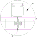
FIG. 1 is a front view of a top plate connector;
FIG. 2 is a front view of the top plate;
FIG. 3 is a front view of the sealing bead;
FIG. 4 is a front view of a modular ceiling tile attachment structure;
FIG. 5 is a perspective view of a modular ceiling tile attachment structure.
Detailed Description
The invention will be further described with reference to examples of embodiments shown in the drawings.
As shown in fig. 1, the top plate connector 02 includes: the upper supporting middle plate 1, the lower supporting middle plate 2, the inserting part 3 connected between the upper supporting middle plate 1 and the lower supporting middle plate 2, the upper end part of the upper supporting middle plate 1 are provided with a walking groove 4 and a cover plate 5 for laying electric wires.
The upper middle support plate 1 and the lower middle support plate 2 form a total support plate 6; the top plate connecting piece further comprises at least one group of clamping units 7, wherein each group of clamping units 7 are respectively formed on two surfaces of the supporting general plate 6 and are symmetrical relative to the supporting general plate 6; every group joint unit 7 is including forming support total board 6 on the surface and the joint riser 8 that the interval set up and form every joint protruding 9, formation of joint 8 surface edge of joint riser are in support total board 6 both sides limit department first buffering lug 10 and form respectively support total board 6 two on the surface and be located first buffering lug 10 with at least one second buffering lug 11 between the joint unit 7, joint protruding 9 with support and form joint space 12 between the total board 6.
The inserting part 3 comprises a C-shaped groove body 13 which is fixed at the lower end part of the upper supporting middle plate 1 and has a small belly opening, and a clamping plate 14 which is fixed at the upper end part of the lower supporting middle plate 2 and is matched with the C-shaped groove body 13, wherein the clamping plate 14 is inserted into the C-shaped groove body 13 to fixedly connect the upper supporting middle plate 1 and the lower supporting middle plate 2. The edge of the upper end face of the C-shaped groove body 13 is provided with a clamping protrusion 9, and a clamping space 12 is formed between the clamping protrusion 9 and the supporting total plate 6. The clamping plate 14 is provided with a reinforcing rib 15 for improving the connection strength. The insertion opening 131 of the card board 14 is formed through the side surface of the C-shaped groove 13.
The utility model discloses a safety device for a car, including walking groove 4, the lower extreme of apron 5 has the fixture block 17 that extends towards walking groove 4 bottom, the lower tip of fixture block 17 has the inclined plane arch 18 that is the inclined plane and extends, the protruding 18 card of inclined plane is located in apron mounting groove 16, walk to be formed with in two lateral walls of groove 4 and follow the apron mounting groove 16 that the groove 4 extending direction extends, the lower extreme of apron.
As shown in fig. 4 and 5, the modular top plate connection structure includes a plurality of top plates 0, a top plate connection member connected between the top plates 0, and a sealing bead 19 installed between two adjacent top plates 0 and engaged with the top plate connection member. The roof connecting piece is any one of the roof connecting pieces.
As shown in fig. 2, the top plate 0 includes a plate main body 01, and a slot with a small T-shaped large-diameter opening opened on the side surface of the plate main body, the slot is formed by a first-stage slot 20 at a deeper position and a second-stage slot 21 at a shallower position, the second-stage slot 21 is formed by two opposite second-stage protrusions 22, and the second-stage protrusions 22 are respectively clamped in the clamping space 12 at the same side of the supporting main plate 6.
As shown in fig. 3, the sealing beads 19 include: sealing strip body 23, formation are in the first sealed blend stop 24 and the formation of sealing strip 23 body limit portion are in the sealed blend stop 25 of multichannel second on the two surfaces of sealing strip body 23, the thickness of sealing strip body is in first sealed blend stop locates on one side to corresponding in the direction of another side and reduces gradually, and its material is rigid plastic, first sealed blend stop with the sealed blend stop of second is the wedge structure independently each other, and its material is soft plastic.
The above embodiments are only for illustrating the technical concept and features of the present invention, and the purpose of the embodiments is to enable people skilled in the art to understand the contents of the present invention and to implement the present invention, which cannot limit the protection scope of the present invention. All equivalent changes and modifications made according to the spirit of the present invention should be covered by the protection scope of the present invention.
Claims (10)
1. A roof connecting element, comprising: the upper support middle plate and the lower support middle plate form a support general plate; the top plate connecting piece further comprises at least one group of clamping units, and each group of clamping units are formed on two surfaces of the supporting general plate respectively and are symmetrical relative to the supporting general plate; every group the joint unit is including forming support total board on the surface and the joint riser that the interval set up and form every the joint of joint riser surface edge is protruding, the joint protruding with support and form the joint space between the total board.
2. The roof connecting element of claim 1, wherein: the clamping unit further comprises first buffering convex blocks formed at two side edges of the supporting total plate and at least one second buffering convex block formed on two surfaces of the supporting total plate and located between the first buffering convex blocks and the clamping unit.
3. The roof connecting element of claim 1, wherein: the inserting part comprises a C-shaped groove body which is fixed at the lower end part of the upper support middle plate and has a small belly opening, and a clamping plate which is fixed at the upper end part of the lower support middle plate and is matched with the C-shaped groove body, and the clamping plate is inserted in the C-shaped groove body to fixedly connect the upper support middle plate and the lower support middle plate.
4. The roof connecting element of claim 3 wherein: the edge of the upper end face of the C-shaped groove body is provided with a clamping protrusion, and a clamping space is formed between the clamping protrusion and the supporting total plate.
5. The roof connecting element of claim 3 wherein: and reinforcing ribs for improving the connection strength are arranged on the clamping plates.
6. The roof connecting element of claim 3 wherein: the side surface of the C-shaped groove body penetrates through to form an insertion opening of the clamping plate.
7. The roof connecting element of claim 1, wherein: the roof connecting piece is still including locating the upper end of going up the support medium plate is equipped with the groove of walking and the apron that is used for laying the electric wire, it is formed with along walking the apron mounting groove that the groove extending direction extends in two lateral walls of groove to walk, the lower extreme of apron has the fixture block of walking the groove bottom extension towards, the tip has the inclined plane arch that is the inclined plane extension under the fixture block, the protruding card in inclined plane is located in the apron mounting groove.
8. The utility model provides a modularization roof connection structure, its includes a plurality of roofs, and connect in roof connecting piece between the roof, its characterized in that: the roof connecting piece is the roof connecting piece in any one of claims 1 to 7.
9. The modular ceiling connection structure according to claim 8, wherein: the top plate comprises a plate main body and a slot which is arranged on the side surface of the plate main body and is T-shaped and has a large opening and a small opening, wherein the slot is formed by a first-stage slot at a deeper position and a second-stage slot at a shallower position, the second-stage slot is formed by two opposite second-stage bulges, and the second-stage bulges are respectively clamped in clamping spaces at the same side of the supporting total plate.
10. The modular ceiling connection structure according to claim 8, wherein: it still including install between two adjacent roof and with roof connecting piece matched with sealing strip, sealing strip includes: sealing strip body, formation are in the first sealed blend stop of sealing strip body limit portion and formation are in the sealed blend stop of the multichannel second on the surface of sealing strip body two, the thickness of sealing strip body is in first sealed blend stop is located one side and is reduced gradually in the direction that corresponds the opposite side, and its material is rigid plastic, first sealed blend stop with the sealed blend stop of second is wedge structure mutually independently, and its material is soft plastic.
Applications Claiming Priority (2)
| Application Number | Priority Date | Filing Date | Title |
|---|---|---|---|
| CN201920784797 | 2019-05-28 | ||
| CN2019207847977 | 2019-05-28 |
Publications (1)
| Publication Number | Publication Date |
|---|---|
| CN210713261U true CN210713261U (en) | 2020-06-09 |
Family
ID=68324815
Family Applications (5)
| Application Number | Title | Priority Date | Filing Date |
|---|---|---|---|
| CN201921163476.1U Active CN210459571U (en) | 2019-05-28 | 2019-07-23 | Roof and wallboard corner connecting piece and modularization wall body |
| CN201921162400.7U Active CN210713261U (en) | 2019-05-28 | 2019-07-23 | Roof connecting piece and modularization roof connection structure |
| CN201921164717.4U Active CN210459572U (en) | 2019-05-28 | 2019-07-23 | Wallboard connecting piece and modular wallboard connecting structure |
| CN201910668475.0A Pending CN110397172A (en) | 2019-05-28 | 2019-07-23 | Wall panel corner connector and modularization wall |
| CN201921162415.3U Active CN210459570U (en) | 2019-05-28 | 2019-07-23 | Wallboard corner connecting piece and modular wall |
Family Applications Before (1)
| Application Number | Title | Priority Date | Filing Date |
|---|---|---|---|
| CN201921163476.1U Active CN210459571U (en) | 2019-05-28 | 2019-07-23 | Roof and wallboard corner connecting piece and modularization wall body |
Family Applications After (3)
| Application Number | Title | Priority Date | Filing Date |
|---|---|---|---|
| CN201921164717.4U Active CN210459572U (en) | 2019-05-28 | 2019-07-23 | Wallboard connecting piece and modular wallboard connecting structure |
| CN201910668475.0A Pending CN110397172A (en) | 2019-05-28 | 2019-07-23 | Wall panel corner connector and modularization wall |
| CN201921162415.3U Active CN210459570U (en) | 2019-05-28 | 2019-07-23 | Wallboard corner connecting piece and modular wall |
Country Status (1)
| Country | Link |
|---|---|
| CN (5) | CN210459571U (en) |
Cited By (2)
| Publication number | Priority date | Publication date | Assignee | Title |
|---|---|---|---|---|
| CN110397171A (en) * | 2019-05-28 | 2019-11-01 | 顾国平 | Top plate connector and modularization top slab connecting structure |
| CN110397171B (en) * | 2019-05-28 | 2024-04-26 | 索科(江苏)环境科技有限公司 | Top plate connecting piece and modularized top plate connecting structure |
Families Citing this family (4)
| Publication number | Priority date | Publication date | Assignee | Title |
|---|---|---|---|---|
| CN110185162A (en) * | 2019-05-28 | 2019-08-30 | 顾国平 | A kind of wall board connector and modular wall board connecting structure |
| CN115107555A (en) * | 2021-03-26 | 2022-09-27 | 奥动新能源汽车科技有限公司 | Battery changing station or energy storage station |
| CN115126100A (en) * | 2021-03-26 | 2022-09-30 | 奥动新能源汽车科技有限公司 | Wrap angle and storage board combined unit and power changing station or energy storage station |
| CN113356372B (en) * | 2021-06-02 | 2022-11-04 | 新疆昌吉建设(集团)有限责任公司 | Right-angle connecting piece for assembly type building |
Family Cites Families (5)
| Publication number | Priority date | Publication date | Assignee | Title |
|---|---|---|---|---|
| US9003737B2 (en) * | 2011-10-07 | 2015-04-14 | Concepts To Solutions Inc. | Demountable wall system |
| CA3007507A1 (en) * | 2015-12-28 | 2017-07-06 | Concept Bio-Securite Inc. | Cleanroom panel system |
| CN108316518A (en) * | 2017-12-30 | 2018-07-24 | 浙江亚厦装饰股份有限公司 | Partition wall and its installation method |
| CN109024995A (en) * | 2018-07-26 | 2018-12-18 | 浙江亚厦装饰股份有限公司 | Partition wall and its installation method |
| CN210459571U (en) * | 2019-05-28 | 2020-05-05 | 顾国平 | Roof and wallboard corner connecting piece and modularization wall body |
-
2019
- 2019-07-23 CN CN201921163476.1U patent/CN210459571U/en active Active
- 2019-07-23 CN CN201921162400.7U patent/CN210713261U/en active Active
- 2019-07-23 CN CN201921164717.4U patent/CN210459572U/en active Active
- 2019-07-23 CN CN201910668475.0A patent/CN110397172A/en active Pending
- 2019-07-23 CN CN201921162415.3U patent/CN210459570U/en active Active
Cited By (2)
| Publication number | Priority date | Publication date | Assignee | Title |
|---|---|---|---|---|
| CN110397171A (en) * | 2019-05-28 | 2019-11-01 | 顾国平 | Top plate connector and modularization top slab connecting structure |
| CN110397171B (en) * | 2019-05-28 | 2024-04-26 | 索科(江苏)环境科技有限公司 | Top plate connecting piece and modularized top plate connecting structure |
Also Published As
| Publication number | Publication date |
|---|---|
| CN110397171A (en) | 2019-11-01 |
| CN210459571U (en) | 2020-05-05 |
| CN110397172A (en) | 2019-11-01 |
| CN210459570U (en) | 2020-05-05 |
| CN210459572U (en) | 2020-05-05 |
Similar Documents
| Publication | Publication Date | Title |
|---|---|---|
| CN210713261U (en) | Roof connecting piece and modularization roof connection structure | |
| US20240011290A1 (en) | Longspan Stay-in-Place Liners | |
| US20230272630A1 (en) | Formwork wall panel and formwork assembly | |
| CN213062706U (en) | Bamboo-wood fiber decorative wallboard with sealing effect | |
| CN206385765U (en) | A kind of assembled wall board and mounting structure | |
| KR101218846B1 (en) | Horizontally joinable waterproof sheet | |
| CN201321673Y (en) | Glass roofing structure | |
| CN210918054U (en) | Wallboard interval lines that can assemble | |
| CN110623575A (en) | Assembled bathroom chassis that can assemble | |
| CN213174333U (en) | Vertical waterproof construction of unit glass curtain wall | |
| KR102290378B1 (en) | In-conner finishing equipment for molding | |
| CN110397171B (en) | Top plate connecting piece and modularized top plate connecting structure | |
| CN211572167U (en) | Water guide curtain wall mounting structure | |
| CN211873658U (en) | Wallboard splicing structure | |
| CN211155474U (en) | Assembled bathroom chassis that can assemble | |
| CN211341531U (en) | Wall panel installation assembly | |
| CN210395842U (en) | Connection structure and honeycomb composite board | |
| CN209053358U (en) | A kind of mounting structure of elevator hall's metope slabstone | |
| CN111910828A (en) | Suspended ceiling and installation method | |
| CN210067329U (en) | Adjustable dado | |
| CN215889240U (en) | Waist line strip | |
| CN209369193U (en) | A kind of metal roof board system | |
| CN216042403U (en) | Prefabricated floor structure | |
| CN210238814U (en) | Water leakage prevention structure at deformation joint of outdoor floor of building | |
| KR101796150B1 (en) | Assemabled sandwiches panel overlapping type for roof construction |
Legal Events
| Date | Code | Title | Description |
|---|---|---|---|
| GR01 | Patent grant | ||
| GR01 | Patent grant | ||
| TR01 | Transfer of patent right | ||
| TR01 | Transfer of patent right |
Effective date of registration: 20210824 Address after: 215000 east of Jinshe Road, Jinjiaba, Lili Town, Wujiang District, Suzhou City, Jiangsu Province Patentee after: Soko (Jiangsu) Environmental Technology Co.,Ltd. Address before: 215002 Jinjiaba, Lili Town, Wujiang District, Suzhou City, Jiangsu Province Patentee before: Gu Guoping |