CN210712555U - Trolley for pouring anti-collision wall - Google Patents
Trolley for pouring anti-collision wall Download PDFInfo
- Publication number
- CN210712555U CN210712555U CN201921484915.9U CN201921484915U CN210712555U CN 210712555 U CN210712555 U CN 210712555U CN 201921484915 U CN201921484915 U CN 201921484915U CN 210712555 U CN210712555 U CN 210712555U
- Authority
- CN
- China
- Prior art keywords
- jib
- collision wall
- trolley
- chassis assembly
- casting
- Prior art date
- Legal status (The legal status is an assumption and is not a legal conclusion. Google has not performed a legal analysis and makes no representation as to the accuracy of the status listed.)
- Active
Links
Images


Abstract
The utility model discloses a pour platform truck of anticollision wall, including chassis assembly, support body, hanging flower basket, hydro-cylinder (or calabash) driven fast demoulding and founding mould device, electrical apparatus and hydraulic system. The chassis assembly is driven by a motor or an engine; the frame body is fixedly arranged on the chassis assembly, the hanging basket is suspended at the front end of the frame body through a hanging rod and can be turned outwards, and the demolding vertical mold device is arranged on the frame body; the utility model relates to a rationally, simple structure, convenient to use for the crashproof wall construction of bridge or road.
Description
Technical Field
The utility model relates to a build bridge or highway or have the auxiliary device of the road of anticollision wall, specifically say a platform truck of pouring anticollision wall.
Background
Concrete anti-collision walls are usually designed on two sides of a highway and a municipal road bridge, construction of the anti-collision walls belongs to edge operation, and a hoist can solve hoisting operation of a template, but cannot provide a safe operation platform for constructors, so that the concrete anti-collision wall is neither economical nor safe.
The utility model discloses a mobile platform car is under construction outside bridge anticollision wall through retrieving discovery patent number CN 201621238096.6. The movable frame is arranged on a cast-in-place layer of the bridge, a steel wire cable is connected with the opposite end of the movable frame extending out of the truss, and the other end of the steel wire cable is fixed on a pre-buried fixed point. The hanging basket of this platform truck is easy the scratch when removing with the crashproof wall of building, and it is inconvenient to remove.
The utility model discloses a light-duty mobile trolley for installation of bridge anticollision wall template found patent number CN200920259202.2 through the retrieval, including a base and two cantilevers, the bottom of this cantilever is connected on the base, upper portion is supported by the support, respectively is equipped with a hoist on the upper portion of two cantilevers. The utility model discloses a light-duty mobile trolley for bridge anticollision wall template mounting utilizes cantilever and lifts by crane the calabash, can fix a position the light outside template of anticollision wall, reduces the potential safety hazard. This platform truck is too succinct, and poor stability when using, the hanging flower basket easily rocks, can't guarantee operating personnel's safety well.
SUMMERY OF THE UTILITY MODEL
Therefore, in order to overcome the above insufficiency, the utility model provides a reasonable in design here, simple structure, convenient to use for the bridge or have the crashproof wall construction trolley on crashproof wall road, through reasonable design hanging flower basket, this hanging flower basket is installed through the pull rod, can not rock, and the reliability is better, and this hanging flower basket can overturn to the outside simultaneously, makes it remove more convenient, has avoided removing other equipment of in-process hanging flower basket scratch.
The utility model discloses a realize like this, construct a platform truck of pouring anticollision wall, including support body, chassis assembly and hanging flower basket, support body fixed mounting is in chassis assembly upper end, the hanging flower basket hangs in the support body front end through the jib to this hanging flower basket can overturn to the outside.
Preferably, still include the anticollision wall template install the electric block who hangs and the movable mould board on the support body.
Preferably, the jib includes the jib and with articulated mode and the lower jib of being connected bottom the jib, go up jib upper end fixed connection in the support body, lower guide arm and hanging flower basket fixed connection to this hanging flower basket is located lower guide arm inboard, and the jib is down connected with the power device who drives down the jib and turn over outward through steel cable outside the jib.
Preferably, the frame body comprises a row of front upright column groups formed by a plurality of front upright columns and a row of rear upright column groups formed by a plurality of rear upright columns, the adjacent front upright columns and the adjacent rear upright columns are connected through pull rods, and the front upright column groups and the rear upright column groups form a frame body;
the support body main part top is provided with and stretches over in the track roof beam of front column and rear column upper end, the upper end fixed connection of going up the jib is in the track roof beam.
Preferably, the power device for driving the lower suspension rod to overturn outwards comprises a hand-operated hoist and a steel rope, and the steel rope is connected to the outer side of the lower suspension rod.
Preferably, a gantry support is fixedly arranged between the track beam and the front upright.
Preferably, the anti-collision wall mold comprises an inner mold plate and an outer mold plate, and the upper end and the lower end of the inner mold plate are connected with the outer mold plate through an upper pull rod and a lower pull rod respectively.
Preferably, an outer demolding oil cylinder matched with the outer template is installed on the inner side of the lower suspender in a hinged mode, and an inner demolding oil cylinder matched with the inner template is installed on the inner side of the chassis assembly in a hinged mode;
simultaneously the jib inboard is provided with the outer hand block of the outer drawing of patterns hydro-cylinder of pulling, the front column inboard is provided with the interior hand block of drawing interior drawing of patterns hydro-cylinder.
Preferably, the outer form is provided with a ladder stand by means of bolts.
Preferably, the upper end of the chassis assembly is provided with a balancing weight and a hydraulic station for providing an air source for the whole system, and the bottom of the chassis assembly is provided with a travelling wheel.
The utility model discloses following beneficial effect has:
the utility model relates to a rationally, simple structure, convenient to use for the construction of bridge or the anticollision wall that has the anticollision wall road, through reasonable design hanging flower basket, this hanging flower basket is installed through the pull rod, can not rock, and the reliability is better, and this hanging flower basket can overturn to the outside simultaneously, makes it remove more conveniently, has avoided removing other equipment of in-process hanging flower basket scratch.
Through improving, the hanging flower basket adopts the jib to install, this jib includes jib and lower jib, go up jib fixed mounting in track roof beam, and the lower extreme is connected with articulated mode in the upper end of jib down, lower jib can be with the outside upset of pivot, thereby drive the outside upset of hanging flower basket, the jib outside is connected with the steel cable down, this steel cable is connected with hand-operated block (electric block), stimulate through hand-operated block (or electric block), staff's pulling hand-operated block just can control the hanging flower basket and overturn outwards when using, and is simple and fast.
Through the improvement, when the template hoisting device is used, the template (10 meters long) is hoisted in the whole group, the hoisting of only one template (1.0-1.5 meters long) can be realized in the traditional hoisting process, the efficiency is higher through the whole group of hoisting, and the labor intensity of workers is also reduced.
And the utility model discloses when pouring the anticollision wall, a platform truck can the multiunit template circulation pour, in the good back of hoist and mount of front end, begins to pour, and this platform truck can continue to load and hang another a set of template simultaneously, makes it continue to pour alone, like this great improvement the efficiency of construction.
Meanwhile, through improvement, connecting devices matched with the outer demolding oil cylinder and the inner demolding oil cylinder are arranged on two sides of the template respectively, and the two oil cylinders are convenient for assembling and disassembling the whole template. Meanwhile, the oil cylinder is respectively connected with an outer hand block and an inner hand block, and the two hand blocks can respectively pull the outer demolding oil cylinder and the inner demolding oil cylinder to be retracted when the whole device moves, so that other equipment is prevented from being injured during moving, and the device is convenient to move.
Through the improvement, the chassis assembly contains and turns to device and braking system, is equipped with the engine, so turn to better with the brake control nature, can accomplish accurate positioning, overcome traditional platform truck and removed inconvenience, turn to and turn around the difficult problem.
Drawings
Fig. 1 is a schematic structural view of a pouring state of the present invention;
fig. 2 is a top view of the pouring state of the present invention;
FIG. 3 is a schematic view of the lifting state of the anti-collision wall template of the utility model;
FIG. 4 is a schematic diagram showing the basket in an inverted state;
FIG. 5 is an assembly view of the anti-collision wall form of the present invention;
FIG. 6 is a front view of the chassis assembly of the present invention;
fig. 7 is a top view of the chassis assembly of the present invention;
fig. 8 is a side view of the chassis assembly of the present invention.
Detailed Description
The present invention will be described in detail with reference to fig. 1 to 8, and the technical solutions in the embodiments of the present invention will be clearly and completely described, and it is obvious that the described embodiments are only some embodiments of the present invention, not all embodiments. Based on the embodiments in the present invention, all other embodiments obtained by a person skilled in the art without creative work belong to the protection scope of the present invention.
As shown in fig. 1-5, the utility model provides a platform truck of pouring anticollision wall herein, including support body, chassis assembly 12 and hanging flower basket 17, support body fixed mounting is in chassis assembly upper end, the hanging flower basket hangs in the support body front end through the jib to this hanging flower basket can overturn to the outside.
In this embodiment, still include the anticollision wall template install the electric block 4 who hangs and remove the template on the support body.
In this embodiment, the jib includes upper boom 3 and the lower jib 18 of being connected with upper boom bottom in a hinged mode, upper boom upper end fixed connection is in the support body, lower guide arm and hanging flower basket fixed connection to this hanging flower basket is located lower guide arm inboard, has the power device that drives down the jib and turn over outwards through steel cable connection in the lower jib outside.
In this embodiment, lead screw inclined supports 2 connected with the track beam 1 are arranged on two sides of the upper suspension rod 3, and the stability of the upper suspension rod is improved through the lead screw inclined supports.
In this embodiment, the frame body comprises a row of front upright sets composed of a plurality of front uprights 5 and a row of rear upright sets composed of a plurality of rear uprights 10, the adjacent front uprights and the adjacent rear uprights are connected through pull rods 9, and the front upright sets and the rear upright sets form a frame body;
the support body main part top is provided with and stretches over in track roof beam 1 of front column and rear column upper end, the upper end fixed connection of going up the jib is in track roof beam 1.
In this embodiment, the power device driving the lower suspension rod to turn outwards comprises a hoist 8 (the hoist is a manual hoist or an electric hoist) and a steel rope, wherein the steel rope is connected to the outer side of the lower suspension rod, and the steel rope changes direction through pulleys 7 arranged at two ends of the track beam 1.
In the embodiment, a gantry support 6 is fixedly arranged between the track beam 1 and the front upright post 5; an anti-toppling support 14 is arranged at the lower end of the chassis assembly, and can prevent the trolley from toppling over due to the fact that the gravity of the hanging basket end is too large during construction.
In this embodiment, the impact wall mold includes an inner mold plate 24 and an outer mold plate 25, and the upper and lower ends of the inner mold plate 24 are connected to the outer mold plate 25 through upper tie rods 28 and lower tie rods 27, respectively. During construction, the inner and outer formworks are placed on the upper end of the construction surface 26.
In the present embodiment, an outer stripper cylinder 16 matched with an outer template is mounted inside the lower boom 18 in an articulated manner, and an inner stripper cylinder 21 matched with an inner template is mounted inside the chassis assembly 12 in an articulated manner;
meanwhile, an outer hand block 23 for pulling the outer demoulding oil cylinder 16 is arranged on the inner side of the suspender 18, and an inner hand block 22 for pulling the inner demoulding oil cylinder 21 is arranged on the inner side of the front upright post 5.
The inner demoulding oil cylinder 21, the inner hand block 22, the outer demoulding oil cylinder 16 and the outer hand block 23 form a quick film erecting and demoulding device of the mould.
In this embodiment, the outer form 25 is bolted to the ladder 15.
In the embodiment, the upper end of the chassis assembly 12 is provided with a counterweight 19 and a hydraulic station for providing an air source for the whole system, and the bottom of the chassis assembly is provided with a travelling wheel 20;
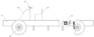
as shown in fig. 6-8, it is a schematic structural diagram of a chassis assembly, which includes road wheels 20, a front axle 29, a rear axle 30, and a frame 37, on which frame 37 a power system 31 and a brake system 33 are mounted for providing power to the rear axle, and at the same time, a steering wheel 32 is provided on the upper end of frame 37 for controlling the front axle to turn, which is mounted through a driving platform 36, and at the front end of which a driver's seat 35 is provided for the operator to operate; the road wheels comprise a front road wheel 38 and a rear road wheel which are arranged on the front and rear axles, and a plurality of control buttons 34 are arranged at the upper end of the driving platform.
After the improvement, the bogie has better override performance in steering and braking, is very convenient even when turning around, can finish the movement in a small range, and is more flexible, thereby overcoming the problems of inconvenient movement, steering and difficult turning around of the traditional bogie.
The utility model relates to a platform truck of pouring anticollision wall, when using, the running gear through the chassis assembly will wholly move to the assigned position, rethread electric block puts down the template, the hanging flower basket is in vertical state this moment, wait the template to install after the assigned position, begin to pour, wait to pour after accomplishing, dismantle outer demoulding oil cylinder and interior demoulding oil cylinder, make its drawing of patterns, the staff gets into the hanging flower basket again, carry out the construction of next step again to the anticollision wall (such as the painting or painting of anticollision wall outer wall, etc.), after accomplishing this process, through outer hand block 23 and interior hand block 22, stimulate outer demoulding oil cylinder 16 and interior demoulding oil cylinder 21 slope upwards respectively, hang other equipment of hindering during preventing moving, so as to move; after the worker goes from the hanging basket to the safe position, the manual hoist is controlled to pull the steel rope, the steel rope turns under the turning of the two pulleys 7, the lower hanging rod is pulled to turn outwards, and therefore the hanging basket is turned outwards, and the whole device can move conveniently; and after the template is demoulded, the template is lifted upwards by the electric hoist and is fixed by the external pull rope to prevent the template from swinging left and right. So that the whole device is driven to the next section by the chassis assembly for continuous construction.
The improvement is passed, the hanging flower basket adopts the jib to install, this jib includes jib and lower jib, go up jib fixed mounting in track roof beam, and the lower extreme is connected with articulated mode in the upper end of jib down, lower jib can be with the outside upset of pivot, thereby drive the outside upset of hanging flower basket, this time the hanging flower basket outside is connected with the steel cable, this steel cable is connected with the hand-operated block and is connected with the winder, stimulate through the hand-operated block, regular through the winder to the steel cable, staff's pulling hand-operated block just can control the hanging flower basket and overturn outward when using, and is simple and fast.
Meanwhile, through improvement, an outer demolding oil cylinder and an inner demolding oil cylinder are respectively arranged on two sides of a template to form a rapid demolding and vertical mold device, the template is fixed through the two oil cylinders, so that the pouring is more stable and reliable, and meanwhile, the two templates are respectively provided with an outer manual hoist and an inner manual hoist, so that the two manual hoists can respectively pull the outer demolding oil cylinder and the inner demolding oil cylinder to be retracted when the whole device moves, and other equipment is prevented from being scratched during moving so as to be convenient to move; meanwhile, the integral demolding and mold erecting of the 10-meter-length template can be realized at one time, and the hoisting device (the electric hoist 4) can ensure the integral group hoisting of the 10-meter-length template. Wherein the single template with the length of 1.0-1.5 meters forms the integral template with the length of 10 meters through the connecting device.
And the utility model discloses can the multiunit template circulation pour, a set of template when pouring, another group's template drawing of patterns, transportation, found the mould. Compared with the traditional construction method in which a single template with the length of 1.0-1.5 meters is operated each time, the trolley greatly improves the construction efficiency;
the previous description of the disclosed embodiments is provided to enable any person skilled in the art to make or use the present invention. Various modifications to these embodiments will be readily apparent to those skilled in the art, and the generic principles defined herein may be applied to other embodiments without departing from the spirit or scope of the invention. Thus, the present invention is not intended to be limited to the embodiments shown herein but is to be accorded the widest scope consistent with the principles and novel features disclosed herein.
Claims (10)
1. The utility model provides a pour platform truck of crashproof wall which characterized in that: including the support body, chassis assembly (12) and hanging flower basket (17), support body fixed mounting is in chassis assembly upper end, the hanging flower basket passes through the jib and hangs in the support body front end to this hanging flower basket can overturn to the outside.
2. The trolley for casting the anti-collision wall as claimed in claim 1, wherein: the anti-collision wall is characterized by further comprising an anti-collision wall die, and an electric hoist (4) for hanging and moving the die is mounted on the frame body.
3. A trolley for casting an anti-collision wall according to claim 1 or 2, characterized in that: the jib includes jib (3) and lower jib (18) of being connected bottom the last jib with articulated mode, go up jib upper end fixed connection in the support body, jib and hanging flower basket fixed connection down to this hanging flower basket is located lower guide arm inboard, has the power device that the jib turned over outwards under the drive through steel cable connection in the jib outside down.
4. The trolley for casting the anti-collision wall as claimed in claim 3, wherein: the frame body comprises a row of front upright post groups formed by a plurality of front upright posts (5) and a row of rear upright post groups formed by a plurality of rear upright posts (10), the adjacent front upright posts and the adjacent rear upright posts are connected through pull rods, and the front upright post groups and the rear upright post groups form a frame body;
the frame body main part top is provided with and stretches over in track roof beam (1) of front column and rear column upper end, the upper end fixed connection of going up the jib is in track roof beam (1).
5. The trolley for casting the anti-collision wall as claimed in claim 4, wherein: the power device for driving the lower suspender to overturn outwards comprises a hoist (8) and a steel rope arranged at the upper end of the chassis assembly (12), wherein the steel rope is connected to the outer side of the lower suspender.
6. The trolley for casting the anti-collision wall as claimed in claim 4, wherein: a gantry support (6) is fixedly arranged between the track beam (1) and the front upright post (5), and an anti-toppling support (14) is arranged at the lower end of the chassis assembly.
7. The trolley for casting the anti-collision wall as claimed in claim 4, wherein: the anti-collision wall mold comprises an inner mold plate (24) and an outer mold plate (25), wherein the upper end and the lower end of the inner mold plate (24) are respectively connected with the outer mold plate (25) through an upper pull rod (28) and a lower pull rod (27).
8. The trolley for casting the anti-collision wall as claimed in claim 7, wherein: an outer demoulding oil cylinder (16) matched with an outer template is arranged on the inner side of the lower suspender (18) in a hinged mode, and an inner demoulding oil cylinder (21) matched with an inner template is arranged on the inner side of the chassis assembly (12) in a hinged mode;
meanwhile, an outer manual hoist (23) for pulling an outer demoulding oil cylinder (16) is arranged on the inner side of the lower suspender (18), and an inner manual hoist (22) for pulling an inner demoulding oil cylinder (21) is arranged on the inner side of the front upright post (5);
the inner demoulding oil cylinder (21), the inner manual hoist (22), the outer demoulding oil cylinder (16) and the outer manual hoist (23) form a quick film erecting and demoulding device of the mould.
9. The trolley for casting the anti-collision wall as claimed in claim 8, wherein: the outer template (25) is provided with a ladder (15) through bolts.
10. The trolley for casting the anti-collision wall as claimed in claim 1, wherein: the upper end of the chassis assembly (12) is provided with a balancing weight (19), and the bottom of the chassis assembly is provided with a travelling wheel (20).
Priority Applications (1)
| Application Number | Priority Date | Filing Date | Title |
|---|---|---|---|
| CN201921484915.9U CN210712555U (en) | 2019-09-09 | 2019-09-09 | Trolley for pouring anti-collision wall |
Applications Claiming Priority (1)
| Application Number | Priority Date | Filing Date | Title |
|---|---|---|---|
| CN201921484915.9U CN210712555U (en) | 2019-09-09 | 2019-09-09 | Trolley for pouring anti-collision wall |
Publications (1)
| Publication Number | Publication Date |
|---|---|
| CN210712555U true CN210712555U (en) | 2020-06-09 |
Family
ID=70937234
Family Applications (1)
| Application Number | Title | Priority Date | Filing Date |
|---|---|---|---|
| CN201921484915.9U Active CN210712555U (en) | 2019-09-09 | 2019-09-09 | Trolley for pouring anti-collision wall |
Country Status (1)
| Country | Link |
|---|---|
| CN (1) | CN210712555U (en) |
-
2019
- 2019-09-09 CN CN201921484915.9U patent/CN210712555U/en active Active
Similar Documents
| Publication | Publication Date | Title |
|---|---|---|
| CN209988965U (en) | Automatic hoisting equipment for sleeper mold in and out of kiln | |
| CN109653105B (en) | Main truss system of box girder bridge cantilever construction hanging basket and use method thereof | |
| CN211142839U (en) | Self-propelled anti-collision wall construction formwork trolley | |
| CN110983951A (en) | Multifunctional anti-collision wall construction trolley and anti-collision wall construction method thereof | |
| CN108002244B (en) | Hoisting system and method for high pier column steel bar formwork | |
| CN215252400U (en) | Self-supporting synchronous hanger system for corrugated steel web construction | |
| CN207877135U (en) | A kind of wheel-track type girder gantry crane | |
| CN210712555U (en) | Trolley for pouring anti-collision wall | |
| CN205638491U (en) | Multi -functional platform truck | |
| CN109384162B (en) | Gantry type component transport vehicle and component transport method | |
| CN210117190U (en) | Small material hoister | |
| CN113137059B (en) | Cast-in-place concrete anti-collision wall movable formwork construction device | |
| CN213538692U (en) | Trolley for guardrail construction | |
| CN214942345U (en) | Construction device for cast-in-place concrete anti-collision wall movable formwork | |
| CN213086579U (en) | Integral moving type bridge formwork maintenance vehicle | |
| CN212687392U (en) | Cable crane hoisting device for bridge erection | |
| CN209854554U (en) | Supplementary car of installing and removing of template | |
| CN203890888U (en) | Girder hoisting traveling crane of single-arm box girder bridge erecting machine | |
| CN211596364U (en) | Multi-functional crashproof wall construction trolley | |
| CN211004232U (en) | Hanging beam crane with floor function | |
| CN111648232A (en) | Bridge cast-in-place concrete anti-collision guardrail template trolley | |
| CN216712773U (en) | Anticollision breast beam construction trolley | |
| CN111115461A (en) | Reinforcing steel bar and mould transportation and automatic assembling equipment | |
| CN220099664U (en) | Intelligent pouring type anti-collision wall template trolley | |
| CN2153536Y (en) | Trackless wheel type crane |
Legal Events
| Date | Code | Title | Description |
|---|---|---|---|
| GR01 | Patent grant | ||
| GR01 | Patent grant |