CN210707645U - Automobile body rear portion structure and car - Google Patents
Automobile body rear portion structure and car Download PDFInfo
- Publication number
- CN210707645U CN210707645U CN201921904300.7U CN201921904300U CN210707645U CN 210707645 U CN210707645 U CN 210707645U CN 201921904300 U CN201921904300 U CN 201921904300U CN 210707645 U CN210707645 U CN 210707645U
- Authority
- CN
- China
- Prior art keywords
- reinforcing plate
- rear wheel
- plate section
- vehicle body
- floor
- Prior art date
- Legal status (The legal status is an assumption and is not a legal conclusion. Google has not performed a legal analysis and makes no representation as to the accuracy of the status listed.)
- Active
Links
Images


Abstract
The application provides a car body rear portion structure and car relates to the technical field of car. The application provides a vehicle body rear structure includes: a cross member, a floor, a rear wheel cover, and a rear wheel cover reinforcement; the cross beam extends along the width direction of the vehicle body, and the end part of the cross beam is connected with the side wall; the floor is connected with the bottom of the cross beam; the rear wheel cover is arranged on one side of the width direction of the vehicle body and is connected with the end part of the cross beam; the rear wheel cover reinforcement is connected with the rear wheel cover; wherein, the rear wheel casing reinforcement includes first reinforcing plate section, second reinforcing plate section and third reinforcing plate section, first reinforcing plate section with the second reinforcing plate section moves towards respectively the floor direction extends, the tip of first reinforcing plate section with the crossbeam is connected, the tip of second reinforcing plate section with the floor is connected, the third reinforcing plate section is followed the rear wheel casing upwards extends to be connected with the side wall, the technical problem that the automobile body that exists among the prior art twists reverse the modal deficiency is alleviated.
Description
Technical Field
The application relates to the technical field of automobiles, in particular to an automobile body rear structure and an automobile.
Background
With the continuous development of the automobile industry and the continuous improvement of the physical living standard of people, automobiles become indispensable transportation tools in daily trips of people. The strength of the body parts of a motor vehicle plays a crucial role in the safety of the entire vehicle body.
In the existing vehicle type, the left and right rear side walls of the rear section of the vehicle body are in lap joint with the floor, and the cross beam is not communicated with the side walls, so that the technical problems of insufficient torsional mode of the vehicle body and poor performance of the whole vehicle are caused.
SUMMERY OF THE UTILITY MODEL
The application provides a vehicle body rear structure and an automobile to alleviate the technical problem that a vehicle body torsion mode is insufficient in the prior art.
The present application provides in a first aspect a vehicle body rear structure including:
the cross beam extends along the width direction of the vehicle body, and the end part of the cross beam is connected with the side wall;
the floor is connected with the bottom of the cross beam;
a rear wheel cover provided on one side in the width direction of the vehicle body and connected to an end of the cross member;
a rear wheel cover reinforcement connected to the rear wheel cover;
the rear wheel cover reinforcement comprises a first reinforcing plate section, a second reinforcing plate section and a third reinforcing plate section, wherein the first reinforcing plate section and the second reinforcing plate section face the floor direction to extend respectively, the end portion of the first reinforcing plate section is connected with the cross beam, the end portion of the second reinforcing plate section is connected with the floor, and the third reinforcing plate section extends upwards along the rear wheel cover and is connected with the side wall.
In one possible design, the side wall, the rear wheel house reinforcement and the cross member form a continuous C-ring structure.
In one possible embodiment, the ends of the first reinforcing plate section are connected to the transverse member by first connecting elements.
In a possible design, a first installation part for installing the seat is arranged on the first conversion piece, and a second installation part for installing the seat is arranged on the cross beam.
In one possible design, the device further comprises a second adapter, and the second adapter is located below the cross beam;
one end of the second adapter is connected with the rear longitudinal beam, and the other end of the second adapter is connected with the floor.
In one possible embodiment, a cavity is formed between the first adapter, the second adapter and the cross member.
In one possible embodiment, the ends of the second reinforcing plate section are connected to the floor panel by means of a third adapter.
In one possible design, the rear wheel cover reinforcement is "Y" shaped or "herringbone" shaped.
In one possible design, the rear wheel house reinforcement is a one-piece structure.
A second aspect of the present application provides an automobile including any one of the vehicle body rear structures.
The technical scheme provided by the application can achieve the following beneficial effects:
the application provides an among the automobile body rear structure, the rear wheel casing reinforcement sets up on the rear wheel casing, first reinforcing plate section and second reinforcing plate section in the rear wheel casing reinforcement extend towards the floor direction respectively, the tip and the crossbeam of first reinforcing plate section are connected, the tip and the floor of second reinforcing plate section are connected, can disperse the load to peripheral automobile body through crossbeam and floor respectively like this, the vibration isolation volume of rear shock absorber mounting point has been improved, thereby greatly reduced in the car rumble and tire noise scheduling problem, the travelling comfort of riding is effectively improved. The third gusset section in the rear wheel house reinforcement extends upward along the rear wheel house, so that the rigidity of the shock absorber mounting point can be increased, and thus, the upward load from the shock absorber can be transmitted to the upper portion of the vehicle body. In addition, the first reinforcing plate section and the second reinforcing plate section can form two force transmission channels, so that the torsional rigidity of the automobile body is effectively improved, and the durability and the safety of the automobile are improved.
It is to be understood that both the foregoing general description and the following detailed description are exemplary and explanatory only and are not restrictive of the application, as provided.
Drawings
In order to more clearly illustrate the technical solutions of the embodiments of the present application, the drawings needed to be used in the embodiments will be briefly described below, and it is obvious that the drawings in the following description are only some embodiments of the present application, and it is obvious for those skilled in the art to obtain other drawings based on these drawings without creative efforts.
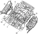
FIG. 1 is a schematic structural view of a rear structure of a vehicle body according to an embodiment of the present application;
FIG. 2 is a schematic bottom view of a rear structure of a vehicle body provided in an embodiment of the present application;
FIG. 3 is a schematic structural view of a rear wheel house reinforcement in the vehicle body rear structure according to the embodiment of the present application;
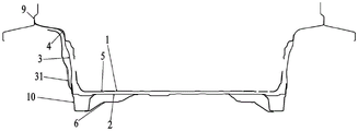
FIG. 4 is a schematic structural view in section;
fig. 5 is a schematic structural view of a cross section of a seat.
Reference numerals:
1-a cross beam;
2-floor board;
3-rear wheel cover;
31-damper mounting section;
4-rear wheel cover reinforcement;
41-a first stiffener section;
42-a second stiffener section;
43-a third stiffener section;
5-a first transfer member;
6-a second adaptor;
7-a third adaptor;
8-a seat;
9-side wall;
10-longitudinal beam.
The accompanying drawings, which are incorporated in and constitute a part of this specification, illustrate embodiments consistent with the present application and together with the description, serve to explain the principles of the application.
Detailed Description
For better understanding of the technical solutions of the present application, the following detailed descriptions of the embodiments of the present application are provided with reference to the accompanying drawings.
It should be understood that the embodiments described are only a few embodiments of the present application, and not all embodiments. All other embodiments, which can be derived by a person skilled in the art from the embodiments given herein without making any creative effort, shall fall within the protection scope of the present application.
The terminology used in the embodiments of the present application is for the purpose of describing particular embodiments only and is not intended to be limiting of the application. As used in the examples of this application and the appended claims, the singular forms "a", "an", and "the" are intended to include the plural forms as well, unless the context clearly indicates otherwise.
It should be understood that the term "and/or" as used herein is merely one type of association that describes an associated object, meaning that three relationships may exist, e.g., a and/or B may mean: a exists alone, A and B exist simultaneously, and B exists alone. In addition, the character "/" herein generally indicates that the former and latter related objects are in an "or" relationship.
It should be noted that the terms "upper", "lower", "left", "right", and the like used in the embodiments of the present application are described in terms of the angles shown in the drawings, and should not be construed as limiting the embodiments of the present application. In addition, in this context, it will also be understood that when an element is referred to as being "on" or "under" another element, it can be directly on "or" under "the other element or be indirectly on" or "under" the other element via an intermediate element.
Example one
As shown in fig. 1, 2, 3, 4, and 5, a vehicle body rear structure provided by an embodiment of the present application includes: a cross beam 1, a floor 2, a rear wheel cover 3 and a rear wheel cover reinforcement 4; the cross beam 1 extends along the width direction of the vehicle body, and the end part of the cross beam is connected with the side wall 9, and particularly can be connected by welding; the floor 2 is connected with the bottom of the cross beam 1, and particularly can be connected through welding; the rear wheel cover 3 is arranged on one side of the width direction of the vehicle body, is connected with the end part of the cross beam 1, and can be connected through welding specifically; the rear wheel cover reinforcement 4 is connected with the rear wheel cover 3, and specifically can be connected by welding; wherein, rear wheel casing reinforcement 4 includes first reinforcing plate section 41, second reinforcing plate section 42 and third reinforcing plate section 43, and first reinforcing plate section 41 and second reinforcing plate section 42 extend towards floor 2 direction respectively, and the tip of first reinforcing plate section 41 is connected with crossbeam 1, and the tip of second reinforcing plate section 42 is connected with floor 2, and third reinforcing plate section 43 extends along rear wheel casing 3 to be connected with side wall 9.
In the vehicle body rear structure provided by the present application, the rear wheel house reinforcement 4 is provided on the rear wheel house 3, and the third gusset section 43 extends upward along the rear wheel house 3, so that the rigidity of the shock absorber mounting point can be improved, and thus, the load from the shock absorber upward can be transmitted to the vehicle body upper portion. The first reinforcing plate section 41 and the second reinforcing plate section 42 in the rear wheel cover reinforcement 4 extend towards the direction of the floor 2 respectively, the end part of the first reinforcing plate section 41 is connected with the cross beam 1, and the end part of the second reinforcing plate section 42 is connected with the floor 2, so that loads can be dispersed to a peripheral vehicle body through the cross beam 1 and the floor 2 respectively, the vibration isolation amount of a rear shock absorber mounting point is improved, the problems of roaring, tire noise and the like in a vehicle are greatly reduced, the riding comfort is effectively improved, the first reinforcing plate section 41 and the second reinforcing plate section 42 can form two force transmission channels, the forces are transmitted to the cross beam and the floor, the torsional rigidity of the vehicle body is effectively improved, and the durability and the safety of the vehicle are improved.
Alternatively, the rear wheel house reinforcement 4 may be fixed to the plate of the rear wheel house 3 by welding.
Be equipped with bumper shock absorber installation department 31 on the rear wheel casing 3, the bumper shock absorber can be through welded fastening on the inner panel of rear wheel casing 3, because be equipped with rear wheel casing reinforcement 4 on the 3 inner panels of rear wheel casings, consequently, it can improve the dynamic stiffness level of bumper shock absorber installation point, can effectively reduce the vibration that comes from the road surface, promotes the road noise level of automobile body.
As shown in fig. 4, the side wall 9, the rear wheel cover reinforcement 4 and the cross beam 1 form a continuous C-ring structure, and the rigidity level of the C-ring structure can be further improved by arranging the rear wheel cover reinforcement 4, so that the performance of the whole vehicle is improved. In addition, the rear wheel cover reinforcement 4, the rear wheel cover 3, the first adapter 5, the second adapter 6, the cross beam 1, the floor 2 and the side wall 9 form a cavity together, so that a closed C ring is formed, and the performance of the whole vehicle is improved.
In a specific embodiment, the end of the first reinforcing plate section 41 is connected with the cross beam 1 through the first adaptor 5, the first adaptor 5 plays a role in structural reinforcement, and the rear wheel cover reinforcing piece 4 and the cross beam 1 are matched, so that the torsional rigidity of the vehicle body can be improved, and the durability and the safety of the automobile can be improved. The first adapter 5 may be an adapter plate, adapter bracket adapter or the like.
In a specific embodiment, be equipped with the first installation department that is used for installing seat 8 on the first adaptor 5, be equipped with the second installation department that is used for installing seat 8 on the crossbeam 1, can arrange first adaptor 5 and crossbeam 1 in seat 8 below, avoided the defect of adapter bracket, promoted man-machine travelling comfort.
In a specific embodiment, the device further comprises a second adapter piece 6, wherein the second adapter piece 6 is positioned below the cross beam 1; one end of the second adapter piece 6 is connected with the rear longitudinal beam 10, and the other end is connected with the floor 2. The second adapter 6 plays a role in structural reinforcement and is matched with the rear wheel cover reinforcement 4 and the cross beam 1, so that the torsional rigidity of the automobile body can be improved, and the durability and the safety of the automobile can be improved. The second adaptor 6 may be an adaptor plate, an adaptor bracket adaptor, or the like.
As shown in fig. 5, a cavity is formed between the first adaptor 5, the second adaptor 6 and the beam 1. The rigidity and the vibration resistance of the cross beam 1 of the rear floor 2 can be improved by utilizing a composite section structure formed among the first adapter 5, the second adapter 6 and the cross beam 1.
In a specific embodiment, the end of the second gusset section 42 is connected to the floor panel 2 by a third adapter 7. Through the third adaptor 7, the structure is reinforced, and the torsional rigidity of the automobile body can be improved by matching the rear wheel cover reinforcement 4 with the cross beam 1, and the durability and the safety of the automobile are improved. The third adapter 7 may be an adapter plate, adapter bracket adapter or the like.
As shown in fig. 3, the rear wheel cover reinforcement 4 is Y-shaped or herringbone, the upper part is lapped with the side wall 9 inner plate, the lower end is connected with the left and right first transition pieces 5 to form a performance cavity, the C ring is sealed, and the performance of the whole vehicle is greatly improved, so that the torsion mode of the body-in-white can reach 36.5Hz, the mounting point of the rear shock absorber can reach 8500N/mm.
Example two
The automobile provided by the second embodiment comprises the automobile body rear structure provided by any one technical scheme of the second embodiment. The structure and the beneficial effects of the vehicle body rear structure are described in detail in the first embodiment, and are not described again here. The automobile and the vehicle body rear structure provided by the first embodiment have the same advantages compared with the prior art, and are not described herein again.
The above description is only a preferred embodiment of the present application and is not intended to limit the present application, and various modifications and changes may be made by those skilled in the art. Any modification, equivalent replacement, improvement and the like made within the spirit and principle of the present application shall be included in the protection scope of the present application.
Claims (10)
1. A vehicle body rear structure characterized by comprising:
the cross beam extends along the width direction of the vehicle body, and the end part of the cross beam is connected with the side wall;
the floor is connected with the bottom of the cross beam;
a rear wheel cover provided on one side in the width direction of the vehicle body and connected to an end of the cross member;
a rear wheel cover reinforcement connected to the rear wheel cover;
the rear wheel cover reinforcement comprises a first reinforcing plate section, a second reinforcing plate section and a third reinforcing plate section, wherein the first reinforcing plate section and the second reinforcing plate section face the floor direction to extend respectively, the end portion of the first reinforcing plate section is connected with the cross beam, the end portion of the second reinforcing plate section is connected with the floor, and the third reinforcing plate section extends upwards along the rear wheel cover and is connected with the side wall.
2. The vehicle body rear structure according to claim 1, wherein the side body, the rear wheel house reinforcement, and the cross member form a continuous C-ring structure.
3. The vehicle body rear structure according to claim 1 or 2, characterized in that an end of the first gusset section and the cross member are connected by a first joint member.
4. The vehicle body rear structure according to claim 3, wherein a first mounting portion for mounting a seat is provided on the first joint member, and a second mounting portion for mounting a seat is provided on the cross member.
5. The vehicle body rear structure according to claim 4, further comprising a second adapter located below the cross member;
one end of the second adapter is connected with the rear longitudinal beam, and the other end of the second adapter is connected with the floor.
6. The vehicle body rear structure according to claim 5, characterized in that a cavity is formed between the first adapter, the second adapter, and the cross member.
7. The vehicle body rear structure according to claim 1 or 2, characterized in that an end of the second gusset section is connected to the floor panel by a third adapter.
8. The vehicle body rear structure according to claim 1 or 2, wherein the rear wheel house reinforcement is "Y" shaped or "herringbone" shaped.
9. The vehicle body rear structure according to claim 1 or 2, characterized in that the rear wheel house reinforcement is a one-piece structure.
10. An automobile characterized by comprising the vehicle body rear structure according to any one of claims 1 to 9.
Priority Applications (1)
| Application Number | Priority Date | Filing Date | Title |
|---|---|---|---|
| CN201921904300.7U CN210707645U (en) | 2019-11-06 | 2019-11-06 | Automobile body rear portion structure and car |
Applications Claiming Priority (1)
| Application Number | Priority Date | Filing Date | Title |
|---|---|---|---|
| CN201921904300.7U CN210707645U (en) | 2019-11-06 | 2019-11-06 | Automobile body rear portion structure and car |
Publications (1)
| Publication Number | Publication Date |
|---|---|
| CN210707645U true CN210707645U (en) | 2020-06-09 |
Family
ID=70967631
Family Applications (1)
| Application Number | Title | Priority Date | Filing Date |
|---|---|---|---|
| CN201921904300.7U Active CN210707645U (en) | 2019-11-06 | 2019-11-06 | Automobile body rear portion structure and car |
Country Status (1)
| Country | Link |
|---|---|
| CN (1) | CN210707645U (en) |
Cited By (1)
| Publication number | Priority date | Publication date | Assignee | Title |
|---|---|---|---|---|
| CN114954682A (en) * | 2022-06-06 | 2022-08-30 | 浙江吉利控股集团有限公司 | Rear wheel casing skeleton and vehicle of vehicle |
-
2019
- 2019-11-06 CN CN201921904300.7U patent/CN210707645U/en active Active
Cited By (2)
| Publication number | Priority date | Publication date | Assignee | Title |
|---|---|---|---|---|
| CN114954682A (en) * | 2022-06-06 | 2022-08-30 | 浙江吉利控股集团有限公司 | Rear wheel casing skeleton and vehicle of vehicle |
| CN114954682B (en) * | 2022-06-06 | 2023-08-04 | 浙江吉利控股集团有限公司 | Rear wheel cover framework of vehicle and vehicle |
Similar Documents
| Publication | Publication Date | Title |
|---|---|---|
| US8641131B2 (en) | Frame structure for vehicle | |
| CN201895705U (en) | Forecabin structure of automobile body | |
| CN204998609U (en) | Longeron assembly and car behind car | |
| JPS6256820B2 (en) | ||
| EP1852335A1 (en) | Device for reinforcing vehicle body of vehicle | |
| CN203623797U (en) | Car cab rear wall reinforcing structure | |
| CN212950847U (en) | Rear side wall reinforcing frame assembly | |
| CN210707645U (en) | Automobile body rear portion structure and car | |
| CN216140071U (en) | Rear side wall structure and vehicle | |
| CN102765423B (en) | Vehicle frame and engineering truck | |
| CN110588798A (en) | Rear shock absorption seat and automobile | |
| CN215285013U (en) | Regional additional strengthening of rear wheel casing and have its vehicle | |
| CN114802484A (en) | Rear floor structure of electric automobile | |
| CN212637074U (en) | Rear shock absorber mounting plate and rear shock absorber mounting assembly | |
| CN210634646U (en) | Bending rigidity reinforcing structure for floor beam of electric automobile | |
| CN205365741U (en) | Back suspension mounting structure and automobile | |
| CN210309809U (en) | Leaf spring fixing device for lorry | |
| CN103381855B (en) | A kind of connection reinforcing structure improving automotive floor panel rigidity | |
| CN215155053U (en) | Rear wheel casing subassembly and car of car | |
| CN205737702U (en) | A kind of MPV (Multi-Purpose Vehicle) chassis system | |
| CN220374214U (en) | Spiral spring automobile body side mounting point reinforced structure and car | |
| CN216994536U (en) | Automobile body side wall structure and car | |
| CN219821584U (en) | Front floor assembly structure of new energy automobile and automobile | |
| CN210653051U (en) | Brake pedal arm for vehicle | |
| CN215245130U (en) | Rear suspension mounting structure and car |
Legal Events
| Date | Code | Title | Description |
|---|---|---|---|
| GR01 | Patent grant | ||
| GR01 | Patent grant | ||
| TR01 | Transfer of patent right | ||
| TR01 | Transfer of patent right |
Effective date of registration: 20220715 Address after: 401135 No. 618 Liangjiang Avenue, Longxing Town, Yubei District, Chongqing Patentee after: Chongqing Jin Kang Sai Li Si New Energy Automobile Design Institute Co.,Ltd. Address before: 402260 No.1 Jiujiang Avenue, Shuangfu New District, Shapingba District, Chongqing Patentee before: CHONGQING BRANCH, DFSK AUTOMOBILE Co.,Ltd. |