CN210706875U - New energy automobile radiator convenient to installation - Google Patents
New energy automobile radiator convenient to installation Download PDFInfo
- Publication number
- CN210706875U CN210706875U CN201921683470.7U CN201921683470U CN210706875U CN 210706875 U CN210706875 U CN 210706875U CN 201921683470 U CN201921683470 U CN 201921683470U CN 210706875 U CN210706875 U CN 210706875U
- Authority
- CN
- China
- Prior art keywords
- columns
- new energy
- energy automobile
- radiator
- radiator body
- Prior art date
- Legal status (The legal status is an assumption and is not a legal conclusion. Google has not performed a legal analysis and makes no representation as to the accuracy of the status listed.)
- Expired - Fee Related
Links
Images

Landscapes
- Cooling, Air Intake And Gas Exhaust, And Fuel Tank Arrangements In Propulsion Units (AREA)
Abstract
The utility model belongs to the technical field of the radiator, especially, be a new energy automobile radiator convenient to installation, which comprises a mounting bracket, two draw-in grooves have all been seted up on the both sides inner wall of mounting bracket, be equipped with the radiator body on the mounting bracket, the top and the equal fixed mounting in bottom of radiator body have the crossbeam, the inner chamber has been seted up on the crossbeam, the hole of dodging has all been seted up to the both sides inner wall of inner chamber, the intracavity is equipped with two and removes the post, the top of removing the post extends to outside the crossbeam, the intracavity is equipped with two card posts, and the one end that two card posts are close to each other removes post fixed connection with two respectively, and the one end that two card posts kept away from each other runs through two respectively and dod. The utility model relates to a rationally, through the removal post that sets up, card post and draw-in groove just can be quick reliably fix the radiator body, easy operation, convenient and practical.
Description
Technical Field
The utility model relates to a radiator technical field especially relates to a new energy automobile radiator convenient to installation.
Background
The new energy automobile is an automobile which adopts unconventional automobile fuel as a power source, integrates advanced technologies in the aspects of power control and driving of the automobile, forms an advanced technical principle, has a new technology and a new structure, and is the same as a common automobile in the aspect of heat dissipation of the interior of the automobile, particularly a hydrogen energy automobile which can dissipate a large amount of heat in the running process and needs a radiator for heat dissipation.
However, the traditional radiator still has more problems when using, and basically all fix the radiator in the car through bolt fastening or welded mode, and it is comparatively inconvenient to install, has brought the difficulty when dismantling the quick maintenance in later stage, for this reason, provides a new energy automobile radiator convenient to installation.
SUMMERY OF THE UTILITY MODEL
The utility model aims at solving the defects existing in the prior art and providing a new energy automobile radiator convenient to install.
In order to achieve the above purpose, the utility model adopts the following technical scheme: a new energy automobile radiator convenient to install comprises a mounting frame, wherein two clamping grooves are formed in the inner walls of two sides of the mounting frame, a radiator body is arranged on the mounting frame, a cross beam is fixedly mounted at the top and the bottom of the radiator body, an inner cavity is formed in the cross beam, avoidance holes are formed in the inner walls of two sides of the inner cavity, two movable columns are arranged in the inner cavity, the top ends of the movable columns extend out of the cross beam, two clamping columns are arranged in the inner cavity, the ends, close to each other, of the two clamping columns are fixedly connected with the two movable columns respectively, the ends, far away from each other, of the two clamping columns penetrate through the two avoidance holes respectively and extend into the corresponding clamping grooves, springs are sleeved on the clamping columns, the ends, close to each other, of the two springs are fixedly connected with the two movable columns respectively, and the ends, far away, the radiator comprises a radiator body, a crossbeam, two fixed blocks, a movable column and a cross rod, wherein the crossbeam is symmetrically and fixedly provided with the two fixed blocks at one side far away from the radiator body, one side where the two fixed blocks are close to each other is fixedly provided with the same cross rod, and the movable column is connected with the cross rod in a sliding manner.
Preferably, two fixing plates are fixedly mounted on the outer walls of the two sides of the mounting frame, and mounting holes are formed in the fixing plates.
Preferably, a rectangular frame opening is formed in the inner cavity, and the movable column penetrates through the rectangular frame opening.
Preferably, bearing holes are formed in the two movable columns, the two linear bearings are sleeved on the cross beam in a sliding mode, and the inner walls of the two bearing holes are fixedly connected with the outer rings of the two linear bearings respectively.
Preferably, the arc-shaped grooves are formed in the sides, far away from each other, of the two moving columns, and anti-slip pads are arranged in the arc-shaped grooves.
Preferably, the transverse rod is fixedly sleeved with a spacer bush.
Compared with the prior art, the beneficial effects of the utility model are that: firstly, the device is matched with a mounting frame, a radiator body, a cross beam, an inner cavity, moving columns, clamping columns, a spring, avoidance holes, clamping grooves, a fixed block, a cross rod and a fixed plate, when the device is used, the mounting frame and the radiator body are fixed in a vehicle, the two corresponding moving columns are pressed and move in opposite directions, the clamping columns are driven by the moving columns to move in a direction away from the clamping grooves, the spring can stretch and deform, the radiator body can be taken out after the clamping columns completely leave the clamping grooves, and similarly, when the radiator body is fixed, the two corresponding moving columns only need to be pressed and move in opposite directions, then the radiator body is placed in the mounting frame, then the two corresponding moving columns are sequentially loosened, and the clamping columns are clamped into the clamping grooves under the action of the spring, so that the installation of the radiator body is finished;
the utility model relates to a rationally, through the removal post that sets up, card post and draw-in groove just can be quick reliably fix the radiator body, easy operation, convenient and practical.
Drawings
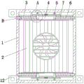
Fig. 1 is a schematic view of the structure of the present invention;
FIG. 2 is an enlarged schematic view of the structure at A in FIG. 1;
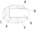
fig. 3 is an enlarged schematic view of a portion B in fig. 1.
In the figure: 1. a mounting frame; 2. a heat sink body; 3. a cross beam; 4. an inner cavity; 5. moving the column; 6. clamping the column; 7. a spring; 8. avoiding holes; 9. a card slot; 10. a fixed block; 11. a cross bar; 12. and (7) fixing the plate.
Detailed Description
The technical solutions in the embodiments of the present invention will be described clearly and completely with reference to the accompanying drawings in the embodiments of the present invention, and it is obvious that the described embodiments are only some embodiments of the present invention, not all embodiments. Based on the embodiments in the present invention, all other embodiments obtained by a person skilled in the art without creative work belong to the protection scope of the present invention.
Referring to fig. 1 to fig. 3, the present invention provides a technical solution: a new energy automobile radiator convenient to install comprises a mounting frame 1, two clamping grooves 9 are formed in the inner walls of two sides of the mounting frame 1, a radiator body 2 is arranged on the mounting frame 1, a cross beam 3 is fixedly mounted at the top and the bottom of the radiator body 2, an inner cavity 4 is formed in the cross beam 3, avoidance holes 8 are formed in the inner walls of two sides of the inner cavity 4, two moving columns 5 are arranged in the inner cavity 4, the top ends of the moving columns 5 extend out of the cross beam 3, two clamping columns 6 are arranged in the inner cavity 4, the ends, close to each other, of the two clamping columns 6 are fixedly connected with the two moving columns 5 respectively, the ends, far away from each other, of the two clamping columns 6 penetrate through the two avoidance holes 8 respectively and extend into the corresponding clamping grooves 9, springs 7 are sleeved on the clamping columns 6, the ends, close to each other, of the two springs 7 are fixedly connected with the two moving columns 5 respectively, two fixing blocks 10 are symmetrically and fixedly installed on one side, far away from the radiator body 2, of the cross beam 3, one side, close to each other, of each fixing block 10 is fixedly installed with a cross rod 11, and the moving column 5 is connected with the cross rod 11 in a sliding mode;
two fixed plates 12 are fixedly arranged on the outer walls of two sides of the mounting frame 1, mounting holes are formed in the fixed plates 12, a rectangular frame opening is formed in the inner cavity 4, the moving columns 5 penetrate through the rectangular frame opening, bearing holes are formed in the two moving columns 5, two linear bearings are slidably sleeved on the cross beam 3, the inner walls of the two bearing holes are fixedly connected with the outer rings of the two linear bearings respectively, arc grooves are formed in the sides, away from each other, of the two moving columns 5, anti-slip pads are arranged in the arc grooves, spacer sleeves are fixedly sleeved on the cross rod 11, the mounting frame 1, the radiator body 2, the cross beam 3, the inner cavity 4, the moving columns 5, the clamping columns 6, the springs 7, the avoidance holes 8, the clamping grooves 9, the fixed blocks 10, the cross rod 11 and the fixed plates 12 are matched, when the mounting frame 1 and the radiator body 2 are fixed in a vehicle, the two corresponding moving, remove post 5 and just drive the direction motion of card post 6 toward keeping away from draw-in groove 9, spring 7 just can tensile deformation, leave draw-in groove 9 back completely until calorie post 6, just can take out radiator body 2, and on the same reason, when fixing radiator body 2, only need press two removal posts 5 that correspond and do the motion in opposite directions, then place radiator body 2 in mounting bracket 2, then loosen two removal posts 5 that correspond in proper order, under spring 7's effect, card post 6 just blocks into in draw-in groove 9 to finish the installation to radiator body 2, the utility model relates to a rationally, through the removal post 5 that sets up, card post 6 and draw-in groove 9 just can be quick reliably fixed radiator body 2, easy operation, convenient and practical.
The working principle is as follows: when the radiator is used, the mounting frame 1 and the radiator body 2 are fixed in a vehicle through the four mounting holes, when the radiator body 2 needs to be detached, the corresponding two movable columns 5 are pressed and move in opposite directions, the movable columns 5 start to slide, so that the clamping columns 6 are driven to move in the direction away from the clamping grooves 9, at the moment, the springs 7 are stretched and deformed under the action of tensile force until the clamping columns 6 completely leave the clamping grooves 9, the radiator body 2 can be taken out from the mounting frame 1, similarly, when the radiator body 2 needs to be fixed on the mounting frame 1, the corresponding two movable columns 5 only need to be pressed and move in opposite directions, then the radiator body 2 is placed in the mounting frame 2, the four clamping columns 6 are aligned with the corresponding clamping grooves 9, then the corresponding two movable columns 5 are sequentially loosened, and under the action of the springs 7, the clamping columns 6 can be clamped into the clamping grooves 9, after the four clamping columns 6 are clamped into the corresponding clamping grooves 9, the radiator body 2 is installed.
The above, only be the concrete implementation of the preferred embodiment of the present invention, but the protection scope of the present invention is not limited thereto, and any person skilled in the art is in the technical scope of the present invention, according to the technical solution of the present invention and the utility model, the concept of which is equivalent to replace or change, should be covered within the protection scope of the present invention.
Claims (6)
1. The utility model provides a new energy automobile radiator convenient to installation, includes mounting bracket (1), its characterized in that: the heat radiator is characterized in that two clamping grooves (9) are formed in the inner walls of two sides of the mounting frame (1), a radiator body (2) is arranged on the mounting frame (1), a cross beam (3) is fixedly arranged at the top and the bottom of the radiator body (2), an inner cavity (4) is formed in the cross beam (3), avoidance holes (8) are formed in the inner walls of two sides of the inner cavity (4), two movable columns (5) are arranged in the inner cavity (4), the top ends of the movable columns (5) extend out of the cross beam (3), two clamping columns (6) are arranged in the inner cavity (4), one ends, close to each other, of the two clamping columns (6) are fixedly connected with the two movable columns (5) respectively, one ends, far away from each other, of the two clamping columns (6) penetrate through the avoidance holes (8) respectively and extend into the corresponding clamping grooves (9), and springs (7) are sleeved on the, one end that two springs (7) are close to each other respectively with two removal post (5) fixed connection, the one end that two springs (7) were kept away from each other respectively with the both sides inner wall fixed connection of inner chamber (4), one side symmetry fixed mounting that radiator body (2) were kept away from in crossbeam (3) has two fixed blocks (10), one side fixed mounting that two fixed blocks (10) are close to each other has same horizontal pole (11), remove post (5) and horizontal pole (11) sliding connection.
2. The new energy automobile radiator convenient to install of claim 1, characterized in that: two fixing plates (12) are fixedly mounted on the outer walls of the two sides of the mounting rack (1), and mounting holes are formed in the fixing plates (12).
3. The new energy automobile radiator convenient to install of claim 1, characterized in that: a rectangular frame opening is formed in the inner cavity (4), and the moving column (5) penetrates through the rectangular frame opening.
4. The new energy automobile radiator convenient to install of claim 1, characterized in that: bearing holes are formed in the two movable columns (5), the two linear bearings are sleeved on the cross beam (3) in a sliding mode, and the inner walls of the two bearing holes are fixedly connected with the outer rings of the two linear bearings respectively.
5. The new energy automobile radiator convenient to install of claim 1, characterized in that: arc-shaped grooves are formed in one sides, far away from each other, of the two moving columns (5), and anti-slip pads are arranged in the arc-shaped grooves.
6. The new energy automobile radiator convenient to install of claim 1, characterized in that: the transverse rod (11) is fixedly sleeved with a spacer bush.
Priority Applications (1)
| Application Number | Priority Date | Filing Date | Title |
|---|---|---|---|
| CN201921683470.7U CN210706875U (en) | 2019-10-10 | 2019-10-10 | New energy automobile radiator convenient to installation |
Applications Claiming Priority (1)
| Application Number | Priority Date | Filing Date | Title |
|---|---|---|---|
| CN201921683470.7U CN210706875U (en) | 2019-10-10 | 2019-10-10 | New energy automobile radiator convenient to installation |
Publications (1)
| Publication Number | Publication Date |
|---|---|
| CN210706875U true CN210706875U (en) | 2020-06-09 |
Family
ID=70930386
Family Applications (1)
| Application Number | Title | Priority Date | Filing Date |
|---|---|---|---|
| CN201921683470.7U Expired - Fee Related CN210706875U (en) | 2019-10-10 | 2019-10-10 | New energy automobile radiator convenient to installation |
Country Status (1)
| Country | Link |
|---|---|
| CN (1) | CN210706875U (en) |
Cited By (2)
| Publication number | Priority date | Publication date | Assignee | Title |
|---|---|---|---|---|
| CN112389191A (en) * | 2020-11-23 | 2021-02-23 | 无锡职业技术学院 | Automobile cooling fan |
| CN117704852A (en) * | 2024-01-15 | 2024-03-15 | 缙云县盛大实业有限公司 | Steel plate radiator |
-
2019
- 2019-10-10 CN CN201921683470.7U patent/CN210706875U/en not_active Expired - Fee Related
Cited By (2)
| Publication number | Priority date | Publication date | Assignee | Title |
|---|---|---|---|---|
| CN112389191A (en) * | 2020-11-23 | 2021-02-23 | 无锡职业技术学院 | Automobile cooling fan |
| CN117704852A (en) * | 2024-01-15 | 2024-03-15 | 缙云县盛大实业有限公司 | Steel plate radiator |
Similar Documents
| Publication | Publication Date | Title |
|---|---|---|
| CN210706875U (en) | New energy automobile radiator convenient to installation | |
| CN207981894U (en) | A kind of correcting tool of anti-carriage deformation | |
| CN209756151U (en) | Double-station hydraulic press | |
| CN211276231U (en) | Quick mould dismounting device | |
| CN211161834U (en) | Quick detachable stop gate of injection position of die casting machine | |
| CN211637897U (en) | Punching machine is used in automobile parts processing | |
| CN215329374U (en) | Road and bridge construction template fixing mechanism | |
| CN221312065U (en) | Automobile window aluminum guide rail stamping device | |
| CN216462188U (en) | Clamping device for clamping circular section bar in vertical V-shaped manner | |
| CN210450538U (en) | Automobile header punching tool | |
| CN215267194U (en) | Power distribution cabinet stand column clamping tool | |
| CN212484817U (en) | LED display screen module of quick installation | |
| CN212946571U (en) | Clamping device for machining shaft box | |
| CN211496812U (en) | Pneumatic trench lifter | |
| CN214924056U (en) | Membrane head dismounting device for diaphragm type hydrogen compressor | |
| CN215845515U (en) | Molding sand processing apparatus is used in automobile casting production | |
| CN213531748U (en) | Clamping device for quick clamp | |
| CN214351907U (en) | Clamp for machining automobile mold | |
| CN216829711U (en) | Piston rod end face hole machining tool | |
| CN220814447U (en) | Assembled curtain mounting structure | |
| CN215617699U (en) | High-speed railway wheel rolling mill hollow shaft box installation frock | |
| CN217121407U (en) | Easy maintenance's auto parts stamping device | |
| CN213288371U (en) | Automobile mold dismounting structure | |
| CN219623205U (en) | Novel transfer case | |
| CN216734173U (en) | Automobile front bumper connecting structure |
Legal Events
| Date | Code | Title | Description |
|---|---|---|---|
| GR01 | Patent grant | ||
| GR01 | Patent grant | ||
| CF01 | Termination of patent right due to non-payment of annual fee |
Granted publication date: 20200609 Termination date: 20211010 |
|
| CF01 | Termination of patent right due to non-payment of annual fee |