CN210703442U - Automatic assembling device for sealing ring for plug of brake alarm - Google Patents
Automatic assembling device for sealing ring for plug of brake alarm Download PDFInfo
- Publication number
- CN210703442U CN210703442U CN201921535850.6U CN201921535850U CN210703442U CN 210703442 U CN210703442 U CN 210703442U CN 201921535850 U CN201921535850 U CN 201921535850U CN 210703442 U CN210703442 U CN 210703442U
- Authority
- CN
- China
- Prior art keywords
- cylinder
- sealing ring
- piston rod
- plug
- feeding
- Prior art date
- Legal status (The legal status is an assumption and is not a legal conclusion. Google has not performed a legal analysis and makes no representation as to the accuracy of the status listed.)
- Active
Links
Images


Abstract
The utility model relates to an automatic assembling device of a sealing ring for a plug of a brake alarm, which comprises a control device and a turntable which can rotate along the axis of the turntable, wherein the turntable is arranged on the upper surface of a workbench, and a plurality of positioning groove bodies are uniformly distributed on the upper surface of the turntable along the circumferential direction; a first vibration feeding disc, a second vibration feeding disc, an extrusion device, a detection device and a discharging device are sequentially arranged on the outer side of the rotary disc along a set rotary direction; the first vibration feeding disc can convey the plugs stored in the first vibration feeding disc to a first feeding device according to a set posture, and the first feeding device can convey the plugs to adjacent positioning groove bodies; the second vibration feeding disc can convey the sealing rings stored in the second vibration feeding disc to the second feeding device according to a set posture. The utility model discloses can realize the automatic assembly of plug and sealing washer for the brake alarm, improve assembly efficiency when using manpower sparingly.
Description
Technical Field
The utility model belongs to the technical field of brake alarm rigging equipment, concretely relates to brake alarm is sealing washer automatic assembly device for plug.
Background
The inventor knows, and brake alarm's detection plug need install the sealing washer when the assembly, and the assembly of current plug and sealing washer is manual assembly, and operating personnel holds the plug in one hand, holds the sealing washer in one hand, packs into the sealing washer the plug inside and push the plug bottom to the sealing washer with pushing away the circle instrument. The manual assembly has more assembling actions, the tools are frequently taken, and the labor is wasted; and the production efficiency is low, and the method is difficult to be suitable for mass production.
SUMMERY OF THE UTILITY MODEL
The utility model aims at providing a brake alarm is sealing washer automatic assembly device for plug can realize the automatic assembly of plug for the brake alarm and sealing washer, improves assembly efficiency when using manpower sparingly.
In order to achieve the above purpose, the utility model adopts the following technical scheme: the utility model provides a brake alarm is sealing washer automatic assembly device for plug, includes controlling means and can follow self axis pivoted carousel, the carousel sets up in the upper surface of workstation, the upper surface of carousel is equipped with a plurality of location cell bodies along the circumferencial direction equipartition.
The outer side of the rotary disc is sequentially provided with a first vibration feeding disc, a second vibration feeding disc, an extrusion device, a detection device and a discharging device along a set rotary direction.
The first vibration feeding disc can convey plugs stored in the first vibration feeding disc to a first feeding device according to set postures, and the first feeding device can convey the plugs to adjacent positioning groove bodies.
The second vibration feeding disc can convey the sealing rings stored in the second vibration feeding disc to a second feeding device according to set postures, and the second feeding device can convey the sealing rings to the positions above the adjacent plugs and realize the primary positioning of the plugs and the sealing rings.
The lower end of the pressing device can move up and down to press the sealing ring into the plug completely.
The detection device can detect the pressing depth of the sealing ring and the plug.
The blanking device comprises a blanking cylinder fixedly arranged with the workbench, a first push head is arranged at a piston rod of the blanking cylinder, and the first push head can push out a plug and a sealing ring which are detected by the detection device from the positioning groove body.
The control device can control the rotary disc to rotate and judge whether the assembly of the plug and the sealing ring is qualified or not according to the signal of the detection device.
Further, a first straight channel of the first vibration feeding disc is communicated with a first feeding device; and a second straight material channel of the second vibration feeding disc is communicated with a second feeding device.
Furthermore, the middle part of the rotary table is provided with a rotating shaft, the rotating shaft is fixedly connected with an output shaft of the driving motor, and the output shaft of the driving motor is vertically and upwards arranged.
Further, the first feeding device comprises a second air cylinder fixed with the workbench, an output shaft of the second air cylinder is vertically and upwards arranged, a feeding seat is arranged at the upper end of a piston rod in the second air cylinder, and a clamping groove is formed in the feeding seat and used for accommodating a plug fed from the first straight material channel.
The upper end fixedly connected with balladeur train of second cylinder, the inner chamber lift of balladeur train can be followed to the pay-off seat, the top of balladeur train is equipped with the discharge gate, the upper end of balladeur train is fixed and is equipped with first cylinder, the shell and the balladeur train fixed connection of first cylinder, the piston rod end and the fourth of first cylinder push away first fixed connection, the fourth is pushed away the head and is just being set up to the discharge gate.
Further, a vibrator is arranged below the second straight material channel and fixedly connected with the lower surface of the second straight material channel through a vibration support.
Further, the second feeding device comprises a supporting plate fixed with the workbench, a supporting table is arranged above the supporting plate, a groove is formed in the upper surface of the supporting table and communicated with the second straight material channel, a sliding groove is formed in the upper surface of the supporting table and perpendicular to the groove, a clamping plate is arranged in the sliding groove and driven by a third air cylinder to push out a sealing ring in the groove and send the sealing ring to the position below a second pushing head, the second pushing head is fixed with the tail end of a piston rod of a fourth air cylinder, and a piston rod of the fourth air cylinder is vertically arranged;
the second pushing head can be clamped and positioned with the sealing ring in the descending process.
The shell of the fourth cylinder is fixed with the piston rod of the fifth cylinder, the shell of the fifth cylinder is fixed with the supporting plate, and the piston rod in the fifth cylinder can convey the sealing ring below the second push head to the position above the plug to be assembled.
The utility model has the advantages that:
1) the rotary table and the positioning groove body are adopted, the rotary rotation enables the positioning groove body to reach different stations, and further the positioning groove body can drive the plug and the sealing ring to sequentially complete the procedures of preliminary positioning, extrusion mounting, detection and blanking; the operation of each process is all around the carousel setting, has reduced the space and has occupied.
2) The first vibration feeding tray is adopted to convey the plug, the second vibration feeding tray is adopted to convey the sealing ring, the posture adjustment of the plug and the sealing ring can be realized, the first feeding device is convenient, and the second feeding device respectively feeds two workpieces into the positioning groove body and pre-positions the workpieces.
3) The combination of the first cylinder, the second cylinder, the sliding frame, the feeding seat, the fourth pushing head and other parts is adopted, so that the feeding seat can sequentially feed the plug conveyed by the first straight material channel into the positioning groove body, and the working procedure matching between the conveying of the plug and the rotation of the rotary disc is realized.
4) A third cylinder and a fourth cylinder are adopted. And the fifth cylinder, the clamping plate, the second pushing head and other parts are matched, so that the process matching between the conveying of the sealing ring and the rotation of the rotating disc is realized.
5) Whether the assembly of the plug and the sealing ring is qualified or not is detected by adopting a detection device, and errors caused by manual detection are avoided.
Drawings
The accompanying drawings, which are incorporated in and constitute a part of this application, illustrate embodiments of the application and, together with the description, serve to explain the application and are not intended to limit the application.
Fig. 1 is an axonometric view of the overall structure in an embodiment of the invention;
fig. 2 is a top view of the overall structure in the embodiment of the present invention;
fig. 3 is a schematic view illustrating a first feeding device used in cooperation with a turntable according to an embodiment of the present invention;
fig. 4 is an isometric view of a first feed device in an embodiment of the invention;
fig. 5 is a side view of a first feeding device in an embodiment of the present invention;
fig. 6 is a schematic view illustrating a first feeding device with another viewing direction used in cooperation with a turntable according to an embodiment of the present invention;
fig. 7 is a schematic view of a part of the structure of another second feeding device used in cooperation with a turntable according to an embodiment of the present invention;
FIG. 8 is a schematic structural view of a probe and other mechanisms used in cooperation with a turntable according to an embodiment of the present invention;
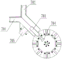
fig. 9 is a schematic structural view of the blanking device used in cooperation with the turntable in the embodiment of the present invention.
In the figure: 1. a first vibrating feeding tray; 2. a second vibration feeding tray; 3. an extrusion device; 4. a turntable; 5. A detection device; 6. a cylinder support; 7. a blanking device; 8. a positioning groove body;
101. a carriage; 102. a first straight material channel; 103. a first cylinder; 104. a fourth pushing head; 105. a discharge port; 106. a feeding seat; 107. a second cylinder;
201. a second straight material channel; 202. a vibration bracket; 203. a vibrator; 204. a support plate; 205. a support table; 206. a third cylinder; 207. a slide rail; 208. a fourth cylinder; 209. a fifth cylinder; 210. A second pushing head; 211. a groove; 212. a chute.
301. A first support frame; 302. a column; 303. a sixth cylinder; 304. pipe sleeve; 305. a third pushing head; 401. a probe; 402. a seventh cylinder; 403. a second support frame;
701. a first blanking channel; 702. a second blanking channel; 703. an eighth cylinder; 704. a first pushing head; 705. and a ninth cylinder.
Detailed Description
It should be noted that the following detailed description is exemplary and is intended to provide further explanation of the disclosure. Unless defined otherwise, all technical and scientific terms used herein have the same meaning as commonly understood by one of ordinary skill in the art to which this application belongs.
It is noted that the terminology used herein is for the purpose of describing particular embodiments only and is not intended to be limiting of example embodiments according to the present application. As used herein, the singular forms "a", "an" and "the" are intended to include the plural forms as well, and it should be understood that when the terms "comprises" and/or "comprising" are used in this specification, they specify the presence of stated features, steps, operations, devices, components, and/or combinations thereof, unless the context clearly indicates otherwise.
The utility model discloses an among the typical embodiment, as 1-9 shows, a sealing washer automatic assembly device for brake alarm plug, including controlling means and can follow self axis pivoted carousel 4, carousel 4 sets up in the upper surface of workstation, the upper surface of carousel 4 is equipped with a plurality of location cell bodies 8 along the circumferencial direction equipartition, location cell body 8 is used for realizing the location of work piece on carousel 4.
The outer side of the rotary table 4 is sequentially provided with a first vibration feeding disc 1, a second vibration feeding disc 2, an extruding device 3, a detecting device 5 and a discharging device 7 along a set rotary direction.
The plug is stored in the first vibration feeding tray 1, the plug can be conveyed to the first feeding device through the first vibration feeding tray 1 according to a set posture, and the workpiece can be conveyed to the adjacent positioning groove bodies 8 through the first feeding device.
The sealing ring is stored in the second vibration feeding disc 2, the second vibration feeding disc 2 can convey the sealing ring to a second feeding device according to a set posture, and the second feeding device can convey the sealing ring to the upper part of the adjacent plug and realize the primary positioning of the plug and the sealing ring.
The lower end of the extruding device 3 can move up and down under the driving of the driving device so as to extrude the sealing ring and realize the pressing of the sealing ring and the plug.
The detection device 5 comprises a vertically arranged probe 401, the probe 401 can move up and down to be inserted into the positioning groove body 8, and the pressing depth of the sealing ring and the workpiece is detected.
The control device can control the turntable 4 to rotate for a set angle and read a signal of the probe 401, and judge whether the pressing of the sealing ring and the workpiece meets the requirement.
The blanking device 7 can enable the first blanking channel 701 or the second blanking channel 702 to be aligned to a blanking port according to a signal of the control device, a blanking cylinder is arranged at the position of the blanking port, a first push head 704 is arranged at a piston rod of the blanking cylinder, and the first push head 704 pushes out a pressed workpiece and a pressed sealing ring from the positioning groove body 8.
The first feeding device, the second feeding device, the extruding device 3, the detecting device 5 and the blanking device 7 are sequentially arranged around the turntable 4 along the set rotating direction.
Further, the first straight channel 102 of the first vibrating feeding tray 1 is communicated with a first feeding device.
And a second straight channel 201 of the second vibrating feeding tray 2 is communicated with a second feeding device.
Further, a rotating shaft is arranged in the middle of the rotating disc 4 and fixedly connected with an output shaft of the driving motor, and the output shaft of the driving motor is vertically and upwards arranged.
Further, the first feeding device comprises a second air cylinder 107 fixed with the workbench, an output shaft of the second air cylinder 107 is vertically arranged upwards, a feeding seat 106 is arranged at the upper end of a piston rod in the second air cylinder 107, and a clamping groove is formed in the feeding seat 106 and used for accommodating a plug fed from the first straight material channel 102.
The upper end of the second cylinder 107 is fixedly connected with a carriage 101, the feeding seat 106 can lift along the inner cavity of the carriage 101, the top end of the carriage 101 is provided with a discharge hole 105, the upper end of the carriage 101 is fixedly provided with a first cylinder 103, the shell of the first cylinder 103 is fixedly connected with the carriage 101, the tail end of the piston rod of the first cylinder 103 is fixedly connected with a fourth push head 104, and the fourth push head 104 is arranged opposite to the discharge hole 105.
Further, a vibrator 203 is arranged below the second straight material channel 201, and the vibrator 203 is fixedly connected with the lower surface of the second straight material channel 201 through a vibration bracket 202.
Further, the second feeding device comprises a supporting plate 204 fixed with the workbench, a supporting table 205 is arranged above the supporting plate 204, a groove is formed in the upper surface of the supporting table 205, the groove is communicated with the second straight material channel 201, a sliding groove is formed in the upper surface of the supporting table 205, the sliding groove is perpendicular to the groove, a clamping plate is arranged in the sliding groove, the clamping plate can push out a sealing ring in the groove under the driving of a third air cylinder 206 and send the sealing ring to the lower portion of a second pushing head 210, the second pushing head 210 is fixed to the tail end of a piston rod of a fourth air cylinder 208, and the piston rod of the fourth air cylinder 208 is vertically arranged.
Specifically, the housing of the fourth cylinder is fixed to a sliding block, the sliding block is disposed in a sliding rail 207 which is horizontally arranged, the extending direction of the sliding rail is the same as the extending direction of the fifth cylinder, and the sliding rail is used for bearing the gravity of the fourth cylinder.
The second pushing head 210 can be engaged with the sealing ring during the process of descending.
The shell of the fourth cylinder 208 is fixed with the piston rod of the fifth cylinder 209, the shell of the fifth cylinder 209 is fixed with the support plate 204, and the piston rod in the fifth cylinder 209 can convey the sealing ring below the second push head 210 to the upper part of the plug to be assembled.
Further, the extrusion device 3 comprises a vertical column 302 fixedly connected with the upper surface of the workbench, a first support frame 301 is fixedly arranged above the vertical column 302, a sixth air cylinder 303 with a piston rod vertically arranged downwards is arranged in the first support frame 301, and the tail end of the piston rod of the sixth air cylinder 303 is fixed with a third push head 305.
Specifically, the first support bracket is fixed to a pipe sleeve 304 through which a piston rod of the sixth cylinder passes.
Further, the third pushing head 305 is cylindrical, and an inner cavity of the third pushing head 305 is used for inserting a fixing column of a plug.
Further, the detection device 5 includes a second upright column 302 fixedly connected to the upper surface of the workbench, a second support frame 403 is fixedly disposed above the second upright column 302, a seventh cylinder 402 with a piston rod disposed vertically downward is disposed in the second support frame, the piston rod of the seventh cylinder 402 is fixedly connected to the probe 401, and the probe 401 is disposed vertically downward.
Specifically, the lower extreme of probe is equipped with infrared emitter and infrared receiver, measures the distance of probe lower extreme and sealing washer through infrared range finding mode, and then judges whether the pressfitting of sealing washer is qualified.
In other embodiments, a pressure sensor is arranged between the top end of the probe and the piston rod of the seventh cylinder, and after the probe is lowered to the set position, if the value of the pressure sensor is greater than a set value, it indicates that the sealing ring is not lowered to the set position; if the value of the pressure sensor is smaller than the set value, the sealing ring is lowered to the set position.
Further, an eighth air cylinder 703 is arranged on one side of the workbench, the first push head 704 is arranged at the tail end of a piston rod of the eighth air cylinder 703, and the first push head 704 is used for pushing out the plug detected by the detection device 5 from the positioning groove body 8.
A blanking channel is arranged on one side of the outer side of the turntable 4 and comprises a first blanking channel 701 and a second blanking channel 702 which are fixedly connected, the bottom ends of the first blanking channel and the second blanking channel are fixedly connected with a piston rod of a ninth cylinder 705, the cylinder body of the ninth cylinder 705 is fixedly connected with a workbench, and the piston rod of the ninth cylinder 705 can stretch out and draw back to enable the first blanking channel 701 or the second blanking channel 702 to respectively align to the positioning groove body 8 at the position of the first push head 704.
The working principle is as follows:
when the device is used, the plug is placed into the inner cavity of the first vibration feeding disc, and the sealing ring is placed into the inner cavity of the second vibration feeding disc. The first vibration feeding tray vibrates and feeds the plug to the first feeding device according to a set posture, a first straight material channel 102 of the first vibration feeding tray is aligned with a clamping groove in a feeding seat 106, the plug enters the clamping groove, then a piston rod of a second air cylinder 107 rises to drive the feeding seat 106 to rise, so that the clamping groove is aligned with a discharging hole 105, then the piston rod of a first air cylinder 103 extends out, and a fourth pushing head 104 pushes the plug into a positioning groove body 8; the rotating disc 4 rotates and moves the positioning groove body 8 with the plug to a station corresponding to the second feeding device.
The second straight material channel 201 of the second vibration feeding tray feeds the sealing ring to the second feeding device according to a set posture, the second straight material channel 201 of the second vibration feeding tray is aligned with the groove, the sealing ring is fed into the groove, and then the third air cylinder 206 pushes one sealing ring to the sliding groove by using the clamping plate, so that the sealing ring is positioned below the second pushing head 210.
The fourth cylinder 208 descends to enable the second push head 210 to be clamped into the sealing ring for a part of distance, then the fourth cylinder 208 is lifted, the fifth cylinder 209 pushes the second push head to the upper side of the plug of the station where the second cylinder 208 is located, the fourth cylinder 208 descends to enable the sealing ring to be in contact with the plug, the cylinder in the middle of the plug is completely inserted into the sealing ring, then the fourth cylinder 208 ascends, the friction force between the second push head 210 and the sealing ring is smaller than the friction force between the cylinder in the middle of the plug and the sealing ring, the second push head 210 is separated from the sealing ring, and the second push head 210 resets.
The rotating disc 4 rotates to enable the positioning groove body 8 provided with the plug and the sealing ring to move to the lower part of the extrusion device 3, the piston rod of the sixth air cylinder 303 in the extrusion device 3 descends, the third push head 305 is in contact with the sealing ring and pushes the sealing ring into the inner cavity of the plug completely, and the third push head 305 is of an annular structure.
The turntable 4 continues to rotate, so that the positioning groove body 8 provided with the plug and the sealing ring moves to the position below the detection device 5, the probe 401 descends, and the probe 401 detects the depth of the sealing ring extruded into the plug and transmits the depth information to the control device;
the turntable 4 continues to rotate so that the positioning groove body 8 provided with the plug and the sealing ring moves to the blanking device 7, the control device judges whether the extrusion depth of the sealing ring is qualified or not according to the depth information of the detection device 5, if the extrusion depth is unqualified, a first blanking channel 701 is adopted for blanking, and if the extrusion depth is qualified, a second blanking channel 702 is adopted for blanking; the ninth cylinder 705 enables the first blanking channel 701 or the second blanking channel 702 to be aligned with the corresponding positioning groove body 8, and the eighth cylinder 703 drives the first push head 704 to push the plug out of the positioning groove body 8 to achieve blanking.
Although the present invention has been described with reference to the accompanying drawings, it is not intended to limit the scope of the present invention, and those skilled in the art should understand that various modifications or variations that can be made by those skilled in the art without inventive work are still within the scope of the present invention.
Claims (10)
1. The automatic assembling device for the sealing ring for the brake alarm plug is characterized by comprising a control device and a rotary table capable of rotating along the axis of the rotary table, wherein the rotary table is arranged on the upper surface of a workbench, and a plurality of positioning groove bodies are uniformly distributed on the upper surface of the rotary table in the circumferential direction;
a first vibration feeding disc, a second vibration feeding disc, an extrusion device, a detection device and a discharging device are sequentially arranged on the outer side of the rotary disc along a set rotary direction;
the first vibration feeding disc can convey the plugs stored in the first vibration feeding disc to a first feeding device according to a set posture, and the first feeding device can convey the plugs to adjacent positioning groove bodies;
the second vibration feeding disc can convey the sealing rings stored in the second vibration feeding disc to a second feeding device according to a set posture, and the second feeding device can convey the sealing rings to the positions above the adjacent plugs and realize the primary positioning of the plugs and the sealing rings;
the lower end of the extrusion device can move up and down to extrude the sealing ring into the plug completely;
the detection device can detect the pressing depth of the sealing ring and the plug;
the blanking device comprises a blanking cylinder fixedly arranged with the workbench, a first push head is arranged at a piston rod of the blanking cylinder, and the first push head can push out the plug and the sealing ring detected by the detection device from the positioning groove body;
the control device can control the rotary disc to rotate and judge whether the assembly of the plug and the sealing ring is qualified or not according to the signal of the detection device.
2. The automatic assembling device for the sealing ring for the brake alarm plug according to claim 1, wherein a first straight material channel of the first vibrating feeding disc is communicated with a first feeding device; and a second straight material channel of the second vibration feeding disc is communicated with a second feeding device.
3. The automatic assembling device for the sealing ring for the brake alarm plug according to claim 1, wherein a rotating shaft is arranged in the middle of the rotating disc, the rotating shaft is fixedly connected with an output shaft of a driving motor, and the output shaft of the driving motor is vertically and upwardly arranged.
4. The automatic assembling device for the sealing ring for the brake alarm plug according to claim 1, wherein the first feeding device comprises a second air cylinder fixed with a workbench, an output shaft of the second air cylinder is vertically and upwardly arranged, a feeding seat is arranged at the upper end of a piston rod in the second air cylinder, and a clamping groove is formed in the feeding seat and used for accommodating the plug fed from the first straight material channel;
the upper end fixedly connected with balladeur train of second cylinder, the inner chamber lift of balladeur train can be followed to the pay-off seat, the top of balladeur train is equipped with the discharge gate, the upper end of balladeur train is fixed and is equipped with first cylinder, the shell and the balladeur train fixed connection of first cylinder, the piston rod end and the fourth of first cylinder push away first fixed connection, the fourth is pushed away the head and is just being set up to the discharge gate.
5. The automatic assembling device for the sealing ring for the brake alarm plug according to claim 2, wherein a vibrator is arranged below the second straight material channel, and the vibrator is fixedly connected with the lower surface of the second straight material channel through a vibration support.
6. The automatic assembling device for the sealing ring for the brake alarm plug according to claim 1, wherein the second feeding device comprises a supporting plate fixed with a workbench, a supporting table is arranged above the supporting plate, a groove is formed in the upper surface of the supporting table and communicated with a second straight material channel, a sliding groove is formed in the upper surface of the supporting table and perpendicular to the groove, a clamping plate is arranged in the sliding groove and can push out the sealing ring in the groove under the driving of a third air cylinder and send the sealing ring to the lower side of a second pushing head, the second pushing head is fixed with the tail end of a piston rod of a fourth air cylinder, and the piston rod of the fourth air cylinder is vertically arranged;
the second push head can be clamped and positioned with the sealing ring in the descending process;
the shell of the fourth cylinder is fixed with the piston rod of the fifth cylinder, the shell of the fifth cylinder is fixed with the supporting plate, and the piston rod in the fifth cylinder can convey the sealing ring below the second push head to the position above the plug to be assembled.
7. The automatic assembling device for the seal ring for the brake alarm plug according to claim 1, wherein the extruding device comprises a stand column fixedly connected with the upper surface of the workbench, a first support frame is fixedly arranged above the stand column, a sixth air cylinder with a piston rod vertically and downwardly arranged is arranged in the first support frame, and the tail end of the piston rod of the sixth air cylinder is fixed with a third pushing head.
8. The automatic assembling device for the seal ring for the brake alarm plug according to claim 7, wherein the third pushing head is cylindrical, and an inner cavity of the third pushing head is used for inserting a fixing column of the plug.
9. The automatic assembling device for the seal ring for the brake alarm plug according to claim 1, wherein the detection device comprises a second upright column fixedly connected with the upper surface of the workbench, a second support frame is fixedly arranged above the second upright column, a seventh cylinder with a piston rod vertically arranged downwards is arranged in the second support frame, the piston rod of the seventh cylinder is fixedly connected with the probe, and the probe is vertically arranged downwards.
10. The automatic assembling device for the sealing ring for the brake alarm plug according to claim 1, wherein an eighth cylinder is arranged on one side of the workbench, the first push head is arranged at the tail end of a piston rod of the eighth cylinder, and the first push head is used for pushing the plug detected by the detection device out of the positioning groove body;
the utility model discloses a positioning groove body, including carousel, first unloading passageway, piston rod and workstation, the outside one side of carousel is equipped with the unloading passageway, the unloading passageway includes fixed connection's first unloading passageway and second unloading passageway, the bottom of first unloading passageway and second unloading passageway and the piston rod fixed connection of ninth cylinder, the cylinder body and the workstation fixed connection of ninth cylinder, the piston rod of ninth cylinder can stretch out and draw back and make first unloading passageway or second unloading passageway aim at first positioning groove body of pushing away head department respectively.
Priority Applications (1)
| Application Number | Priority Date | Filing Date | Title |
|---|---|---|---|
| CN201921535850.6U CN210703442U (en) | 2019-09-12 | 2019-09-12 | Automatic assembling device for sealing ring for plug of brake alarm |
Applications Claiming Priority (1)
| Application Number | Priority Date | Filing Date | Title |
|---|---|---|---|
| CN201921535850.6U CN210703442U (en) | 2019-09-12 | 2019-09-12 | Automatic assembling device for sealing ring for plug of brake alarm |
Publications (1)
| Publication Number | Publication Date |
|---|---|
| CN210703442U true CN210703442U (en) | 2020-06-09 |
Family
ID=70957094
Family Applications (1)
| Application Number | Title | Priority Date | Filing Date |
|---|---|---|---|
| CN201921535850.6U Active CN210703442U (en) | 2019-09-12 | 2019-09-12 | Automatic assembling device for sealing ring for plug of brake alarm |
Country Status (1)
| Country | Link |
|---|---|
| CN (1) | CN210703442U (en) |
Cited By (2)
| Publication number | Priority date | Publication date | Assignee | Title |
|---|---|---|---|---|
| CN112059604A (en) * | 2020-09-14 | 2020-12-11 | 靳红艳 | A carousel formula intelligence rigging equipment that is used for tap to fall spiral shell O type circle |
| CN112059940A (en) * | 2020-08-27 | 2020-12-11 | 苏州瑞康真空科技有限公司 | Tensile member goes into carousel supplied materials and has or not detection mechanism |
-
2019
- 2019-09-12 CN CN201921535850.6U patent/CN210703442U/en active Active
Cited By (2)
| Publication number | Priority date | Publication date | Assignee | Title |
|---|---|---|---|---|
| CN112059940A (en) * | 2020-08-27 | 2020-12-11 | 苏州瑞康真空科技有限公司 | Tensile member goes into carousel supplied materials and has or not detection mechanism |
| CN112059604A (en) * | 2020-09-14 | 2020-12-11 | 靳红艳 | A carousel formula intelligence rigging equipment that is used for tap to fall spiral shell O type circle |
Similar Documents
| Publication | Publication Date | Title |
|---|---|---|
| CN107470890B (en) | Pump body bent axle spring on-line installation equipment | |
| CN108213928B (en) | Clamp spring mounting device of electronic water pump | |
| CN210703442U (en) | Automatic assembling device for sealing ring for plug of brake alarm | |
| CN215237084U (en) | Limiting plate stamping device | |
| CN109093390B (en) | Motor upper cover adjusting bolt crimping frock | |
| CN110165816B (en) | Motor O-shaped ring, wave washer and rotor assembly equipment | |
| CN111251749A (en) | Ball-point pen spring pen point assembling device | |
| CN112091600A (en) | Full-automatic workpiece bushing and pin press-in device | |
| CN113146236B (en) | Press-fitting system and method for mounting seat ring and guide pipe on cylinder cover | |
| CN113162337B (en) | Automatic loop wire of submersible motor | |
| CN108512013B (en) | Automatic assembly equipment for torsion spring jacks of connectors of new energy automobiles | |
| CN212496412U (en) | Full-automatic workpiece bushing and pin press-in device | |
| CN109066266B (en) | Full-automatic equipment plug equipment | |
| CN213034028U (en) | Automatic bottom pressing machine | |
| CN110666412B (en) | Full-automatic welding machine and production method | |
| CN217991543U (en) | Automatic change quick change mechanism | |
| CN111341952A (en) | Battery cap assembling machine | |
| CN213969834U (en) | Bearing assembling equipment for heat radiation fan | |
| CN114178811A (en) | Automatic assembling equipment for air conditioner pipeline filter | |
| CN211277263U (en) | Assembly device for temperature controller adjusting part | |
| CN211589138U (en) | Ball unloading subassembly of linear bearing automatic installation equipment | |
| CN110871246B (en) | I-shaped button kludge | |
| CN217254340U (en) | Sealing washer automatic feeding assembly device of cylindric part | |
| CN216126140U (en) | Airtight detection mechanism and system thereof | |
| CN215699609U (en) | Valve block assembly quality |
Legal Events
| Date | Code | Title | Description |
|---|---|---|---|
| GR01 | Patent grant | ||
| GR01 | Patent grant |