CN210701947U - Pole piece punching device for lithium battery production - Google Patents
Pole piece punching device for lithium battery production Download PDFInfo
- Publication number
- CN210701947U CN210701947U CN201921116004.0U CN201921116004U CN210701947U CN 210701947 U CN210701947 U CN 210701947U CN 201921116004 U CN201921116004 U CN 201921116004U CN 210701947 U CN210701947 U CN 210701947U
- Authority
- CN
- China
- Prior art keywords
- lead screw
- punching
- platform
- mounting plate
- discharging platform
- Prior art date
- Legal status (The legal status is an assumption and is not a legal conclusion. Google has not performed a legal analysis and makes no representation as to the accuracy of the status listed.)
- Active
Links
Images


Landscapes
- Battery Electrode And Active Subsutance (AREA)
Abstract
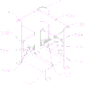
The utility model discloses a die-cut device of pole piece for lithium cell production, including support, blowing platform, ejection of compact platform, die-cut platform and hydraulic press, one side of blowing platform is provided with die-cut platform, the opposite side of die-cut platform is provided with the ejection of compact platform, blowing platform and ejection of compact platform bottom welding have eight the support, blowing platform and ejection of compact platform bottom have conveyor by the bolt fastening, conveyor includes mounting panel, first gag lever post, first lead screw, movable block and motor, the mounting panel is fixed respectively in blowing platform and ejection of compact platform bottom surface, be provided with one between the mounting panel first lead screw, the movable block is installed on the first lead screw, on be provided with two first gag lever posts around the first lead screw, mounting panel one side is provided with the motor, die-cut bench side is provided with die-cut device. Has the advantages that: the position of the cutter can be adjusted, so that various pole pieces can be punched, the conveying process cannot deviate, and the quality of the pole pieces is high.
Description
Technical Field
The utility model relates to a die-cut device technical field specifically is die-cut device of pole piece for lithium cell production.
Background
The lithium battery is a battery which uses lithium metal or lithium alloy as a negative electrode material and uses a non-aqueous electrolyte solution, and the punching of the pole piece for the production of the lithium battery is a procedure for cutting the large positive and negative pole pieces into small pieces so as to adapt to the production of lithium battery laminations. Most of the existing pole piece punching devices for lithium battery production are fixed by cutters, the punched pole pieces are single in variety, and the pole pieces can deviate in the conveying process, so that the punching quality is unqualified.
SUMMERY OF THE UTILITY MODEL
The utility model provides a technical scheme can effectively solve the die-cut device of pole piece for lithium cell production that proposes in the above-mentioned background art and be the cutter mostly fixed, and the pole piece variety of die-cut is single, and the pole piece is the deviation can appear in transportation process, leads to die-cut unqualified problem of quality to appear.
In order to achieve the above object, the utility model provides a following technical scheme:
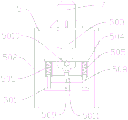
the pole piece punching device for lithium battery production comprises a support, a discharging table, eight discharging tables, a punching table and a hydraulic machine, wherein the punching table is arranged on one side of the discharging table, the discharging table is arranged on the other side of the punching table, the eight supports are welded on the discharging table and the bottom of the discharging table, two conveying devices are fixed on the discharging table and the bottom of the discharging table through bolts, each conveying device comprises a mounting plate, a first limiting rod, a first lead screw, a movable block and a motor, the mounting plates are respectively fixed on the discharging table and the bottom surface of the discharging table, one first lead screw is arranged between the mounting plates, the movable block is mounted on the first lead screw, two first limiting rods are arranged on the front and back of the first lead screw, the motor is arranged on one side of the mounting plate, and the punching device is arranged above the punching table, the punching device comprises a pressing plate, a punching support, a hydraulic rod, a punching mounting plate, a spring, a second limiting rod, a second lead screw, a third movable rod, a cutter, an adjusting knob and a cutter mounting plate, wherein the punching support is fixed on the support, the hydraulic machine is arranged at the top of the punching support, the hydraulic rod is connected below the hydraulic machine, the punching mounting plate is fixed at the lower end of the hydraulic machine through bolts, the second lead screw is arranged below the punching mounting plate, the cutter mounting plate is arranged on the second lead screw, two second limiting rods are arranged around the second lead screw, one side of the second lead screw is connected with the adjusting knob, four third movable rods are arranged below the punching mounting plate, the spring is arranged between the third movable rods and the punching mounting plate, and the lower ends of the third movable rods are welded with the pressing plate, the cutter is installed on the cutter installation plate through a bolt.
Preferably, the discharging platform and the discharging platform are identical in structure, the discharging platform and the discharging platform are both concave platforms, and two rectangular grooves are formed in the bottoms of the concave platforms.
Preferably, the second lead screw penetrates through the cutter mounting plate, and threads meshed with the second lead screw are formed in the cutter mounting plate.
Preferably, the movable block is provided with two trapezoidal bulges.
Preferably, the first lead screw penetrates through the movable block, and a thread meshed with the first lead screw is formed in the movable block.
Compared with the prior art, the beneficial effects of the utility model are that: the utility model has the advantages of being scientific and reasonable in structure, convenience safe in utilization:
1. the feeding table and the discharging table are concave tables, and baffles are arranged on two sides of the concave tables, so that the deviation in the pole piece conveying process can be avoided by matching with a conveying device, and the quality of the punched pole piece is ensured;
2. the pressing plate is arranged, so that the stress of the pole piece is kept flat, and the punching quality of the pole piece is ensured;
3. set up adjust knob and second lead screw for die-cut cutter can carry out the accurate adjustment, can accomplish the die-cut of multiple pole piece.
Drawings
Fig. 1 is a schematic perspective view of the present invention;
fig. 2 is a front view of the present invention;
fig. 3 is a schematic perspective view of the punching device of the present invention;
fig. 4 is a schematic structural view of the punching device of the present invention;
fig. 5 is a schematic structural view of the stamping mounting plate of the present invention;
fig. 6 is a schematic structural view of the conveying device of the present invention.
Reference numbers in the figures: 1. a support; 2. a discharge table; 3. a discharging table; 4. a conveying device; 401. mounting a plate; 402. a first limit rod; 403. a first lead screw; 404. a movable block; 405. a motor; 5. a punching device; 501. pressing a plate; 502 die cutting the support; 503. a hydraulic lever; 504. stamping the mounting plate; 505. a spring; 506. a second limiting rod; 507. a second lead screw; 508. a third movable bar; 509. a cutter; 5010. adjusting a knob; 5011. a cutter mounting plate; 6. a punching table; 7. and (4) a hydraulic press.
Detailed Description
The technical solutions in the embodiments of the present invention will be described clearly and completely with reference to the accompanying drawings in the embodiments of the present invention, and it is obvious that the described embodiments are only some embodiments of the present invention, not all embodiments. Based on the embodiments in the present invention, all other embodiments obtained by a person skilled in the art without creative work belong to the protection scope of the present invention.
Example (b): as shown in FIGS. 1-6, the utility model provides a technical solution, a pole piece punching device for lithium battery production, comprising a support 1, a discharging platform 2, a discharging platform 3, a punching platform 6 and a hydraulic machine 7, wherein one side of the discharging platform 2 is provided with the punching platform 6, the other side of the punching platform 6 is provided with the discharging platform 3, eight supports 1 are welded at the bottoms of the discharging platform 2 and the discharging platform 3, the discharging platform 2 and the discharging platform 3 have the same structure, both the discharging platform 2 and the discharging platform 3 are concave platforms, which ensures that no offset occurs in the pole piece conveying process, two conveying devices 4 are fixed at the bottoms of the discharging platform 2 and the discharging platform 3 by bolts, each conveying device 4 comprises a mounting plate 401, a first limiting rod 402, a first lead screw 403, a movable block 404 and a motor 405, the mounting plates 401 are respectively fixed at the bottom surfaces of the discharging platform 2 and the discharging platform 3, a first lead screw 403 is arranged between the mounting plates 401, the movable block 404 is mounted on, two first limiting rods 402 are arranged at the front and the back of a first lead screw 403, the first limiting rods 402 ensure that a movable block 404 does not deviate in the moving process, a motor 405 is arranged at one side of a mounting plate 401, a punching device 5 is arranged above a punching table 6, the punching device 5 comprises a pressing plate 501, a punching support 502, a hydraulic rod 503, a punching mounting plate 504, a spring 505, a second limiting rod 506, a second lead screw 507, a third movable rod 508, a cutter 509, an adjusting knob 5010 and a cutter mounting plate 5011, the punching support 502 is fixed on the support 1, a hydraulic machine 7 is arranged at the top of the punching support 502, the hydraulic rod 503 is connected below the hydraulic machine 7, the punching mounting plate 504 is fixed at the lower end of the hydraulic machine 7 through a bolt, a second lead screw 507 is arranged below the punching mounting plate 504, the cutter mounting plate 5011 is arranged on the second lead screw 507, in order to ensure that the cutter 509 does, one side of the second lead screw 507 is connected with an adjusting knob 5010, four third movable rods 508 are arranged below the stamping mounting plate 504, springs 505 are arranged between the third movable rods 508 and the stamping mounting plate 504, a pressing plate 501 is welded at the lower end of each third movable rod 508, the pressing plate 501 enables the pole pieces to be flat and smooth, the punching quality is high, and the cutter 509 is mounted on the cutter mounting plate 5011 through bolts.
Preferably, the second lead screw 507 penetrates through the cutter mounting plate 5011, and threads meshed with the second lead screw 507 are formed in the cutter mounting plate 5011; two trapezoidal bulges are arranged on the movable block 404; the first lead screw 403 penetrates the movable block 404, and a thread engaged with the first lead screw 403 is formed in the movable block 404.
The utility model discloses a theory of operation and use flow: the lithium battery pole piece is placed into the discharging table 2 and transported to the punching table 6 through the conveying device 4, the hydraulic machine 7 works to push the hydraulic rod 503 to move downwards, the punching mounting plate 504 below the hydraulic rod 503 moves downwards, the cutter 509 mounted on the cutter mounting plate 5011 also punches the pole piece pressed by the pressing plate 501 downwards, the punching device 5 retracts after punching is completed, the pole piece is transported to the discharging table 3 through the conveying device 4 and taken out, and other pole pieces can be punched by changing the position of the cutter 509 through adjusting the adjusting knob 5010.
It is noted that, herein, relational terms such as first and second, and the like may be used solely to distinguish one entity or action from another entity or action without necessarily requiring or implying any actual such relationship or order between such entities or actions. Also, the terms "comprises," "comprising," or any other variation thereof, are intended to cover a non-exclusive inclusion, such that a process, method, article, or apparatus that comprises a list of elements does not include only those elements but may include other elements not expressly listed or inherent to such process, method, article, or apparatus.
Finally, it should be noted that: although the present invention has been described in detail with reference to the foregoing embodiments, it will be apparent to those skilled in the art that modifications may be made to the embodiments described in the foregoing embodiments, or equivalents may be substituted for elements thereof. Any modification, equivalent replacement, or improvement made within the spirit and principle of the present invention should be included in the protection scope of the present invention.
Claims (5)
1. Die-cut device of pole piece for lithium cell production, including support (1), blowing platform (2), play work or material rest (3), die-cut platform (6) and hydraulic press (7), its characterized in that: one side of the discharging platform (2) is provided with the punching platform (6), the other side of the punching platform (6) is provided with the discharging platform (3), the discharging platform (2) and the bottom of the discharging platform (3) are welded with eight brackets (1), the discharging platform (2) and the bottom of the discharging platform (3) are fixed with two conveying devices (4) through bolts, each conveying device (4) comprises a mounting plate (401), a first limiting rod (402), a first lead screw (403), a movable block (404) and a motor (405), the mounting plates (401) are respectively fixed on the bottom surfaces of the discharging platform (2) and the discharging platform (3), one first lead screw (403) is arranged between the mounting plates (401), the movable block (404) is mounted on the first lead screw (403), and the first limiting rods (402) are arranged around the first lead screw (403), the motor (405) is arranged on one side of the mounting plate (401), the punching device (5) is arranged above the punching table (6), the punching device (5) comprises a pressing plate (501), a punching support (502), a hydraulic rod (503), a punching mounting plate (504), a spring (505), a second limiting rod (506), a second lead screw (507), a third movable rod (508), a cutter (509), an adjusting knob (5010) and a cutter mounting plate (5011), the punching support (502) is fixed on the support (1), the hydraulic machine (7) is arranged on the top of the punching support (502), the hydraulic rod (503) is connected below the hydraulic machine (7), the punching mounting plate (504) is fixed on the lower end of the hydraulic machine (7) through bolts, the second lead screw (507) is arranged below the punching mounting plate (504), and the cutter mounting plate (5011) is arranged on the second lead screw (507), be provided with two around second lead screw (507) second gag lever post (506), one side of second lead screw (507) is connected with adjust knob (5010), punching press mounting panel (504) below is provided with four third movable rod (508), third movable rod (508) with install between punching press mounting panel (504) spring (505), third movable rod (508) lower extreme welding clamp plate (501), cutter (509) are installed through the bolt on cutter mounting panel (5011).
2. The pole piece punching device for lithium battery production of claim 1, characterized in that: the discharging platform (2) and the discharging platform (3) are identical in structure, the discharging platform (2) and the discharging platform (3) are concave platforms, and two rectangular grooves are formed in the bottoms of the concave platforms.
3. The pole piece punching device for lithium battery production of claim 1, characterized in that: the second lead screw (507) penetrates through the cutter mounting plate (5011), and threads meshed with the second lead screw (507) are formed in the cutter mounting plate (5011).
4. The pole piece punching device for lithium battery production of claim 1, characterized in that: two trapezoidal bulges are arranged on the movable block (404).
5. The pole piece punching device for lithium battery production of claim 1, characterized in that: the first lead screw (403) penetrates through the movable block (404), and a thread meshed with the first lead screw (403) is formed in the movable block (404).
Priority Applications (1)
| Application Number | Priority Date | Filing Date | Title |
|---|---|---|---|
| CN201921116004.0U CN210701947U (en) | 2019-07-17 | 2019-07-17 | Pole piece punching device for lithium battery production |
Applications Claiming Priority (1)
| Application Number | Priority Date | Filing Date | Title |
|---|---|---|---|
| CN201921116004.0U CN210701947U (en) | 2019-07-17 | 2019-07-17 | Pole piece punching device for lithium battery production |
Publications (1)
| Publication Number | Publication Date |
|---|---|
| CN210701947U true CN210701947U (en) | 2020-06-09 |
Family
ID=70964393
Family Applications (1)
| Application Number | Title | Priority Date | Filing Date |
|---|---|---|---|
| CN201921116004.0U Active CN210701947U (en) | 2019-07-17 | 2019-07-17 | Pole piece punching device for lithium battery production |
Country Status (1)
| Country | Link |
|---|---|
| CN (1) | CN210701947U (en) |
Cited By (1)
| Publication number | Priority date | Publication date | Assignee | Title |
|---|---|---|---|---|
| CN112670586A (en) * | 2020-12-21 | 2021-04-16 | 湖南久森新能源有限公司 | Pelleter for lithium battery production and fixing structure thereof |
-
2019
- 2019-07-17 CN CN201921116004.0U patent/CN210701947U/en active Active
Cited By (1)
| Publication number | Priority date | Publication date | Assignee | Title |
|---|---|---|---|---|
| CN112670586A (en) * | 2020-12-21 | 2021-04-16 | 湖南久森新能源有限公司 | Pelleter for lithium battery production and fixing structure thereof |
Similar Documents
| Publication | Publication Date | Title |
|---|---|---|
| TWM524230U (en) | Pole ear cutting machine | |
| CN210701947U (en) | Pole piece punching device for lithium battery production | |
| CN215508500U (en) | Stamping device with panel beating location structure | |
| CN113001188A (en) | Efficient tank shell plate shearing and punching integrated equipment with waste recycling function and using method thereof | |
| CN210147091U (en) | Edge cutting device with fixing mechanism for lithium battery production | |
| CN210059521U (en) | Stamping die structure is sent in same direction as to banded sheet material of metal | |
| CN215143818U (en) | Two-device fin machining die device | |
| CN214078751U (en) | Battery tab positioning and punching device | |
| CN209786072U (en) | Metal sodium electrode wafer manufacturing device | |
| CN213378751U (en) | Porous punching press of leaf spring clamp is expected device absolutely | |
| CN211464346U (en) | Multi-piece stacked annealing or shaping jig | |
| CN211437693U (en) | Quick die change punching device of transformer core horizontal trimming | |
| CN211045625U (en) | Hot-pressing die for lithium ion battery winding cell | |
| CN208787342U (en) | A kind of copper bar processing mold | |
| CN217990660U (en) | High-precision stamping die for metal plate processing | |
| CN218568881U (en) | Die cutting device for double-sheet discharge of battery cell pole piece | |
| CN209658326U (en) | The power tab angle apparatus of falling R automatically | |
| CN211465290U (en) | G-shaped beam welding positioning tool | |
| CN214023583U (en) | Perforating device is used in production of porous frame of stainless steel | |
| CN207303218U (en) | A kind of versatility wrap plate screen ear punching device | |
| CN116689602A (en) | Stamping and cutting die for battery pole piece production | |
| CN211334679U (en) | Die device for button cell positive electrode shell | |
| CN213134682U (en) | Punching device for aluminum furniture | |
| CN211938632U (en) | Automobile chassis rear arm upper inner side arm die | |
| CN214981544U (en) | Continuous punching device for battery insulation sheet |
Legal Events
| Date | Code | Title | Description |
|---|---|---|---|
| GR01 | Patent grant | ||
| GR01 | Patent grant |