CN210701827U - Metal plate bending processing equipment - Google Patents
Metal plate bending processing equipment Download PDFInfo
- Publication number
- CN210701827U CN210701827U CN201920907114.2U CN201920907114U CN210701827U CN 210701827 U CN210701827 U CN 210701827U CN 201920907114 U CN201920907114 U CN 201920907114U CN 210701827 U CN210701827 U CN 210701827U
- Authority
- CN
- China
- Prior art keywords
- fixedly connected
- plate
- sheet metal
- belt pulley
- bending
- Prior art date
- Legal status (The legal status is an assumption and is not a legal conclusion. Google has not performed a legal analysis and makes no representation as to the accuracy of the status listed.)
- Active
Links
Images

Abstract
The utility model discloses a panel beating processing equipment of bending, comprising a base plate, one side fixedly connected with riser at bottom plate top to the top fixedly connected with diaphragm of riser, connecting block fixedly connected with motor is passed through to the bottom of diaphragm to the first belt pulley of one end fixedly connected with of motor output shaft, the surface of first belt pulley is connected with the second belt pulley through belt drive to the back fixedly connected with cam of second belt pulley, the axle center department of second belt pulley and cam all rotates through the bottom of fixed plate with the diaphragm and is connected. Has the advantages that: can carry out quick abundant bending in the sheet metal working process, great saving time like this has improved the efficiency of bending in the sheet metal working process, and the practicality is strong, and better assurance going on of sheet metal working is convenient for bend the panel beating steel sheet in different positions, better satisfied the demand of panel beating in the sheet metal working process of bending.
Description
Technical Field
The utility model relates to a panel beating technical field of bending particularly, relates to a panel beating processing equipment of bending.
Background
Sheet metal is also sometimes used as a gilding, and some sheet metal is generally subjected to plastic deformation by hand or die stamping to form a desired shape and size, and further can be subjected to welding or a small amount of machining to form more complicated parts, and common articles such as chimneys, sheet iron furnaces and automobile shells which are commonly used in life are sheet metal parts.
Need bend in the sheet metal working process, can't carry out quick abundant bending at the in-process of bending now, great waste time like this, reduced the efficiency of bending in the sheet metal working process, going on of unable better assurance sheet metal working, and be not convenient for bend the panel beating steel sheet in different positions, demand in the unable better satisfied panel beating process of bending.
An effective solution to the problems in the related art has not been proposed yet.
SUMMERY OF THE UTILITY MODEL
An object of the utility model is to provide a panel beating processing equipment of bending to solve the problem that proposes among the above-mentioned background art.
In order to achieve the above object, the utility model provides a following technical scheme: a sheet metal bending processing device comprises a bottom plate, wherein a vertical plate is fixedly connected with one side of the top of the bottom plate, the top of the vertical plate is fixedly connected with a transverse plate, the bottom of the transverse plate is fixedly connected with a motor through a connecting block, and one end of the output shaft of the motor is fixedly connected with a first belt pulley, the outer surface of the first belt pulley is connected with a second belt pulley through belt transmission, the back of the second belt pulley is fixedly connected with a cam, the axes of the second belt pulley and the cam are rotatably connected with the bottom of the transverse plate through a fixed plate, one side of the vertical plate is fixedly connected with a first sliding rail, and the outer surface of the first slide rail is connected with a first slide block in a sliding way, one side of the first slide block is fixedly connected with a stabilizing plate, and the top of the stabilizing plate is contacted with the outer surface of the cam, and the bottom of the stabilizing plate is fixedly connected with a bending plate through a connecting rod.
Furthermore, the top of bottom plate and the one side that is located the riser have second slide rail, backup pad and the piece of bending of fixedly connected with in proper order from a left side to the right side.
Furthermore, one side of backup pad is rotated through the bearing and is connected with the threaded rod to the one end fixedly connected with handle of backup pad is kept away from to the threaded rod, the surface threaded connection of threaded rod has the second slider, and the surface sliding connection of the bottom of second slider and second slide rail, the top fixedly connected with lower clamping plate of backup pad.
Furthermore, one side of the bottom of the transverse plate is fixedly connected with an electric telescopic rod, and the bottom end of the electric telescopic rod is fixedly connected with an upper clamping plate.
Furthermore, the top of the second sliding block is fixedly connected with a moving block, a fixed groove is formed in the moving block, the top and the bottom of the inner wall of the fixed groove are fixedly connected with first elastic pieces, and the opposite ends of the two first elastic pieces are fixedly connected with clamping blocks.
Furthermore, a second elastic piece is fixedly connected between one side of the stabilizing plate opposite to the transverse plate, and the number of the second elastic pieces is two.
Compared with the prior art, the utility model discloses following beneficial effect has:
1. the utility model discloses a drive first belt pulley through the motor and rotate, drive second belt pulley and cam rotation, the spring action through the second elastic component drives steadying plate, first slider, connecting rod and the board up-and-down motion of bending, can carry out quick abundant bending in the sheet metal working process through the board of bending and the piece of bending, great like this time of having practiced thrift, improved the efficiency of bending in the sheet metal working process, the practicality is strong, better assurance going on of sheet metal working.
2. Through the elastic action of the first elastic part in the moving block, the clamping block clamps the sheet metal plate tightly, the handle is rotated to drive the threaded rod to rotate, the second sliding block, the moving block and the sheet metal plate are driven to move, the sheet metal plate can be bent at different positions conveniently, and the requirements of the sheet metal in the bending process are better met.
Drawings
In order to more clearly illustrate the embodiments of the present invention or the technical solutions in the prior art, the drawings required to be used in the embodiments will be briefly described below, and it is obvious that the drawings in the following description are only some embodiments of the present invention, and for those skilled in the art, other drawings can be obtained according to these drawings without creative efforts.
Fig. 1 is a schematic structural diagram of a sheet metal bending device according to an embodiment of the present invention;
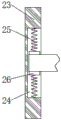
fig. 2 is a sectional view of a moving block structure of a sheet metal bending device according to the embodiment of the present invention.
Reference numerals:
1. a base plate; 2. a vertical plate; 3. a transverse plate; 4. a motor; 5. a first pulley; 6. a second pulley; 7. a cam; 8. a fixing plate; 9. a first slide rail; 10. a first slider; 11. a stabilizing plate; 12. a connecting rod; 13. bending the plate; 14. a second slide rail; 15. a support plate; 16. bending a piece; 17. a threaded rod; 18. a handle; 19. a second slider; 20. a lower clamping plate; 21. an electric telescopic rod; 22. an upper clamping plate; 23. a moving block; 24. fixing grooves; 25. a first elastic member; 26. a clamping block; 27. a second elastic member.
Detailed Description
The following, with reference to the drawings and the detailed description, further description of the present invention is made:
referring to fig. 1-2, a sheet metal bending apparatus according to an embodiment of the present invention includes a base plate 1, a vertical plate 2 is fixedly connected to one side of the top of the base plate 1, a horizontal plate 3 is fixedly connected to the top of the vertical plate 2, a motor 4 is fixedly connected to the bottom of the horizontal plate 3 through a connecting block, a first belt pulley 5 is fixedly connected to one end of an output shaft of the motor 4, a second belt pulley 6 is connected to the outer surface of the first belt pulley 5 through a belt transmission, a cam 7 is fixedly connected to the back of the second belt pulley 6, the axial centers of the second belt pulley 6 and the cam 7 are rotatably connected to the bottom of the horizontal plate 3 through a fixing plate 8, a first slide rail 9 is fixedly connected to one side of the vertical plate 2, a first slide block 10 is slidably connected to the outer surface of the first slide rail 9, and a stabilizing plate 11 is fixedly connected to one, and the top of the stabilizing plate 11 is contacted with the outer surface of the cam 7, and the bottom of the stabilizing plate 11 is fixedly connected with a bending plate 13 through a connecting rod 12.
In addition, a second slide rail 14, a support plate 15 and a bending piece 16 are fixedly connected to the top of the bottom plate 1 and one side of the vertical plate 2 from left to right in sequence, and the top of the bending piece 16 is in contact with the bottom of the sheet metal steel plate; one side of the supporting plate 15 is rotatably connected with a threaded rod 17 through a bearing, one end, far away from the supporting plate 15, of the threaded rod 17 is fixedly connected with a handle 18, the outer surface of the threaded rod 17 is in threaded connection with a second sliding block 19, the bottom of the second sliding block 19 is in sliding connection with the outer surface of the second sliding rail 14, and the top of the supporting plate 15 is fixedly connected with a lower clamping plate 20; one side of the bottom of the transverse plate 3 is fixedly connected with an electric telescopic rod 21, and the bottom end of the electric telescopic rod 21 is fixedly connected with an upper clamping plate 22; a moving block 23 is fixedly connected to the top of the second sliding block 19, a fixing groove 24 is formed in the moving block 23, first elastic pieces 25 are fixedly connected to the top and the bottom of the inner wall of the fixing groove 24, and clamping blocks 26 are fixedly connected to opposite ends of the two first elastic pieces 25; and two second elastic pieces 27 are fixedly connected between the opposite sides of the stabilizing plate 11 and the transverse plate 3, and the number of the second elastic pieces 27 is two.
Through the above scheme of the utility model, by placing the sheet metal plate into the fixing groove 24, the two clamping blocks 26 clamp the sheet metal plate tightly through the elastic action of the first elastic member 25, at this time, the sheet metal plate is just placed on the lower clamping plate 20, the handle 18 is rotated to drive the threaded rod 17 to rotate, the second slider 19, the moving block 23 and the sheet metal plate are driven to move, the sheet metal plate is adjusted to a proper position, the sheet metal plate is conveniently bent at different positions, the electric telescopic handle 21 is made to work, the electric telescopic handle 21 is extended to drive the upper clamping plate 22 to move downwards and clamp the sheet metal plate tightly through the lower clamping plate 20, then the motor 4 is made to work, the motor 4 drives the first belt pulley 5 to rotate, the second belt pulley 6 and the cam 7 to rotate, the stabilizing plate 11, the first slider 10, the connecting rod 12 and the bending plate 13 are driven to reciprocate up and down through the elastic action of the second elastic, the sheet metal steel plate is quickly and sufficiently bent through the bending plate 13 and the bending piece 16.
To sum up, with the help of the above technical scheme of the utility model, drive first belt pulley 5 through motor 4 and rotate, drive second belt pulley 6 and cam 7 and rotate, the spring action through second elastic component 27 drives steadying plate 11, first slider 10, connecting rod 12 and the board 13 up-and-down motion of bending, can carry out quick abundant bending in the sheet metal working process through the board 13 of bending and the 16 of bending, great saving time like this, the efficiency of bending in the sheet metal working process has been improved, therefore, the clothes hanger is strong in practicability, better assurance going on of sheet metal working.
In addition, through the elastic force effect of the first elastic component 25 in the moving block 23, the clamping block 26 clamps the sheet metal plate tightly, the rotating handle 18 drives the threaded rod 17 to rotate, the second sliding block 19, the moving block 23 and the sheet metal plate are driven to move, the sheet metal plate can be bent at different positions conveniently, and the requirements of the sheet metal bending machining process are better met.
Although embodiments of the present invention have been shown and described, it will be appreciated by those skilled in the art that changes, modifications, substitutions and alterations can be made in these embodiments without departing from the principles and spirit of the invention, the scope of which is defined in the appended claims and their equivalents.
Claims (6)
1. The sheet metal bending processing equipment is characterized by comprising a base plate (1), wherein a vertical plate (2) is fixedly connected to one side of the top of the base plate (1), a transverse plate (3) is fixedly connected to the top of the vertical plate (2), a motor (4) is fixedly connected to the bottom of the transverse plate (3) through a connecting block, a first belt pulley (5) is fixedly connected to one end of an output shaft of the motor (4), a second belt pulley (6) is connected to the outer surface of the first belt pulley (5) through belt transmission, a cam (7) is fixedly connected to the back of the second belt pulley (6), the axle centers of the second belt pulley (6) and the cam (7) are rotatably connected with the bottom of the transverse plate (3) through a fixing plate (8), a first sliding rail (9) is fixedly connected to one side of the vertical plate (2), and a first sliding block (10) is slidably connected to the outer surface of the first sliding rail, one side of the first sliding block (10) is fixedly connected with a stabilizing plate (11), the top of the stabilizing plate (11) is in contact with the outer surface of the cam (7), and the bottom of the stabilizing plate (11) is fixedly connected with a bending plate (13) through a connecting rod (12).
2. The sheet metal bending equipment according to claim 1, wherein the top of the bottom plate (1) and the side of the vertical plate (2) are fixedly connected with a second sliding rail (14), a support plate (15) and a bending piece (16) from left to right.
3. The sheet metal bending equipment according to claim 2, wherein one side of the supporting plate (15) is rotatably connected with a threaded rod (17) through a bearing, one end, far away from the supporting plate (15), of the threaded rod (17) is fixedly connected with a handle (18), the outer surface of the threaded rod (17) is in threaded connection with a second sliding block (19), the bottom of the second sliding block (19) is in sliding connection with the outer surface of the second sliding rail (14), and the top of the supporting plate (15) is fixedly connected with a lower clamping plate (20).
4. The sheet metal bending equipment according to claim 1, wherein an electric telescopic rod (21) is fixedly connected to one side of the bottom of the transverse plate (3), and an upper clamping plate (22) is fixedly connected to the bottom end of the electric telescopic rod (21).
5. The sheet metal bending device according to claim 3, wherein a moving block (23) is fixedly connected to the top of the second sliding block (19), a fixing groove (24) is formed in the moving block (23), first elastic members (25) are fixedly connected to the top and the bottom of the inner wall of the fixing groove (24), and clamping blocks (26) are fixedly connected to opposite ends of the two first elastic members (25).
6. The sheet metal bending equipment according to claim 1, wherein two second elastic members (27) are fixedly connected between the opposite sides of the stabilizing plate (11) and the transverse plate (3), and the number of the second elastic members (27) is two.
Priority Applications (1)
| Application Number | Priority Date | Filing Date | Title |
|---|---|---|---|
| CN201920907114.2U CN210701827U (en) | 2019-06-17 | 2019-06-17 | Metal plate bending processing equipment |
Applications Claiming Priority (1)
| Application Number | Priority Date | Filing Date | Title |
|---|---|---|---|
| CN201920907114.2U CN210701827U (en) | 2019-06-17 | 2019-06-17 | Metal plate bending processing equipment |
Publications (1)
| Publication Number | Publication Date |
|---|---|
| CN210701827U true CN210701827U (en) | 2020-06-09 |
Family
ID=70966240
Family Applications (1)
| Application Number | Title | Priority Date | Filing Date |
|---|---|---|---|
| CN201920907114.2U Active CN210701827U (en) | 2019-06-17 | 2019-06-17 | Metal plate bending processing equipment |
Country Status (1)
| Country | Link |
|---|---|
| CN (1) | CN210701827U (en) |
Cited By (2)
| Publication number | Priority date | Publication date | Assignee | Title |
|---|---|---|---|---|
| CN112658072A (en) * | 2020-12-05 | 2021-04-16 | 孙洪达 | Bending mechanism of metal plate for electromagnetic shielding |
| CN113967951A (en) * | 2020-07-22 | 2022-01-25 | 福建然一木业有限公司 | Composite environment-friendly multilayer solid wood and bending device thereof |
-
2019
- 2019-06-17 CN CN201920907114.2U patent/CN210701827U/en active Active
Cited By (2)
| Publication number | Priority date | Publication date | Assignee | Title |
|---|---|---|---|---|
| CN113967951A (en) * | 2020-07-22 | 2022-01-25 | 福建然一木业有限公司 | Composite environment-friendly multilayer solid wood and bending device thereof |
| CN112658072A (en) * | 2020-12-05 | 2021-04-16 | 孙洪达 | Bending mechanism of metal plate for electromagnetic shielding |
Similar Documents
| Publication | Publication Date | Title |
|---|---|---|
| CN210701827U (en) | Metal plate bending processing equipment | |
| CN203900967U (en) | Wire hole clamp for automobile exhaust pipe | |
| CN209174628U (en) | A kind of rapid fixing of handware Bending Processing | |
| CN217647211U (en) | Angle-adjustable angle setting device for bending machine | |
| CN218425305U (en) | Steel bar bending machine | |
| CN210098613U (en) | Press bending device and crib crimper | |
| CN110560520A (en) | Metal plate bending device and method | |
| CN212096063U (en) | Multifunctional clamp for machine manufacturing | |
| CN212218267U (en) | Hardware fixing clamp | |
| CN211304490U (en) | Clamp matched with stamping die | |
| CN113732737A (en) | Method and device for processing heat-resistant steel high-alloy grid plate | |
| CN210476211U (en) | Novel sheet metal machining device | |
| CN111618137A (en) | Durable indentation-free bending die | |
| CN220591199U (en) | Bending machine processing positioning device | |
| CN219766593U (en) | Pipe bending machine with clamping function | |
| CN216655926U (en) | Automatic bending machine | |
| CN218134190U (en) | Bending forming device for machining | |
| CN217858457U (en) | Sheet metal part bending tool | |
| CN212762194U (en) | Shell fixing device for metal processing | |
| CN211888510U (en) | Bending device for metal material | |
| CN217665726U (en) | High-efficient cut-out press | |
| CN216226565U (en) | Metal clothes hanger couple riveting equipment | |
| CN213469159U (en) | Manual metal bending device | |
| CN212683576U (en) | Fixed pipe fitting does not walk a device suitable for burnishing machine | |
| CN212238711U (en) | Sheet metal piece bending device |
Legal Events
| Date | Code | Title | Description |
|---|---|---|---|
| GR01 | Patent grant | ||
| GR01 | Patent grant |