CN210692910U - Key-type high-current high-protection quick-plug connector - Google Patents
Key-type high-current high-protection quick-plug connector Download PDFInfo
- Publication number
- CN210692910U CN210692910U CN201921780999.0U CN201921780999U CN210692910U CN 210692910 U CN210692910 U CN 210692910U CN 201921780999 U CN201921780999 U CN 201921780999U CN 210692910 U CN210692910 U CN 210692910U
- Authority
- CN
- China
- Prior art keywords
- plug
- socket
- key
- central
- spring
- Prior art date
- Legal status (The legal status is an assumption and is not a legal conclusion. Google has not performed a legal analysis and makes no representation as to the accuracy of the status listed.)
- Active
Links
Images


Abstract
The utility model provides a high protection of button heavy current is plug connector soon presses down the bayonet lock button, and the spring is compressed, and bayonet lock button inwards moves and makes the plug can freely unimpeded plug. When the plug and the socket are oppositely plugged, the inner spring is compressed by pressing the bayonet lock key, so that the boss at the head of the socket is matched with the arc-shaped groove at the inner side of the bayonet lock key to realize quick clamping; when the plug and the socket are to be separated, the plug bayonet lock key is pressed down again, so that the arc-shaped groove is separated from the boss, and the quick extraction is realized. The utility model discloses a mode that spring was pressed to bayonet lock button realizes efficient locking and plug, and is rational in infrastructure, compares in bolt locking structure and buckle locking structure, and the operation is simple and convenient more to can obtain the locking effect and the excellent heavy current protecting effect of preferred.
Description
Technical Field
The utility model relates to a connector field of making especially relates to a high protection of button heavy current is plug connector soon.
Background
The large-current energy storage system is one of very important systems in the green energy development and wide application process, plays a role in storing electricity generated by a photovoltaic power generation system into the energy storage system, and is further applied to civil or commercial new energy power supply systems, such as urban rail transit, new energy automobile charging stations, large-scale electric equipment, automatic control systems and the like. The current input and output of the energy storage system are large and generally reach more than 100A, so that high requirements are provided for an electric connection system between the power generation system and the energy storage system, the connection is convenient and reliable in use, the requirement on connection safety is high, and the connection system has high protection capability.
In the present market connector field, the connection structure between the plug of connector and the socket mainly can be divided into bolt locking structure and buckle locking structure, the connection fastening of above-mentioned two kinds of structures, but its structure is mostly comparatively loaded down with trivial details, and the operation is inconvenient when plug and socket plug to cost is with high costs, especially brings inconvenience for the installation constructor under the special environment.
Under this background, a connector which is convenient to mount and dismount, can realize quick plugging and unplugging, is firm to lock, and has high protection capability and is suitable for a high-current use environment needs to be developed.
SUMMERY OF THE UTILITY MODEL
The utility model aims at solving the shortcoming that exists among the prior art, in order to satisfy the convenience of construction installation under the special environment, improve the reliability and the security of electricity connection, it is extravagant to reduce the engineering, and the high protection of button heavy current plug connector soon that provides.
In order to achieve the above purpose, the utility model adopts the following technical scheme:
a kind of key type heavy current high protection fast plug connector, including socket and plug cooperating each other;
the socket comprises a socket shell, a socket sealing gasket, a finger-touch-preventing insulating cap and a copper bar male terminal; the socket shell comprises a socket platform and a central socket perpendicular to the socket platform, the socket sealing gasket is sleeved on the periphery of the central socket and tightly attached to the socket platform, the central socket comprises a first end and a second end which are opposite, the copper bar male terminal enters the central socket from the second end and extends out of the first end, the anti-touch finger insulating cap is installed at the head end of the copper bar male terminal and covers the exposed part of the copper bar male terminal, and a boss is arranged on the periphery of a port of the first end of the central socket;
the plug comprises a plug shell, a spring, a bayonet lock key, a central plug and a line pressing terminal connecting part; the plug shell comprises a plug lower shell and a plug upper cover, the plug lower shell of the hollow structure comprises an installation surface, a key surface and a line pressing terminal connection surface, a central plug matched with the central socket is arranged on the installation surface, and a plug sealing ring, a jack and a drum spring are arranged in the columnar central plug; the bayonet lock key is of an annular integrated structure, the bayonet lock key is sleeved on the periphery of a central plug and is slidably mounted on the mounting surface, the plug upper cover is positioned above the bayonet lock key and is meshed with the plug lower shell, the bayonet lock key comprises a spring end and a key end which are opposite, the spring end is provided with a spring fixing column, one end of the spring is fixed on the spring fixing column, the other end of the spring abuts against the inner side of the connecting surface of the line pressing terminal, the key end vertically extends downwards to form a pressing key, the pressing key is parallel to the key surface and is provided with a moving gap, the center of the bayonet lock key is provided with an opening, and the edge of the inner side of the opening is provided with an arc-shaped groove matched with the boss of the; the wire pressing terminal connecting part is installed on the wire pressing terminal connecting surface, and the wire pressing terminal connecting part comprises a wire pressing terminal sealing ring, a cable wire pressing terminal, a cable waterproof plug and a fastening nut from inside to outside in sequence.
Preferably, the inner ring of the central socket is provided with a first indexing key position, and the outer ring of the central plug is correspondingly provided with a second indexing key position which is matched with the inner ring of the central socket and is used for avoiding the rotation of the plug and the socket and the erroneous insertion of the plug and the socket; the four flange sides of the socket are parallel to the edge of the plug.
Preferably, the inboard of center socket is provided with the back-off, the middle part of copper bar male terminal is equipped with the toper structure, copper bar male terminal with the inboard mutual block of back-off of center socket is fixed.
Preferably, the engagement between the plug lower housing and the plug upper cover is ultrasonically welded.
Preferably, the hollow structure of the drum spring is mounted in the insertion hole in a shrinkage mode, and the hollow structure of the drum spring abuts against the inner side of the insertion hole and is in reliable contact with the insertion hole.
Preferably, in the central plug, the plug sealing ring is arranged at the inner bottom end of the central plug, the jack is fixedly installed in the central plug, and the drum spring is fixed in the jack.
Preferably, the wire pressing terminal connecting surface is provided with raised threads, the wire pressing terminal sealing ring is sleeved at the threaded hole, the wire pressing terminal extends into the plug lower shell and is located below the central plug, the wire waterproof plug is installed at the tail end of the wire pressing terminal, and the fastening nut sleeve is arranged outside the wire waterproof plug and is screwed and fixed on the raised threads of the wire pressing terminal connecting surface.
Preferably, the drum spring loaded jack is pressed into the cable crimp terminal by an interference fit.
Preferably, be equipped with 2 mounting grooves on the mounting surface, 2 mounting grooves symmetry sets up the both sides of central plug, the bottom of bayonet lock button is equipped with 2 installation pieces, and 2 installation pieces are correspondingly installed in 2 mounting grooves and slide in the mounting groove.
Preferably, 2 spring fixing columns are arranged on the bayonet key, and a spring is correspondingly arranged on each spring fixing column.
Compared with the prior art, the beneficial effects of the utility model are that:
the utility model provides a pair of button high pressure quick plug connector adopts the form of pressing the bayonet lock button to realize quick matching block between the arc recess on the bayonet lock button in the plug and the annular boss on the socket head end central jack, makes its elastic position through spring compression formation remove and realizes firm joint and high efficiency's plug between plug and the socket. The utility model provides a bayonet lock button is annular integral type structure, and the application of force direction of pressing the button is same straight line with spring compression direction, can prevent effectively that the spring from jumping out, compares with other helical connection structure or buckle connection structure, the utility model discloses an annular integral type bayonet lock button structure is succinct more reasonable, and the atress is more direct to more reasonable structure realizes faster and safe quick plug, operates more simple and conveniently to can obtain the locking effect and the excellent heavy current protecting effect of preferred.
Drawings
Fig. 1 is an overall connection diagram of a push-button high-voltage quick-plug connector;
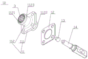
FIG. 2 is an exploded view of a push-button high-voltage quick-connect connector socket;
FIG. 3 is an exploded view of a push-button high-voltage quick-connect connector plug;
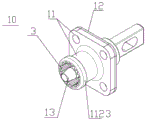
fig. 4 is a schematic overall structure diagram of a socket of a push-button high-voltage quick-plug connector;
fig. 5 is a schematic overall structure diagram of a plug of a push-button high-voltage quick-plug connector.
The socket comprises a 10-socket, a 11-socket shell, a 12-socket sealing gasket, a 13-finger-touch-preventing insulating cap, a 111-socket platform, a 112-central socket, a 1121-first end, an 1122-second end and an 1123-lug boss; 20-plug, 21-socket shell, 22-spring, 23-bayonet key, 24-central plug, 25-line ball terminal connecting part, 211-plug lower shell, 212-plug upper cover, 2111 mounting surface, 2112-key surface, 2113-line ball terminal connecting surface, 231-spring end, 232-key end, 233-spring fixing seat, 234-pressing end, 235-opening, 236-arc groove, 241-plug sealing ring, 242-jack, 243-drum spring, 251-line ball terminal sealing ring, 252-cable line ball terminal, 253-cable waterproof plug, 254-fastening nut, 3-first indexing key position and 3' -second indexing key position.
Detailed Description
In order to further understand the objects, structures, features and functions of the present invention, the following embodiments are described in detail.
Please refer to fig. 1 to 5 in combination, the utility model provides a push-button high-voltage quick-plug connector, which solves the problems of inconvenient operation, complex structure, high cost and the like caused by the connection mode of the socket and the plug bolt locking structure and the connection mode of the socket and the plug buckle locking structure in the field of the current market connectors. It comprises a socket 10 and a plug 20 which are matched with each other; the plug 20 and the socket 10 can be conveniently and quickly inserted and pulled out, and the locking is firm. The overall structure of the plug 20 when it is plugged into the receptacle 10 is shown in fig. 1.
As shown in fig. 2 and 4, the socket 10 includes a socket housing 11, a socket gasket 12, a finger-proof insulating cap 13, and a copper bar male terminal 14; the socket housing 11 comprises a socket platform 111 and a central socket 112 perpendicular to the socket platform 111, and the socket platform 111 is convenient for taking the socket 10 and applying force to the socket 10; the socket sealing gasket 12 is sleeved on the periphery of the central socket 112 and is tightly attached to the socket platform 111, and the socket sealing gasket 12 plays a role in sealing, water proofing and the like; the central socket 112 includes opposite first end 1121 and second end 1122, the copper bar male terminal 14 enters the central socket 112 from the second end 1144 and stretches out from the first end 1121, the finger-touch-preventing insulating cap 13 is installed at the head end of the copper bar male terminal 14 and covers the exposed part of the copper bar male terminal 14, the finger-touch-preventing insulating cap 13 can protect the exposed front end of the copper bar male terminal 14, the hands are prevented from being touched by mistake by accident, the electric shock risk can be avoided, and the connection safety is improved. A boss 1123 is provided on a peripheral portion of a port at a first end 1121 of the center socket 112, and the center socket 112 is a portion for connecting to the plug 20. Preferably, the inner side of the central socket 112 is provided with an inverted buckle, the middle part of the copper bar male terminal 14 is provided with a conical structure, and the copper bar male terminal 14 and the inverted buckle on the inner side of the central socket 112 are mutually clamped and fixed, so that a better locking effect can be achieved.
As shown in fig. 3 and 5, the plug 20 includes a plug housing 21, a spring 22, a click button 23, a center plug 24, and a line ball terminal connecting portion 25; the plug housing 21 comprises a plug lower housing 211 and a plug upper housing 212, the plug upper housing 212 and the plug lower housing 211 are engaged with each other to form a complete plug housing 21, the plug lower housing 211 is of a hollow structure, all plug components are mounted and fixed in the plug lower housing 211, the plug lower housing 211 comprises a mounting surface 2111, a key surface 2112 and a line pressing terminal connecting surface 2113, a central plug 24 matched with the central socket 112 is arranged on the mounting surface 2111, the central plug 24 is of a columnar structure, when the plug 20 is oppositely inserted into the socket 10, the columnar central plug 24 is correspondingly inserted into the first end of the columnar central socket 112, and a plug sealing ring 241, a socket 242 and a drum spring 243 are arranged in the columnar central plug 24; preferably, in the center plug 24, a plug sealing ring 241 is disposed at the inner bottom end of the center plug 24 for sealing, waterproofing, insulating and fastening, the insertion hole 242 is fixedly installed inside the center plug 24, and the drum spring 243 is fixed inside the insertion hole 242. Preferably, the hollow out construction of drum spring 243 has certain elasticity and contractility and has very strong electric conductivity and low resistance low heat generation nature, and the hollow out construction shrink of drum spring 243 installs in jack 242, and the hollow out construction of drum spring 243 supports and leans on in jack 242 and with jack 243 between reliable contact like this, can avoid the bad situation of contact between drum spring 243 and the jack 242, makes the utility model discloses a high voltage connector's electric signal transmission is stable, generates heat for a short time, obtains better result of use. The line ball terminal connecting part 25 is installed on the line ball terminal connecting surface 2113, and the line ball terminal connecting part 25 is used for crimping a cable so that the cable for conveying high voltage can be conveniently fixed in the plug 20 and connected with the central plug 24, and thus when the central plug 24 is plugged with the central socket 112, the connecting effect of the connector can be played, and the electrical connection is completed. The wire pressing terminal connecting portion 25 sequentially includes a wire pressing terminal sealing ring 251, a cable wire pressing terminal 252, a cable waterproof plug 253 and a fastening nut 254 from inside to outside. Preferably, a raised thread is arranged on the wire pressing terminal connection surface 2113, the wire pressing terminal sealing ring 241 is sleeved at the threaded hole to play roles of sealing, water proofing, insulating and fastening, the cable wire pressing terminal 252 extends into the plug lower housing 211 and is located below the central plug 24, the high-voltage cable is connected to the lower side of the central plug 24 by the cable wire pressing terminal 252, preferably, a jack provided with a drum spring 243 is pressed into the cable wire pressing terminal 252 through interference fit, when the plug 20 is plugged into the socket 10, the cable wire pressing terminal 252 is plugged into the central plug 24 correspondingly along with the central plug 24 and is plugged into the central socket 112, and the central plug 24 and the drum spring 243 and the jack 242 in the central socket 112 are tightly attached to each other to play excellent effects of electric conduction and signal transmission. The waterproof end cap 253 of cable is installed at the tail end of cable line ball terminal 252, and fastening nut cover 254 establishes in the outside of waterproof end cap 253 of cable and revolves to twist and fix on the bellied screw thread of line ball terminal connection face 2113, and fastening nut 254 is from taking the locking structure that moves back, can effectively avoid the cable pine of connecting to take off, has improved security and the barrier propterty of using.
As shown in fig. 3 and 5, the bayonet key 23 is a ring-shaped one-piece structure, the bayonet key 23 is sleeved on the periphery of the central plug 24 and is slidably mounted on the mounting surface 2111, the plug upper cover 212 is positioned above the bayonet key 23 and is engaged with the plug lower housing 211, i.e. the bayonet key 23 is clamped between the mounting surface 2111 of the plug lower housing 211 and the plug upper cover 212, and the plug upper cover 212 plays a role in fixing and limiting the bayonet key 23 and components in the plug lower housing 211. The bayonet key 23 comprises a spring end 231 and a key end 232 which are opposite, the spring end 231 is provided with a spring fixing column 233, one end of the spring 22 is fixed on the spring fixing column 233, the other end of the spring 22 abuts against the inner side of the connecting surface 2113 of the line pressing terminal, the key end 232 vertically extends downwards to form a pressing key 234, the pressing key 234 is parallel to the key surface 2112 and is provided with a moving gap, the center of the bayonet key 23 is provided with an opening 235, the area of the opening 235 is larger than that of the central plug 24, when the spring 22 is not compressed by any external force, one side of the opening close to the key end 232 is redundant, one side of the opening close to the spring end 231 is an arc-shaped groove 236, and a boss 1123 outside the central socket 112 is clamped in the arc-shaped groove 236, so that the bayonet key 23 can clamp the central socket 112 to;
In an embodiment, the mounting surface 2111 is provided with 2 mounting grooves, the 2 mounting grooves are symmetrically arranged on two sides of the central plug 24, the bottom of the bayonet key 23 is provided with 2 mounting blocks, the 2 mounting blocks are correspondingly mounted in the 2 mounting grooves and slide in the mounting grooves, force is applied to the pressing key 234, and the bayonet key 23 is pushed to be smoother and easier. Preferably, 2 spring fixing columns 233 are arranged on the bayonet key 23, and each spring fixing column 233 is correspondingly provided with a spring 22, so that the bayonet key 23 is stressed more uniformly, can balance stress and move inwards, and moves more stably.
When the plug 20 and the socket 10 are plugged, a finger abuts against the pressing key 234 of the bayonet key 23 and applies force to the end of the spring 22 to push, the spring 22 of the spring end 231 is compressed by extrusion, so that the bayonet key 23 integrally moves towards the spring end 231, the opening 235 in the middle of the bayonet key 23 moves towards the spring end 231, the arc-shaped groove 236 of the opening 235 close to the spring end 231 leaves the central socket 112, namely the clamping and locking effects of the bayonet key 23 on the central socket 112 on the socket 10 disappear, and the plug 20 and the socket 10 can be easily plugged in and pulled out in a straight line; when the bayonet button 23 is released, the external force applied on the spring 22 disappears, the spring 22 recovers the state before deformation, the bayonet button 23 recovers the clamping and locking functions of the central socket 112 on the socket 10, self-locking is realized, the joint is prevented from loosening, and the connection is more stable.
In one embodiment, the inner ring of the central socket 112 is provided with a first indexing key 3, the outer ring of the central plug 24 is correspondingly provided with a second indexing key 3 'matched with the inner ring of the central socket 112, when the plug 20 and the socket 10 are plugged, the first indexing key 3 on the outer ring of the central plug 24 and the second indexing key 3' on the inner ring of the central plug 112 are mutually meshed and clamped, so that the locking effect is enhanced, the plug 20 is prevented from loosening, meanwhile, the plug 20 can be effectively prevented from rotating in the socket 10, the misplugging can be prevented, and the plug 20 and the socket 10 can be adjusted to be a proper and convenient rotating plugging angle; the four flange sides of the socket are parallel to the edge of the plug.
Preferably, the engagement between the plug lower housing 211 and the plug upper cover 212 is welded together by ultrasonic welding, so that the connection reliability between the plug lower housing 211 and the plug upper cover 212 is higher.
By last, through pressing down the bayonet lock button between plug and the socket, make its elastic position through the spring compression formation remove to realize firm joint and high efficiency plug between plug and the socket. The utility model discloses a rational in infrastructure, compare in bolt locking structure operation simple and convenient more, compare in socket and plug buckle locking structure, the locking effect is better, can guarantee the stability under the heavy current operating condition, plays excellent heavy current guard action. When the bayonet lock key is pressed, the spring is compressed, and the bayonet lock key moves inwards to enable the plug to be freely inserted and pulled out without obstruction. When the plug and the socket are oppositely plugged, the inner spring is compressed by pressing the bayonet lock key, so that the boss at the head of the socket is matched with the arc-shaped groove, and the plug and the socket are quickly plugged in; when the plug and the socket are to be separated, the plug bayonet lock key is pressed down, and the socket is quickly pulled out; when the plug inserting position needs to be adjusted, the buckle key is pressed down, the plug is pulled out, the angle which needs to be inserted is adjusted again, and the plug inserting device is convenient and practical.
The present invention has been described in relation to the above embodiments, which are only examples for implementing the present invention. It should be noted that the disclosed embodiments do not limit the scope of the invention. On the contrary, all changes and modifications which do not depart from the spirit and scope of the present invention are deemed to fall within the scope of the present invention.
Claims (10)
1. A key-type high-current high-protection quick-plug connector is characterized by comprising a socket and a plug which are matched with each other;
the socket comprises a socket shell, a socket sealing gasket, a finger-touch-preventing insulating cap and a copper bar male terminal; the socket shell comprises a socket platform and a central socket perpendicular to the socket platform, the socket sealing gasket is sleeved on the periphery of the central socket and tightly attached to the socket platform, the central socket comprises a first end and a second end which are opposite, the copper bar male terminal enters the central socket from the second end and extends out of the first end, the anti-touch finger insulating cap is installed at the head end of the copper bar male terminal and covers the exposed part of the copper bar male terminal, and a boss is arranged on the periphery of a port of the first end of the central socket;
the plug comprises a plug shell, a spring, a bayonet lock key, a central plug and a line pressing terminal connecting part; the plug shell comprises a plug lower shell and a plug upper cover, the plug lower shell of the hollow structure comprises an installation surface, a key surface and a line pressing terminal connection surface, a central plug matched with the central socket is arranged on the installation surface, and a plug sealing ring, a jack and a drum spring are arranged in the columnar central plug; the bayonet lock key is of an annular integrated structure, the bayonet lock key is sleeved on the periphery of a central plug and is slidably mounted on the mounting surface, the plug upper cover is positioned above the bayonet lock key and is meshed with the plug lower shell, the bayonet lock key comprises a spring end and a key end which are opposite, the spring end is provided with a spring fixing column, one end of the spring is fixed on the spring fixing column, the other end of the spring abuts against the inner side of the connecting surface of the line pressing terminal, the key end vertically extends downwards to form a pressing key, the pressing key is parallel to the key surface and is provided with a pressing moving gap, the center of the bayonet lock key is provided with an opening, and the inner side edge of the opening is provided with an arc-shaped groove matched with the position shape of a boss of; the wire pressing terminal connecting part is installed on the wire pressing terminal connecting surface, and the wire pressing terminal connecting part comprises a wire pressing terminal sealing ring, a cable wire pressing terminal, a cable waterproof plug and a fastening nut from inside to outside in sequence.
2. The push-button high-current high-protection quick-plug connector according to claim 1, wherein the inner ring of the central socket is provided with a first indexing key position, and the outer ring of the central plug is correspondingly provided with a second indexing key position matched with the inner ring of the central socket for avoiding plug and socket rotation and plug and socket misplugging; the four flange sides of the socket are parallel to the edge of the plug.
3. The push-button high-current high-protection quick-plug connector as claimed in claim 1, wherein an inverted buckle is arranged on the inner side of the central socket, a tapered structure is arranged in the middle of the copper bar male terminal, and the copper bar male terminal and the inverted buckle on the inner side of the central socket are mutually clamped and fixed.
4. The push-button high current high protection quick connect connector of claim 1, wherein the engagement of said plug lower housing and said plug upper cover is ultrasonically welded together.
5. The push-button high-current high-protection quick-plug connector according to claim 1, wherein in the central plug, the plug sealing ring is arranged at the inner bottom end of the central plug, the jack is fixedly arranged in the central plug, and the drum spring is fixed in the jack.
6. The push-button high-current high-protection quick-plug connector according to claim 5, wherein the hollow structure of the drum spring is shrink-fitted in the jack, and the hollow structure of the drum spring abuts against the inner side of the jack and is in reliable contact with the jack.
7. The push-button high-current high-protection quick-plug connector according to claim 5, wherein a raised thread is arranged on the connecting surface of the wire pressing terminal, the sealing ring of the wire pressing terminal is sleeved on the thread, the wire pressing terminal extends into the lower plug shell and is located below the central plug, the waterproof cable plug is installed at the tail end of the wire pressing terminal, and the fastening nut is sleeved outside the waterproof cable plug and screwed and fixed on the raised thread on the connecting surface of the wire pressing terminal.
8. The push-button high current high protection quick connect connector of claim 7, wherein the drum spring loaded jack is press fit into the cable crimp terminal by interference fit.
9. The push-button high-current high-protection quick plug connector as claimed in claim 1, wherein the mounting surface is provided with 2 mounting grooves, the 2 mounting grooves are symmetrically arranged on two sides of the central plug, the bottom of the bayonet key is provided with 2 mounting blocks, and the 2 mounting blocks are correspondingly mounted in the 2 mounting grooves and slide in the mounting grooves.
10. The push-button high-current high-protection quick-plug connector as claimed in claim 1, wherein 2 spring fixing columns are arranged on the bayonet key, and a spring is correspondingly arranged on each spring fixing column.
Priority Applications (1)
| Application Number | Priority Date | Filing Date | Title |
|---|---|---|---|
| CN201921780999.0U CN210692910U (en) | 2019-10-23 | 2019-10-23 | Key-type high-current high-protection quick-plug connector |
Applications Claiming Priority (1)
| Application Number | Priority Date | Filing Date | Title |
|---|---|---|---|
| CN201921780999.0U CN210692910U (en) | 2019-10-23 | 2019-10-23 | Key-type high-current high-protection quick-plug connector |
Publications (1)
| Publication Number | Publication Date |
|---|---|
| CN210692910U true CN210692910U (en) | 2020-06-05 |
Family
ID=70886118
Family Applications (1)
| Application Number | Title | Priority Date | Filing Date |
|---|---|---|---|
| CN201921780999.0U Active CN210692910U (en) | 2019-10-23 | 2019-10-23 | Key-type high-current high-protection quick-plug connector |
Country Status (1)
| Country | Link |
|---|---|
| CN (1) | CN210692910U (en) |
-
2019
- 2019-10-23 CN CN201921780999.0U patent/CN210692910U/en active Active
Similar Documents
| Publication | Publication Date | Title |
|---|---|---|
| CN110797709A (en) | Key-type high-current high-protection quick-plug connector | |
| US10826240B2 (en) | High-voltage shielded connector assembly | |
| CN205583258U (en) | Heavy current metal connector with high pressure interlocking signal delay function | |
| CN213753292U (en) | Elbow connector for energy storage system | |
| CN208806387U (en) | A kind of anti-discharge single core connector | |
| CN109742577A (en) | A kind of resilient socket component | |
| CN107230858B (en) | Spring-touch type sealing electric plug | |
| CN109888560B (en) | Quick connector for connecting terminals | |
| CN101051718B (en) | Novel electric connector for electric tool and device | |
| CN209516094U (en) | Resilient socket component | |
| CN107342468B (en) | Electric connection, vehicular electrical appliance electric binding post and vehicular electrical appliance electric connection structure | |
| CN210692910U (en) | Key-type high-current high-protection quick-plug connector | |
| CN219833196U (en) | Energy storage connector | |
| CN210224453U (en) | Electric connector plug | |
| CN111355082A (en) | Connector capable of transmitting large current in bilateral locking mode | |
| CN216814106U (en) | Waterproof relay connection structure of LED lamp area | |
| CN210326265U (en) | Power supply connector | |
| CN201758153U (en) | Earthing structure of battery cabinet and battery cabinet employing same | |
| CN110957617B (en) | Safety socket | |
| CN112821092A (en) | High-current connector | |
| CN209896313U (en) | Quick connector for connecting terminal | |
| CN1181645A (en) | Rotary elastic electrical connection method and device | |
| CN210052908U (en) | Plug connector with sealing function | |
| CN216773677U (en) | Resistance to compression type electronic connector | |
| CN2901624Y (en) | Novel electric connector for electric tools and equipments |
Legal Events
| Date | Code | Title | Description |
|---|---|---|---|
| GR01 | Patent grant | ||
| GR01 | Patent grant |