CN210680148U - Voucher binding means for financial affairs - Google Patents
Voucher binding means for financial affairs Download PDFInfo
- Publication number
- CN210680148U CN210680148U CN201920943881.9U CN201920943881U CN210680148U CN 210680148 U CN210680148 U CN 210680148U CN 201920943881 U CN201920943881 U CN 201920943881U CN 210680148 U CN210680148 U CN 210680148U
- Authority
- CN
- China
- Prior art keywords
- punching
- base
- spring
- voucher binding
- depression bar
- Prior art date
- Legal status (The legal status is an assumption and is not a legal conclusion. Google has not performed a legal analysis and makes no representation as to the accuracy of the status listed.)
- Active
Links
Images


Landscapes
- Clamps And Clips (AREA)
Abstract
The utility model discloses a financial voucher binding device in the technical field of binding devices, which comprises a base and support legs, the support legs are symmetrically arranged at the bottom end of the base, the clamping mechanisms are symmetrically arranged at the left rear side and the right rear side of the top end of the base, the utility model realizes punching of the punching nail by pressing the hand ring to drive the pressing rod to move downwards, the transmission process of the structural force is simple and direct, so that the punching process is more reasonable and labor-saving, meanwhile, the fixed rope can be directly driven to pass through the financial voucher laminated layer when the hole is punched by arranging the leading rope hook groove on the wall of the punching needle, thereby facilitating the user to complete the subsequent fixing process, effectively compacting and fixing the material to be fixed through the arranged clamping mechanism, the punching mechanism in the device can slide left and right along the base, thereby can realize the porous process of punching under the clamping state, this kind of mode of punching can effectively avoid traditional removal paper to carry out the crisscross problem of paper that porous punching caused.
Description
Technical Field
The utility model relates to a binding means technical field specifically is a voucher binding means for financial affairs.
Background
The financial voucher is written certificate which is compiled according to a certain format and is used for registering an accounting book, is mainly used for recording the occurrence of economic business, making clear economic responsibility and is used as the written certificate for keeping accounts, so that the financial voucher is often bound and properly stored. The existing financial voucher binding device adopts hot melting binding, has higher manufacturing cost and needs to consume a large amount of electric energy.
For example, chinese patent application No. CN201420698141.0 discloses a financial voucher binding apparatus, which relates to a binding apparatus, in particular to a financial voucher binding apparatus. The utility model discloses a solve current financial voucher binding means and adopt the hot melt to bind, its cost is higher, need consume the problem of a large amount of electric energy moreover. The utility model discloses a base, the cam, the camshaft, the pedestal, the needle tubing punches, reset spring, uide bushing and uide bushing support, the base level sets up, the camshaft is installed on the pedestal, the pedestal is installed on the upper surface of base, the camshaft suit is on the camshaft, uide bushing support mounting is on the upper surface of base, the uide bushing is installed on the uide bushing support, the needle tubing cartridge that punches is in the uide bushing, and the needle tubing that punches is located the cam under, reset spring suit is on the needle tubing that punches, and reset spring's upper end is connected with the boss on the needle tubing upper end lateral wall that punches, reset spring's lower extreme is connected with the up end of uide bushing. The utility model is used for the financial affairs field.
Although this kind of binding means simple structure, convenient operation, low in manufacturing cost, thereby the device makes the cam oppression needle tubing that punches punch through rotating the crank, this kind of operating mode is because the transmission process of power is unreasonable, it is very hard to cause to punch, damage transmission structure very easily, the device is whole to be difficult to realize laborsaving rapid punching process, the practicality is extremely low, after the device punches simultaneously, it is inconvenient still to need the maintenance financial voucher position of user's minuscule wing, the manual threading of rethread or the nail is fixed with the financial voucher, this process operation is comparatively inconvenient.
Based on this, the utility model designs a voucher binding means for financial affairs to solve above-mentioned problem.
SUMMERY OF THE UTILITY MODEL
An object of the utility model is to provide a voucher binding means for financial affairs to solve the problem in the above-mentioned background art.
In order to achieve the above object, the utility model provides a following technical scheme: the utility model provides a voucher binding means for financial affairs, including base and stabilizer blade, the stabilizer blade symmetry sets up in the base bottom, base top left side rear side right symmetry is provided with clamping mechanism, base rear end sliding connection has the support slide, support slide top middle part is provided with the L template, L template roof middle part activity is run through and is provided with the depression bar, the depression bar top is provided with the clamp plate, both ends symmetry is provided with the pressure ring about the clamp plate, be provided with first spring between clamp plate bottom and the L template, and first spring wire-wound depression bar, the depression bar lower part is provided with spacing dish, the depression bar bottom is provided with the nail that punches.
Preferably, clamping mechanism is including the riser, the riser top is provided with the diaphragm, diaphragm bottom bilateral symmetry is provided with the spring telescopic link, the spring telescopic link bottom is connected with splint, diaphragm top middle part is provided with limit threaded rod, limit threaded rod top is provided with the carousel.
Preferably, the spring telescopic link is including fixed sleeve, the fixed sleeve inner chamber slides and is provided with the telescopic link, and the telescopic link bottom runs through fixed sleeve bottom, fixed sleeve and telescopic link are outer to have connect the second spring around having.
Preferably, the part of the punching nail close to the needle point is provided with a rope guiding hook groove for threading, a strip-shaped through hole is formed in the top end of the base corresponding to the moving track of the punching nail, and the needle point is prevented from impacting the base and being damaged.
Preferably, the support slide is provided with a locking screw for fixing the position of the support sliding sleeve, the top end of the base is provided with a sliding groove, and the support slide is provided with a flange matched with the sliding groove for limiting the sliding support slide.
Preferably, be provided with the rubber grip on pressing the bracelet, the person of facilitating the use holds.
Compared with the prior art, the beneficial effects of the utility model are that: the utility model discloses a push down the bracelet and drive the depression bar and move down, thereby realize punching the nail and punch, the transmission process of this structural force is simple direct, make the process of punching more reasonable laborsaving, simultaneously through setting up the messenger hook groove on the needle wall that punches, can directly drive fixed rope and pass financial document stromatolite when punching, thereby the person of facilitating the use accomplishes subsequent fixed process, can effectively compact the fixed material of treating through holding the mechanism with setting up, the mechanism of punching in this device, can be along base horizontal slip, thereby can realize the porous process of punching under the clamping status, this kind of mode of punching can effectively avoid traditional removal paper to carry out the crisscross problem of paper that porous punching caused.
Drawings
In order to more clearly illustrate the technical solutions of the embodiments of the present invention, the drawings used in the description of the embodiments will be briefly introduced below, and it is obvious that the drawings in the following description are only some embodiments of the present invention, and it is obvious for those skilled in the art that other drawings can be obtained according to these drawings without creative efforts.
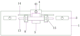
FIG. 1 is a schematic structural view of the present invention;
FIG. 2 is a top view of the present invention
FIG. 3 is an enlarged schematic view of the utility model at A;
FIG. 4 is a schematic view of the structure of the clamping mechanism of the present invention;
fig. 5 is the structure schematic diagram of the spring telescopic rod of the present invention.
In the drawings, the components represented by the respective reference numerals are listed below:
1-base, 2-support leg, 3-clamping mechanism, 4-support sliding plate, 5-L-shaped plate, 6-pressure rod, 7-pressure plate, 8-pressure hand ring, 9-leading rope hook groove, 10-first spring, 11-limiting plate, 12-punching nail, 13-strip-shaped through hole, 14-sliding groove, 15-rubber grip sleeve, 31-vertical plate, 32-transverse plate, 33-spring telescopic rod, 331-fixed sleeve, 332-telescopic rod, 333-second spring, 34-clamping plate, 35-limiting threaded rod, 36-rotary plate and 41-locking screw rod.
Detailed Description
The technical solutions in the embodiments of the present invention will be described clearly and completely with reference to the accompanying drawings in the embodiments of the present invention, and it is obvious that the described embodiments are only some embodiments of the present invention, not all embodiments. Based on the embodiments of the present invention, all other embodiments obtained by a person of ordinary skill in the art without creative efforts belong to the protection scope of the present invention.
Referring to fig. 1-3, the present invention provides a technical solution: the utility model provides a voucher binding means for financial affairs, including base 1 and stabilizer blade 2, 2 symmetries of stabilizer blade set up in 1 bottom of base, 1 top left side rear side bilateral symmetry of base is provided with clamping mechanism 3, 1 rear end sliding connection of base has supporting slide 4, 4 top middle parts of supporting slide are provided with L template 5, 5 roof middle parts activities of L template run through and are provided with depression bar 6, 6 tops of depression bar are provided with clamp plate 7, 7 left and right ends symmetries of clamp plate are provided with pressure ring 8, be provided with first spring 10 between 7 bottoms of clamp plate and the L template 5, first spring 10 wire wrapping depression bar 6, 6 lower parts of depression bar are provided with spacing dish 11, 6 bottoms of depression bar are provided with.
Wherein, clamping mechanism 3 is including riser 31, riser 31 top is provided with diaphragm 32, diaphragm 32 bottom bilateral symmetry is provided with spring telescopic link 33, spring telescopic link 33 bottom is connected with splint 34, diaphragm 32 top middle part is provided with limit threaded rod 35, limit threaded rod 35 top is provided with carousel 36, spring telescopic link 33 is including fixed sleeve 331, the sliding of fixed sleeve 331 inner chamber is provided with telescopic link 332, the bottom of fixed sleeve 331 is run through to telescopic link 332 bottom, fixed sleeve 331 and telescopic link 332 peripheral wiring have second spring 333, nail 12 that punches is close to needle point department and is provided with rope guiding hook groove 9, the activity orbit that the nail 12 that punches that corresponds in base 1 top is provided with bar through-hole 13, be provided with locking screw 41 on the slide 4, spout 14 has been seted up on base 1 top, be provided with on the slide 4 with spout 14 complex flange, be provided with rubber on the hand pressing ring.
One specific application of this embodiment is: this device is voucher binding means for financial affairs. The use principle of the device is as follows:
when specifically using, will wait to punch and place in base 1 top after the financial voucher material arrangement of binding is neat for paper material side of punching is close to clamping mechanism 3, then rotates limit threaded rod 35, and splint 34 is pushed down to the gag lever post 35 bottom, makes splint 34 be close to and presss from both sides tight bottom paper material, and this in-process spring telescopic link 33 extension, second spring 333 is in tensile state. Then, the punching position is selected, the support slide 4 is moved, the support slide 4 slides left and right along the slide groove 14 on the base 1, the support slide 4 is moved so that the punching pin 12 is aligned with the punching point, then the locking screw 41 is screwed to fix the support sliding plate 4, then the fixing binding rope is sleeved in the rope guiding hook groove 9, then the pressing ring 8 is held by two hands to move downwards, the pressing plate 7 pushes the pressing rod, the pressing rod 6 pushes the punching nail 12, and then punch nail 12 and move down and punch on paper material, during the punching, fixed wiring rope runs through paper material along with punching pin most advanced (because the coupler body of the messenger hook groove 9 that sets up is the inversion and sets up, therefore when punching pin 12 returns, paper material can be released fixed wiring rope from messenger hook groove 9, if the rope body is not released, still can make punching pin most advanced from the base bottom pop out, then manually pull out the rope body), then utilize the rope body to bind this department drilling of fixed department. When the next hole is drilled, the locking screw 41 is unscrewed, the position of the supporting sliding plate 4 is adjusted, and the drilling step is repeated.
In the description herein, references to the description of "one embodiment," "an example," "a specific example," etc., mean that a particular feature, structure, material, or characteristic described in connection with the embodiment or example is included in at least one embodiment or example of the invention. In this specification, the schematic representations of the terms used above do not necessarily refer to the same embodiment or example. Furthermore, the particular features, structures, materials, or characteristics described may be combined in any suitable manner in any one or more embodiments or examples.
The preferred embodiments of the present invention disclosed above are intended only to help illustrate the present invention. The preferred embodiments are not intended to be exhaustive or to limit the invention to the precise embodiments disclosed. Obviously, many modifications and variations are possible in light of the above teaching. The embodiments were chosen and described in order to best explain the principles of the invention and its practical applications, to thereby enable others skilled in the art to best understand the invention for and utilize the invention. The present invention is limited only by the claims and their full scope and equivalents.
Claims (6)
1. The utility model provides a voucher binding means for financial affairs, including base (1) and stabilizer blade (2), its characterized in that: stabilizer blade (2) symmetry sets up in base (1) bottom, base (1) top left side rear side right symmetry is provided with clamping mechanism (3), base (1) rear end sliding connection has supporting slide (4), supporting slide (4) top middle part is provided with L template (5), L template (5) roof middle part activity is run through and is provided with depression bar (6), depression bar (6) top is provided with clamp plate (7), both ends symmetry is provided with presses bracelet (8) about clamp plate (7), be provided with first spring (10) between clamp plate (7) bottom and L template (5), and first spring (10) wire-wound depression bar (6), depression bar (6) lower part is provided with spacing dish (11), depression bar (6) bottom is provided with the nail of punching (12).
2. A financial voucher binding apparatus according to claim 1 wherein: clamping mechanism (3) are including riser (31), riser (31) top is provided with diaphragm (32), diaphragm (32) bottom bilateral symmetry is provided with spring telescopic link (33), spring telescopic link (33) bottom is connected with splint (34), diaphragm (32) top middle part is provided with limit threaded rod (35), limit threaded rod (35) top is provided with carousel (36).
3. A financial voucher binding apparatus according to claim 2 wherein: the spring telescopic rod (33) comprises a fixed sleeve (331), a telescopic rod (332) is arranged in an inner cavity of the fixed sleeve (331) in a sliding mode, the bottom end of the telescopic rod (332) penetrates through the bottom end of the fixed sleeve (331), and a second spring (333) is connected between the fixed sleeve (331) and the telescopic rod (332) in a surrounding mode.
4. A financial voucher binding apparatus according to claim 1 wherein: the part, close to the needle point, of the punching nail (12) is provided with a guide rope hook groove (9), and a strip-shaped through hole (13) is formed in the top end of the base (1) corresponding to the moving track of the punching nail (12).
5. A financial voucher binding apparatus according to claim 1 wherein: the supporting sliding plate (4) is provided with a locking screw rod (41), the top end of the base (1) is provided with a sliding groove (14), and the supporting sliding plate (4) is provided with a flange matched with the sliding groove (14).
6. A financial voucher binding apparatus according to claim 1 wherein: the pressing ring (8) is provided with a rubber holding sleeve (15).
Priority Applications (1)
| Application Number | Priority Date | Filing Date | Title |
|---|---|---|---|
| CN201920943881.9U CN210680148U (en) | 2019-06-21 | 2019-06-21 | Voucher binding means for financial affairs |
Applications Claiming Priority (1)
| Application Number | Priority Date | Filing Date | Title |
|---|---|---|---|
| CN201920943881.9U CN210680148U (en) | 2019-06-21 | 2019-06-21 | Voucher binding means for financial affairs |
Publications (1)
| Publication Number | Publication Date |
|---|---|
| CN210680148U true CN210680148U (en) | 2020-06-05 |
Family
ID=70884994
Family Applications (1)
| Application Number | Title | Priority Date | Filing Date |
|---|---|---|---|
| CN201920943881.9U Active CN210680148U (en) | 2019-06-21 | 2019-06-21 | Voucher binding means for financial affairs |
Country Status (1)
| Country | Link |
|---|---|
| CN (1) | CN210680148U (en) |
Cited By (2)
| Publication number | Priority date | Publication date | Assignee | Title |
|---|---|---|---|---|
| CN112320448A (en) * | 2020-10-23 | 2021-02-05 | 温州职业技术学院 | High-efficient type test paper becomes bundle packing apparatus |
| CN114248575A (en) * | 2021-12-27 | 2022-03-29 | 赵勤阳 | Binding means for financial affairs invoice |
-
2019
- 2019-06-21 CN CN201920943881.9U patent/CN210680148U/en active Active
Cited By (2)
| Publication number | Priority date | Publication date | Assignee | Title |
|---|---|---|---|---|
| CN112320448A (en) * | 2020-10-23 | 2021-02-05 | 温州职业技术学院 | High-efficient type test paper becomes bundle packing apparatus |
| CN114248575A (en) * | 2021-12-27 | 2022-03-29 | 赵勤阳 | Binding means for financial affairs invoice |
Similar Documents
| Publication | Publication Date | Title |
|---|---|---|
| CN210680148U (en) | Voucher binding means for financial affairs | |
| CN111546767B (en) | Oil drum sign lithography apparatus | |
| CN210680142U (en) | Financial accounting device of stamping for economic management | |
| CN212489056U (en) | But laboratory table of automatically regulated height, length | |
| CN210745683U (en) | PCB pressing jig | |
| CN215868309U (en) | Teaching aid | |
| CN215705247U (en) | Fixing device for book binding | |
| CN212949789U (en) | Accounting document binding means | |
| CN213782446U (en) | Auxiliary device for crimping of ground wire of power transmission line | |
| CN210133144U (en) | Multifunctional transportation device for fitness equipment | |
| CN209520975U (en) | A kind of accounting archives perforating device | |
| CN208698153U (en) | A kind of small silk screen printing equipment | |
| CN202684987U (en) | Accounting document punching device | |
| CN212598569U (en) | Data line cutting equipment | |
| CN218536017U (en) | Greeting card hot stamping machine capable of limiting | |
| CN218364298U (en) | Positioning fixture for pin shaft | |
| CN113910802B (en) | Financial affairs voucher binding means | |
| CN218519429U (en) | Portable perforating device | |
| CN220784232U (en) | Document punching device | |
| CN211467816U (en) | Cloth clamping structure for printing machine | |
| CN213007097U (en) | Printing machine material collecting device convenient to selective examination | |
| CN220808954U (en) | Typesetting mechanism for printing bookbinding machine | |
| CN217507903U (en) | PIN pulling device for socket | |
| CN211542993U (en) | Flattening and binding device for accounting receipts | |
| CN211065533U (en) | Primary school's chinese reading board |
Legal Events
| Date | Code | Title | Description |
|---|---|---|---|
| GR01 | Patent grant | ||
| GR01 | Patent grant |