Outdoor monitor terminal mounting structure of intelligence
Technical Field
The utility model relates to a monitor terminal installs the field, especially relates to an outdoor monitor terminal mounting structure of intelligence.
Background
Present monitor terminal mainly fixes on the monitoring pole, and monitor terminal's terrain clearance is higher, needs the staff operation of ascending a height when maintenance, and the useful cat ladder of the measure of ascending a height, scaffold frame or the operation car of ascending a height has not only constituted the threat to staff's life safety, has also caused the increase of maintenance, cost of maintenance.
SUMMERY OF THE UTILITY MODEL
An object of the utility model is to overcome the above problem that prior art exists, provide an outdoor monitor terminal mounting structure of intelligence.
For realizing above-mentioned technical purpose, reach above-mentioned technological effect, the utility model discloses a following technical scheme realizes:
the utility model provides an outdoor monitor terminal mounting structure of intelligence, including the mount table that is used for installing monitor terminal, be the stay tube of Z type, be used for installing the hollow pole setting of stay tube, set up in install the bearing in the bearing frame of hollow pole setting top one side, the first interference fit of stay tube is in the inner circle of bearing, the first rigid coupling of stay tube has the location fluted disc, the first cover of stay tube still have can remove and with location fluted disc complex location chuck, the location chuck passes through the screw and installs in the side of hollow pole setting, set up in the round bar of mount table bottom rotates and installs in the drum of rigid coupling in the stay tube second head to one side spiro union of drum has the fastening bolt who is used for fastening the round bar.
Furthermore, a plurality of tooth grooves distributed according to an annular array are formed in the end face of the positioning fluted disc close to the outer edge of the positioning fluted disc, at least one tooth matched with the tooth grooves is arranged on the end face of the positioning chuck close to the outer edge of the positioning chuck, and the tooth is clamped into the tooth grooves to enable the positioning fluted disc to be relatively fixed on the side face of the hollow vertical rod.
Furthermore, the cross section of the hollow vertical rod is square.
Furthermore, a bottom plate perpendicular to the long axis of the hollow vertical rod is arranged at the bottom end of the hollow vertical rod, and a reinforcing plate is fixedly connected between the bottom plate and the side face of the hollow vertical rod.
Further, the height of the hollow vertical rod is less than or equal to 2 meters.
Furthermore, the mounting table comprises a mounting plate, a strip-shaped hinged block with hinged holes and a U-shaped hinged block with hinged holes, the strip-shaped hinged block is fixedly connected to the center of the bottom end of the mounting plate, one end of the strip-shaped hinged block with the hinged holes is arranged in an opening of the U-shaped hinged block, the hinged holes of the strip-shaped hinged block and the hinged holes of the U-shaped hinged block are connected in series through damping rotating shafts, and the round rod is vertically and fixedly connected to the center of the bottom end of the U-shaped hinged block.
The utility model has the advantages that: set up the stay tube of hollow pole setting and Z type to adopt location fluted disc and positioning chuck matched with locate mode to install the stay tube in one side of hollow pole setting, make the stay tube can rotate in vertical direction, when needs maintain monitor terminal, during the maintenance, adjust monitor terminal to the staff can stand the height that just can operate on ground through rotating the stay tube can, do not need the staff operation of ascending a height, reduce the threat to staff's life safety, reduce the maintenance, cost of maintenance.
Drawings
The accompanying drawings, which are included to provide a further understanding of the invention and are incorporated in and constitute a part of this application, illustrate embodiment(s) of the invention and together with the description serve to explain the invention without undue limitation to the invention. In the drawings:
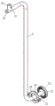
fig. 1 is a schematic structural view of a support tube in a normal state according to an embodiment of the present invention;
FIG. 2 is a schematic structural view of the embodiment of the present invention in which the supporting tube is in a maintenance state;
fig. 3 is a schematic structural view of a hollow upright rod in an embodiment of the present invention;
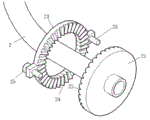
FIG. 4 is a schematic structural view of a support tube in an embodiment of the present invention;
FIG. 5 is a schematic view of a part of the structure of the support tube in the embodiment of the present invention;
fig. 6 is a schematic structural diagram of a mounting table in an embodiment of the present invention.
Detailed Description
The present invention will be described in detail below with reference to the accompanying drawings in conjunction with embodiments.
In the description of the present invention, it is to be understood that the terms "open hole", "upper", "lower", "thickness", "top", "middle", "length", "inner", "around", and the like, indicate positional or positional relationships, are merely for convenience in describing the present invention and to simplify the description, and do not indicate or imply that the components or elements referred to must have a particular orientation, be constructed and operated in a particular orientation, and therefore should not be construed as limiting the present invention.
As shown in fig. 1 to 6, an outdoor monitor terminal mounting structure of intelligence, including the mount table 3 that is used for installing monitor terminal, be the stay tube 2 of Z type, be used for installing the hollow pole setting 1 of stay tube 2, set up and install bearing 4 in the bearing frame 11 of hollow pole setting 1 top one side, the interference fit of first end of stay tube 2 is in the inner circle of bearing, the first end rigid coupling of stay tube 2 has location fluted disc 21, the first end of stay tube 2 still overlaps and has can move and with location fluted disc 21 complex location chuck 23, location chuck 23 passes through the screw 25 and installs the side at hollow pole setting 1, set up in the drum 26 of round bar 35 rotation installation in the rigid coupling in the second of stay tube 2 bottom of mount table 3, and one side spiro union of drum 26 has fastening bolt 27 that is used for fastening round bar 35.
The end face of the positioning fluted disc 21 is provided with 36 tooth grooves 22 which are distributed according to an annular array and are close to the outer edge of the positioning fluted disc, the end face of the positioning chuck 23 is provided with 36 teeth 24 which are matched with the tooth grooves 22 and are close to the outer edge of the positioning chuck, and the teeth 24 are clamped in the tooth grooves 22 to ensure that the positioning fluted disc 21 is relatively fixed on the side face of the hollow upright rod 1.
The cross section of the hollow upright rod 1 is square.
The bottom end of the hollow upright rod 1 is provided with a bottom plate 12 vertical to the long axis of the hollow upright rod 1, and a reinforcing plate 13 is fixedly connected between the bottom plate 12 and the side surface of the hollow upright rod 1.
The height of the hollow upright stanchion 1 is less than or equal to 2 meters, so that workers with the ordinary height of 1.6-1.9 meters can operate the support pipe 2 and the screw 25 by standing on the ground.
The mounting table 3 comprises a mounting plate 31, a strip-shaped hinge block 32 with hinge holes and a U-shaped hinge block 33 with hinge holes, wherein the strip-shaped hinge block 32 is fixedly connected at the center of the bottom end of the mounting plate 31, one end of the strip-shaped hinge block 32 with the hinge holes is arranged in the opening of the U-shaped hinge block 33, the hinge holes of the strip-shaped hinge block 32 are connected with the hinge holes of the U-shaped hinge block 33 in series through damping rotating shafts 34, and a round rod 35 is vertically fixedly connected at the center of the bottom end of the U-shaped hinge block 33.
A rubber wire sleeve 28 is plugged in the second end of the support tube 2, and a cable connected with the monitoring terminal is threaded into the support tube 2 and the hollow upright rod 1 from the rubber wire sleeve 28.
Description of the operation: firstly, a screw 25 for connecting a positioning chuck 23 and a hollow upright rod 1 is unscrewed, so that teeth 24 on the positioning chuck 23 are completely pulled out from a tooth groove 22 on a positioning tooth disc 21, then a supporting tube 2 is rotated, a monitoring terminal installed on an installation platform 3 is arranged at a height which can be operated by a worker standing on the ground, then the screw 25 is screwed, so that the teeth 24 are clamped with the tooth groove 22, after maintenance and repair are finished, the screw 25 is unscrewed again, the teeth 24 on the positioning chuck 23 are completely pulled out from the tooth groove 22 on the positioning tooth disc 21, the supporting tube 2 is rotated, so that the monitoring terminal is positioned at the height position during working, and then the screw 25 is screwed.
In the description herein, references to the description of "one embodiment," "an example," "a specific example," etc., mean that a particular feature, structure, material, or characteristic described in connection with the embodiment or example is included in at least one embodiment or example of the invention. In this specification, the schematic representations of the terms used above do not necessarily refer to the same embodiment or example. Furthermore, the particular features, structures, materials, or characteristics described may be combined in any suitable manner in any one or more embodiments or examples.
The foregoing shows and describes the general principles, essential features, and advantages of the invention. It will be understood by those skilled in the art that the present invention is not limited to the above embodiments, and that the foregoing embodiments and descriptions are provided only to illustrate the principles of the present invention without departing from the spirit and scope of the present invention.