CN210652449U - Multifunctional drawing ruler for students - Google Patents
Multifunctional drawing ruler for students Download PDFInfo
- Publication number
- CN210652449U CN210652449U CN201822198272.3U CN201822198272U CN210652449U CN 210652449 U CN210652449 U CN 210652449U CN 201822198272 U CN201822198272 U CN 201822198272U CN 210652449 U CN210652449 U CN 210652449U
- Authority
- CN
- China
- Prior art keywords
- ring
- ruler
- fixedly connected
- angle
- rotating ring
- Prior art date
- Legal status (The legal status is an assumption and is not a legal conclusion. Google has not performed a legal analysis and makes no representation as to the accuracy of the status listed.)
- Expired - Fee Related
Links
Images

Landscapes
- Length-Measuring Instruments Using Mechanical Means (AREA)
- Drawing Aids And Blackboards (AREA)
Abstract
The utility model belongs to the technical field of learning tool technique and specifically relates to a multi-functional student's ruler of drafting, including base, ruler and swivel ring B, base up end rigid coupling has the fixed axle, and the fixed axle is outer by lower supreme rigid coupling respectively have first spacing ring and second spacing ring, and the fixed axle has cup jointed the swivel ring A who suits the matching with it in the first spacing ring outside, ruler fixed connection is at swivel ring A right side terminal surface, and the fixed axle has cup jointed the swivel ring B who suits the matching with it in the second spacing ring outside, and swivel ring B upside right side terminal surface rigid coupling has the angle square, and the angle square is connected with the threaded rod through the bearing near swivel ring B one end terminal surface in leading to the groove, and the screw thread has cup jointed the slider on the threaded rod. The utility model has the advantages of reasonable design, both can carry out the drawing of sharp and the measurement of line segment length fast, can realize the drawing of fixed radius circle again, can also carry out the drawing and the measurement of angle, can carry out the drawing of fixed radius circular arc simultaneously to can realize the multiple requirement of chi rule drawing.
Description
Technical Field
The utility model belongs to the technical field of learning tools technique and specifically relates to a multi-functional student's drafting scale.
Background
Ruler-compass drawing is the basic ability of geometric learning of middle school at present, namely utilizes ruler and compasses to carry out drawing, and this must ask students to carry ruler and compasses, not only occupation space, and cause easily and lose in addition, because the compasses have the stitch, easily prick the student. In the utility model patent of china utility model with publication number CN207772708U, a multi-functional ruler for high school was published, through spout, slider, support column, supporting shoe and put between the hole of a pen cooperation, can draw the suitable circle of size on paper, make the student need not take a compasses to school again, it is more convenient. But when using this utility model, need fix the slider through screwing up the bolt, therefore the operation is got up more complicatedly, if screw up tightly enough and cause the slider not hard up easily for the figure of drawing is accurate inadequately, in addition, utilizes the device to carry out drawing of fixed angle, needs the cooperation protractor to remove the chi body, and is inconvenient, so the device still needs further improvement.
Disclosure of Invention
The utility model aims at overcoming above-mentioned technical shortcoming and providing a multi-functional student's drafting scale, both can carry out the drawing of sharp and the measurement of line segment length fast, can realize the drawing of fixed radius circle again, can also carry out the drawing and the measurement of angle, can carry out the drawing of fixed radius circular arc simultaneously to can realize the multiple requirement of ruler rule drawing.
The utility model provides a technical scheme that technical problem adopted does: a multifunctional student drafting scale comprises a base, a ruler and a rotating ring B, wherein a fixed shaft is fixedly connected to the upper end face of the base, a first limiting ring and a second limiting ring are fixedly connected to the outer portion of the fixed shaft from bottom to top respectively, a pressing block is fixedly connected to the top end of the fixed shaft, communicated positioning holes are formed in the centers of the pressing block, the fixed shaft and the base, the position of a circle center can be rapidly determined through the positioning holes, the fixed shaft is sleeved with the rotating ring A matched with the first limiting ring at the outer side of the first limiting ring, the ruler is fixedly connected to the right end face of the rotating ring A, first scale marks are carved on the ruler and can be used for measuring the length of a line, the rotating ring B and the rotating ring A can rotate relatively, an angle square is fixedly connected to the right upper end face of the rotating ring B, a through groove is formed in the middle of the angle square, a positioning ring is fixedly connected to one end face, far, the threaded rod penetrates through the positioning ring and is fixedly connected with the rotating handle at one end far away from the rotating ring B, the positioning ring can be used for preventing the threaded rod from shaking under external force, a sliding block is sleeved on the threaded rod in a threaded manner, the right front end of the sliding block is fixedly connected with a connecting rod above the angle square, the tail end of the connecting rod is fixedly connected with a fixing block, a pen placing hole is formed in the center of the fixing block, the ruler, the rotating ring A, the angle square, the rotating ring B and the connecting rod are all made of transparent plastic materials, a second scale mark is carved on the angle square and used for marking the distance from the circle center of the pen placing hole to the circle center of the rotating ring B so as to mark the current radius, an angle line is carved on the rotating ring A, an angle alignment line is carved on the rotating ring B and used for displaying the angle between the current angle square and the ruler, a radius alignment line is carved on the connecting rod, the ruler is overlapped with the angle ruler, the rotating handle is rotated to enable the sliding block to slide along the through groove, the sliding block is enabled to slide to a proper position according to the radius alignment line and the second scale line, a pen is placed in the pen placing hole, the pressing block is pressed, the angle ruler and the ruler are simultaneously shifted by the pen, drawing of a circle with a fixed radius can be achieved, the ruler is pressed by one hand, the angle ruler is rotated by the other hand, the open angle of the angle ruler can be rapidly determined through the angle line and the angle alignment line, drawing and measuring of the angle are conducted, the rotating handle is rotated to enable the sliding block to slide along the through groove, the sliding block is enabled to slide to a proper position according to the radius alignment line and the second scale line, then the ruler is pressed, the pen is placed in the pen placing hole, the angle ruler is shifted by the pen, drawing of a circular arc with a fixed radius can be conducted.
Furthermore, the lower end face of the base is fixedly connected with a rubber anti-slip pad matched with the base to prevent slipping.
Furthermore, a rubber ring is fixedly connected in the pen placing hole, and the rubber ring has certain elasticity and can be clamped to adapt to different pens.
The utility model discloses the beneficial effect who has is: the utility model has the advantages of reasonable design, both can carry out the drawing of sharp and the measurement of line segment length fast, can realize the drawing of fixed radius circle again, can also carry out the drawing and the measurement of angle, can carry out the drawing of fixed radius circular arc simultaneously to can realize the multiple requirement of chi rule drawing.
Drawings
Fig. 1 is a schematic structural diagram of the present invention.
Fig. 2 is a structural sectional view of the rotating ring a and the rotating ring B of the present invention.
Figure 3 is a structural section view of the slider of the present invention.
Detailed Description
The present invention will be described in detail below with reference to fig. 1 to 3.
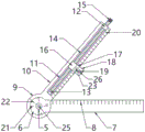
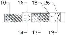
As shown in fig. 1-3, the utility model comprises a base 1, a ruler 7 and a rotating ring B9, wherein the upper end face of the base 1 is fixedly connected with a fixed shaft 2, the fixed shaft 2 is fixedly connected with a first limit ring 3 and a second limit ring 4 from bottom to top, and the top end is fixedly connected with a pressing block 5, the centers of the pressing block 5, the fixed shaft 2 and the base 1 are provided with a communicating positioning hole 25, the center position of the circle can be rapidly determined through the positioning hole 25, the fixed shaft 2 is sleeved with a rotating ring a6 matched with the first limit ring 3 at the outer side, the ruler 7 is fixedly connected with the right end face of the rotating ring a6, a first scale 8 is carved on the ruler 7 and can be used for measuring the length of the line segment, the fixed shaft 2 is sleeved with a rotating ring B9 matched with the second limit ring 4 at the outer side, the rotating ring B9 and the rotating ring a6 can rotate relatively, the right upper end face of the rotating ring B9 is fixedly connected with, the middle of the angle square 10 is provided with a through groove 11, one end of the angle square 10, which is far away from the rotating ring B9, of the through groove 11 is fixedly connected with a positioning ring 12, one end face, which is close to the rotating ring B9, of the angle square 10 is connected with a threaded rod 14 through a bearing 13, one end, which is far away from the rotating ring B9, of the angle square 10 passes through the positioning ring 12 and is fixedly connected with a rotating handle 15, the positioning ring 12 can be used for preventing the threaded rod 14 from shaking under external force, the threaded rod 14 is in threaded sleeve connection with a sliding block 16, the right front end of the sliding block 16 is fixedly connected with a connecting rod 17 above the angle square 10, the tail end of the connecting rod 17 is fixedly connected with a fixing block 18, the center of the fixing block 18 is provided with a pen placing hole 19, the straight scale 7, the rotating ring A6, the angle square 10, the rotating ring B9 and the connecting rod 17 are all made of transparent plastic materials, the angle square 10 is engraved, an angle alignment line 22 is carved on the rotating ring B9 for displaying the angle between the current angle square 10 and the straight ruler 7, and a radius alignment line 23 is carved on the connecting rod 17 for quickly determining the current radius.
In this embodiment, a rubber anti-slip pad 24 that is suitable for the base 1 is fixed to the lower end surface of the base 1 to prevent slipping.
In this embodiment, a rubber ring 26 is fixedly connected in the pen placing hole 19, and the rubber ring 26 has a certain elasticity and can be clamped to adapt to different pens.
When the utility model is used, the straight ruler 7 can be used for drawing straight lines and measuring the length of line segments rapidly; the ruler 7 is overlapped with the angle square 10, the rotating handle 15 is rotated to enable the sliding block 16 to slide along the through groove 11, the sliding block 16 is enabled to slide to a proper position by referring to the radius guideline 23 and the second scale mark 20, a pen is placed in the pen placing hole 19, the pressing block 5 is pressed, the angle square 10 and the ruler 7 are simultaneously shifted by the pen, and drawing of a circle with a fixed radius can be achieved; one hand presses the straight ruler 7, the other hand rotates the angle square 10, the angle of the angle square 10 can be quickly determined through the angle line 21 and the angle alignment line 22, and therefore drawing and measuring of the angle are conducted; the rotating handle 15 is rotated to enable the sliding block 16 to slide along the through groove 11, the sliding block 16 slides to a proper position according to the radius guideline 23 and the second scale mark 20, then the straight scale 7 is pressed, the pen is placed in the pen placing hole 19, the angle square 10 is moved by the pen, and then the drawing of the arc with the fixed radius can be carried out, and therefore various requirements of ruler-scale drawing can be met.
Claims (3)
1. The utility model provides a multi-functional student's drafting scale, includes base, ruler and rotating ring B, its characterized in that: the upper end face of the base is fixedly connected with a fixed shaft, the outer side of the fixed shaft is fixedly connected with a first limiting ring and a second limiting ring respectively from bottom to top, the top end of the fixed shaft is fixedly connected with a pressing block, the centers of the pressing block, the fixed shaft and the base are provided with communicated positioning holes, the fixed shaft is sleeved with a rotating ring A matched with the first limiting ring at the outer side of the first limiting ring, the straight scale is fixedly connected with the right end face of the rotating ring A, a first scale mark is carved on the straight scale, the fixed shaft is sleeved with a rotating ring B matched with the second limiting ring at the outer side of the second limiting ring, the upper right end face of the rotating ring B is fixedly connected with a corner ruler, a through groove is arranged in the middle of the corner ruler, one end face of the corner ruler far away from the rotating ring B is fixedly connected with a positioning ring at the through groove, one end face of the corner ruler close to the rotating ring B is, the slider right front end has the connecting rod in the rigid coupling of angle square top, the terminal rigid coupling of connecting rod has the fixed block, and the fixed block center is equipped with puts a hole, ruler, swivel ring A, angle square, swivel ring B and connecting rod are the transparent plastic material, be carved with the second scale mark on the angle square, be carved with the angle line on the swivel ring A, be carved with the angle alignment on the swivel ring B, be carved with radius alignment on the connecting rod.
2. The multifunctional student ruler of claim 1 wherein: and the lower end surface of the base is fixedly connected with a rubber non-slip mat which is matched with the base.
3. The multifunctional student ruler of claim 1 wherein: a rubber ring is fixedly connected in the pen placing hole.
Priority Applications (1)
| Application Number | Priority Date | Filing Date | Title |
|---|---|---|---|
| CN201822198272.3U CN210652449U (en) | 2018-12-26 | 2018-12-26 | Multifunctional drawing ruler for students |
Applications Claiming Priority (1)
| Application Number | Priority Date | Filing Date | Title |
|---|---|---|---|
| CN201822198272.3U CN210652449U (en) | 2018-12-26 | 2018-12-26 | Multifunctional drawing ruler for students |
Publications (1)
| Publication Number | Publication Date |
|---|---|
| CN210652449U true CN210652449U (en) | 2020-06-02 |
Family
ID=70842378
Family Applications (1)
| Application Number | Title | Priority Date | Filing Date |
|---|---|---|---|
| CN201822198272.3U Expired - Fee Related CN210652449U (en) | 2018-12-26 | 2018-12-26 | Multifunctional drawing ruler for students |
Country Status (1)
| Country | Link |
|---|---|
| CN (1) | CN210652449U (en) |
Cited By (2)
| Publication number | Priority date | Publication date | Assignee | Title |
|---|---|---|---|---|
| CN113844199A (en) * | 2021-10-18 | 2021-12-28 | 湖北工业大学 | Cartoon hand drawing mechanical drawing industrial design ruler plate |
| CN114179552A (en) * | 2020-09-13 | 2022-03-15 | 上海艾饱信息科技有限公司 | Compasses ruler for students |
-
2018
- 2018-12-26 CN CN201822198272.3U patent/CN210652449U/en not_active Expired - Fee Related
Cited By (2)
| Publication number | Priority date | Publication date | Assignee | Title |
|---|---|---|---|---|
| CN114179552A (en) * | 2020-09-13 | 2022-03-15 | 上海艾饱信息科技有限公司 | Compasses ruler for students |
| CN113844199A (en) * | 2021-10-18 | 2021-12-28 | 湖北工业大学 | Cartoon hand drawing mechanical drawing industrial design ruler plate |
Similar Documents
| Publication | Publication Date | Title |
|---|---|---|
| CN210652449U (en) | Multifunctional drawing ruler for students | |
| CN201646147U (en) | Multipurpose ruler-compass for teaching | |
| CN209869864U (en) | Multifunctional mathematic ruler for math teaching | |
| CN211138831U (en) | Multipurpose ruler for mathematics teaching | |
| CN203185935U (en) | Ruler with circle drawing function | |
| CN210116299U (en) | Multifunctional ruler | |
| CN210821556U (en) | Sucker compasses | |
| CN106739691A (en) | A kind of Multifunctional ruler | |
| CN209756568U (en) | Tool for mathematical drawing | |
| CN201881755U (en) | Convenient compasses | |
| CN200992077Y (en) | Teaching compasses | |
| CN205112764U (en) | Compasses | |
| CN213199303U (en) | Compasses for mathematical education | |
| CN213322399U (en) | Portable drawing compasses with measuring size and angle | |
| CN211251993U (en) | Multifunctional drawing rule for mathematical teaching | |
| CN209794997U (en) | multifunctional drawing ruler | |
| CN202038061U (en) | Multipurpose compasses | |
| CN203093518U (en) | Multifunctional combined mathematics tool | |
| CN202879035U (en) | Combined ruler protractor set square | |
| CN210174483U (en) | Fine arts survey and drawing chi | |
| CN203110673U (en) | Multifunctional ruler for teaching | |
| CN203358117U (en) | Pen tool | |
| CN215435776U (en) | Teaching aid for drawing assistance for mathematical education | |
| CN214057063U (en) | Ruler-pen-compasses | |
| CN212446876U (en) | Novel circle drawing tool |
Legal Events
| Date | Code | Title | Description |
|---|---|---|---|
| GR01 | Patent grant | ||
| GR01 | Patent grant | ||
| CF01 | Termination of patent right due to non-payment of annual fee |
Granted publication date: 20200602 Termination date: 20211226 |
|
| CF01 | Termination of patent right due to non-payment of annual fee |