CN210637441U - Automatic change comprehensive inspection line utensils shock attenuation protection device - Google Patents
Automatic change comprehensive inspection line utensils shock attenuation protection device Download PDFInfo
- Publication number
- CN210637441U CN210637441U CN201921780535.XU CN201921780535U CN210637441U CN 210637441 U CN210637441 U CN 210637441U CN 201921780535 U CN201921780535 U CN 201921780535U CN 210637441 U CN210637441 U CN 210637441U
- Authority
- CN
- China
- Prior art keywords
- wall
- protective housing
- shell
- groove
- wire
- Prior art date
- Legal status (The legal status is an assumption and is not a legal conclusion. Google has not performed a legal analysis and makes no representation as to the accuracy of the status listed.)
- Active
Links
- 230000035939 shock Effects 0.000 title claims abstract description 33
- 238000007689 inspection Methods 0.000 title claims abstract description 28
- 230000001681 protective effect Effects 0.000 claims abstract description 39
- 238000013016 damping Methods 0.000 claims abstract description 11
- 229920001821 foam rubber Polymers 0.000 claims abstract description 6
- 238000003466 welding Methods 0.000 claims abstract 2
- 238000010521 absorption reaction Methods 0.000 claims description 19
- 239000002985 plastic film Substances 0.000 claims description 3
- 229920006255 plastic film Polymers 0.000 claims description 3
- 239000004033 plastic Substances 0.000 claims description 2
- 230000000694 effects Effects 0.000 abstract description 4
- 125000003003 spiro group Chemical group 0.000 abstract description 2
- 230000005611 electricity Effects 0.000 description 3
- 238000004891 communication Methods 0.000 description 1
- 230000007547 defect Effects 0.000 description 1
- 238000005516 engineering process Methods 0.000 description 1
- 238000012423 maintenance Methods 0.000 description 1
- 238000007789 sealing Methods 0.000 description 1
Images

Landscapes
- Buffer Packaging (AREA)
Abstract
The utility model discloses an automatic change comprehensive for wire inspection shock attenuation protection device, including first protective housing and second protective housing, the inside of first protective housing is equipped with the standby battery groove, and standby battery inslot wall pegs graft and have standby battery, first protective housing bottom inner wall is equipped with the screw thread, and first protective housing bottom inner wall spiro union has the connecting block, connecting block outer wall both sides all are equipped with the draw-in groove, connecting block bottom outer wall bonds and has place the shell, and places shell inner wall equidistance welding and have a damping spring, a damping spring keeps away from the one end of placing the shell and all bonds and have first foam-rubber cushion. The utility model discloses a protective housing of rotatory joint formula can prevent that the line detector from weing when outdoor carrying, and inside still adopted shock attenuation spring shell and foam-rubber cushion, can play a good shock attenuation protection effect to the line detector, and the inside stand-by battery that still is equipped with of first protective housing, can prolong the live time of equipment.
Description
Technical Field
The utility model relates to a shock attenuation protection technology field especially relates to an automatic change comprehensive inspection line utensils shock attenuation protection device.
Background
Checking telephone lines with a line inspection machine is a fundamental operation of communication operation and maintenance. At present, the outside protection device of line inspection machine mostly adopts fixed sack to carry the line inspection machine, but carries the line inspection machine when the staff for a long time and outdoor the inspection time measuring, and the equipment often can appear being drenched and the condition of damaging takes place that wets, and because the battery capacity is limited in the line inspection machine, uses for a long time outdoors, and the emergence of the urgent phenomenon that does not have electricity often can appear, produces the influence to user's work.
Therefore, Chinese patent (application No. 201820544808. X) discloses a photovoltaic module bracket shock absorption protection device which can fix a photovoltaic module with a smooth surface and a sharp edge and is convenient to carry manually. But the device mobility is poor, and only adopts the protection piece to carry out the shock attenuation to heavier photovoltaic module for the shock attenuation effect is relatively poor, and this damping device simple structure.
SUMMERY OF THE UTILITY MODEL
The utility model aims at solving the defects existing in the prior art and providing a shock absorption protection device for an automatic comprehensive wire inspection device.
In order to achieve the above purpose, the utility model adopts the following technical scheme:
a shock absorption protection device for an automatic comprehensive wire inspection device comprises a first protection shell and a second protection shell, wherein a standby battery groove is formed in the first protection shell, a standby battery is inserted into the inner wall of the standby battery groove, the inner wall of the bottom of the first protection shell is provided with threads, a connecting block is screwed on the inner wall of the bottom of the first protection shell, clamping grooves are formed in two sides of the outer wall of the connecting block, a placing shell is bonded on the outer wall of the bottom of the connecting block, first shock absorption springs are welded on the inner wall of the placing shell at equal intervals, first sponge cushions are bonded on the ends, far away from the placing shell, of the first shock absorption springs, a wire inspection device placing groove and a wire releasing groove are formed in the tops of the first sponge cushions, clamping blocks are bonded on two sides of the inner wall of the tops of the second protection shell, second shock absorption springs are welded on the inner wall of the bottoms of the second protection shell at equal intervals, and second sponge, and a hanging buckle is bonded on the outer wall of one side of the first protective shell.
Preferably, plastic films are bonded to the outer walls of the first spongy cushion and the second spongy cushion.
Preferably, the diameter of the clamping block is matched with the inner diameter of the clamping groove, and the clamping block and the clamping groove form sliding fit.
Preferably, first protective housing forms through draw-in groove and fixture block joint with the second protective housing, and the junction bonding of first protective housing and second protective housing has sealed the pad.
Preferably, the hanging buckle is made of elastic plastic.
Preferably, the line inspection device placing groove is matched with the line inspection device, and the line releasing groove is matched with the line.
Preferably, the clamping groove is of an L-shaped structure, and a stop strip is bonded to the inner wall of the middle of the clamping groove.
The utility model has the advantages that:
1. this automatic comprehensive wire inspection utensils shock attenuation protection device of design has adopted the protecting sheathing of rotatory joint formula, and the user only need rotatory two protective casings to open it or closed when using with the closure, and such design can be used for outdoor use well and reach good waterproof dustproof effect.
2. This automatic change is synthesized shock attenuation protection device for wire inspection ware of design, except possessing the waterproof dust-proof housing of joint formula, its inside damping spring shell and foam-rubber cushion of having still adopted can play a good shock attenuation protection effect to the wire inspection ware, and the inside battery that still is equipped with of first protection casing, when the wire inspection ware does not have the electricity in outdoor work, can take out battery, changes the inside battery of wire inspection ware to the live time of extension equipment.
Drawings
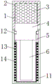
Fig. 1 is a sectional view of the whole structure of the shock absorption protection device for the automatic comprehensive wire inspection device provided by the utility model;
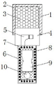
fig. 2 is a sectional view of a first protection shell structure of the shock absorption protection device for the automatic comprehensive wire inspection device provided by the utility model;
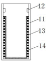
fig. 3 is a sectional view of a second protective casing of the shock absorption protection device for the automatic comprehensive wire inspection device provided by the utility model;
fig. 4 is the utility model provides an automatic change comprehensive inspection utensils shock attenuation protection device's overall structure elevation.
In the figure: 1 first protective housing, 2 reserve battery jars, 3 reserve batteries, 4 connecting blocks, 5 draw-in grooves, 6 place the shell, 7 first damping spring, 8 first foam-rubber cushion, 9 wire inspection ware mounting groove, 10 wire releasing grooves, 11 second protective housing, 12 fixture blocks, 13 second damping spring, 14 second foam-rubber cushion, 15 string knot.
Detailed Description
The technical solutions in the embodiments of the present invention will be described clearly and completely with reference to the accompanying drawings in the embodiments of the present invention, and it is obvious that the described embodiments are only some embodiments of the present invention, not all embodiments.
Referring to fig. 1-4, a shock absorption protection device for an automatic comprehensive wire tester comprises a first protection shell 1 and a second protection shell 14, wherein a standby battery groove 2 is arranged in the first protection shell 1, a standby battery 3 is inserted into the inner wall of the standby battery groove 2, the inner wall of the bottom of the first protection shell 1 is provided with screw threads, a connecting block 4 is screwed on the inner wall of the bottom of the first protection shell 1, two sides of the outer wall of the connecting block 4 are respectively provided with a clamping groove 5, the clamping grooves 5 are in an L-shaped structure, a baffle is adhered on the inner wall of the middle part of each clamping groove 5, a placing shell 6 is adhered on the outer wall of the bottom of each connecting block 4, first shock absorption springs 7 are welded on the inner wall of each placing shell 6 at equal intervals, one ends, far away from the placing shell 6, of the first shock absorption springs 7 are respectively adhered with a first sponge pad 8, a wire tester placing groove 9 and a wire releasing groove 10 are arranged on the top of each first, the fixture block 12 is bonded on two sides of the inner wall of the top of the second protective shell 11, the first protective shell 1 and the second protective shell 11 are connected through the clamping groove 5 and the fixture block 12 in a clamped mode to form, a sealing gasket is bonded on the joint of the first protective shell 1 and the second protective shell 11, the diameter of the fixture block 12 is matched with the inner diameter of the clamping groove 5, the fixture block 12 and the clamping groove 5 form sliding fit, second damping springs 13 are welded on the inner wall of the bottom of the second protective shell 11 at equal intervals, a second sponge pad 14 is bonded on one end, away from the second protective shell 11, of each second damping spring 13, plastic films are bonded on the outer walls of the first sponge pad 8 and the second sponge pad 14, a hanging buckle 15 is bonded on the outer wall of one side of the first protective shell 1, and.
The working principle is as follows: when the user uses this protection device, at first with first protective housing 1 in the rotatory part of connecting block 4, after filling in the inside reserve battery groove 2 of first protective housing 1 with fully charged stand-by battery 3, the spiro union is good connecting block 4, then place the inside back at cable finder resettlement groove 9 with the cable finder that needs to place, place the lines that need to use inside unwrapping wire groove 10 again, after placing and finishing, with the inside fixture block 12 of second protective housing 11 after aiming at draw-in groove 5 of connecting block 4 both sides, rotatory second protective housing 11 is complete with first protective housing 1 and the concatenation of second protective housing 11, later hang buckle 15 and hand-carry on user's belt, when going out to use cable finder no electricity, take out stand-by battery 3 in the reserve groove 2 and change it inside the cable finder, make cable finder continue to work.
The above, only be the concrete implementation of the preferred embodiment of the present invention, but the protection scope of the present invention is not limited thereto, and any person skilled in the art is in the technical scope of the present invention, according to the technical solution of the present invention and the utility model, the concept of which is equivalent to replace or change, should be covered within the protection scope of the present invention.
Claims (7)
1. The shock absorption protection device for the automatic comprehensive wire checker comprises a first protection shell (1) and a second protection shell (11), and is characterized in that a standby battery groove (2) is arranged inside the first protection shell (1), a standby battery (3) is inserted into the inner wall of the standby battery groove (2), threads are arranged on the inner wall of the bottom of the first protection shell (1), a connecting block (4) is screwed on the inner wall of the bottom of the first protection shell (1), clamping grooves (5) are arranged on two sides of the outer wall of the connecting block (4), a placing shell (6) is bonded on the outer wall of the bottom of the connecting block (4), first shock absorption springs (7) are welded on the inner wall of the placing shell (6) at equal intervals, first sponge cushions (8) are bonded on one ends, far away from the placing shell (6), of the first sponge cushions (7), a wire checker placing groove (9) and a paying-off groove (10) are arranged at the top of the first sponge cushions (8), the utility model discloses a damping device, including first protective housing (1), second protective housing (11) top inner wall both sides all bond and have fixture block (12), and second protective housing (11) bottom inner wall equidistance welding has second damping spring (13), second damping spring (13) keep away from the one end of second protective housing (11) and all bond and have second foam-rubber cushion (14), first protective housing (1) one side outer wall bonds and has hang knot (15).
2. The shock absorption protection device for the automatic comprehensive cable inspection device as claimed in claim 1, wherein plastic films are adhered to the outer walls of the first spongy cushion (8) and the second spongy cushion (14).
3. The shock absorption protection device for the automatic comprehensive wire inspector according to claim 1, wherein the diameter of the fixture block (12) is adapted to the inner diameter of the fixture groove (5), and the fixture block (12) and the fixture groove (5) form a sliding fit.
4. The automatic change and synthesize shock attenuation protection device for wire inspection ware of claim 1, characterized in that, first protective housing (1) and second protective housing (11) are formed through draw-in groove (5) and fixture block (12) joint, and the junction of first protective housing (1) and second protective housing (11) bonds there is the sealed pad.
5. The shock absorption protection device for the automatic comprehensive wire tester as claimed in claim 1, wherein the hanging buckle (15) is made of elastic plastic.
6. The shock absorption protection device for the automatic comprehensive wire checker according to claim 1, wherein the wire checker placing groove (9) is adapted to the wire checker, and the wire releasing groove (10) is adapted to the wire.
7. The shock absorption protection device for the automatic comprehensive wire inspection device as claimed in claim 1, wherein the slot (5) is of an L-shaped structure, and a stop bar is bonded to the inner wall of the middle part of the slot (5).
Priority Applications (1)
| Application Number | Priority Date | Filing Date | Title |
|---|---|---|---|
| CN201921780535.XU CN210637441U (en) | 2019-10-23 | 2019-10-23 | Automatic change comprehensive inspection line utensils shock attenuation protection device |
Applications Claiming Priority (1)
| Application Number | Priority Date | Filing Date | Title |
|---|---|---|---|
| CN201921780535.XU CN210637441U (en) | 2019-10-23 | 2019-10-23 | Automatic change comprehensive inspection line utensils shock attenuation protection device |
Publications (1)
| Publication Number | Publication Date |
|---|---|
| CN210637441U true CN210637441U (en) | 2020-05-29 |
Family
ID=70797460
Family Applications (1)
| Application Number | Title | Priority Date | Filing Date |
|---|---|---|---|
| CN201921780535.XU Active CN210637441U (en) | 2019-10-23 | 2019-10-23 | Automatic change comprehensive inspection line utensils shock attenuation protection device |
Country Status (1)
| Country | Link |
|---|---|
| CN (1) | CN210637441U (en) |
-
2019
- 2019-10-23 CN CN201921780535.XU patent/CN210637441U/en active Active
Similar Documents
| Publication | Publication Date | Title |
|---|---|---|
| CN107946845B (en) | Power communication coaxial cable connects fixing device | |
| CN210637441U (en) | Automatic change comprehensive inspection line utensils shock attenuation protection device | |
| CN208239480U (en) | A kind of multifunctional lithium ion cell test fixture | |
| CN207268764U (en) | A kind of electric power cable fault test set | |
| CN210578525U (en) | Outdoor interphone | |
| CN212909950U (en) | Portable charging device for Bluetooth headset | |
| CN207020233U (en) | A kind of damp-proof household electric electricity box | |
| CN114839566A (en) | Multifunctional electrical equipment detection device for cigarette factory | |
| CN209896385U (en) | Adapter with power line built-in function | |
| CN210073962U (en) | Battery pack device | |
| CN210142996U (en) | Photovoltaic module test equipment | |
| CN214150990U (en) | Low-cost voltage isolation detection device | |
| CN212721775U (en) | Novel non-contact forehead temperature gun | |
| CN208239574U (en) | A kind of common rectifier diode detection device | |
| CN213093629U (en) | Dynamic reactive power compensation device | |
| CN218099254U (en) | Ammeter investigation appearance of visiting one's family after another with dustproof function | |
| CN210668840U (en) | High-speed automobile connector | |
| CN216486777U (en) | Bluetooth voice remote controller convenient to place | |
| CN217607509U (en) | Can accomodate multi-functional portable treasured that charges of data line | |
| CN209125779U (en) | A kind of electric brake test and maintenance device | |
| CN216577781U (en) | Toolbox is used in maintenance of electronic railway connecting net of being convenient for | |
| CN210273508U (en) | Low-voltage alternating-current reactive power compensation cabinet | |
| CN211669223U (en) | High-voltage junction box comprehensive tester | |
| CN218068264U (en) | Terminal function interface tester for electric power meter | |
| CN214481650U (en) | Optical module external member with protective structure |
Legal Events
| Date | Code | Title | Description |
|---|---|---|---|
| GR01 | Patent grant | ||
| GR01 | Patent grant |