CN210632449U - Batching sieving mechanism is used in classified screening concrete processing - Google Patents
Batching sieving mechanism is used in classified screening concrete processing Download PDFInfo
- Publication number
- CN210632449U CN210632449U CN201921259734.6U CN201921259734U CN210632449U CN 210632449 U CN210632449 U CN 210632449U CN 201921259734 U CN201921259734 U CN 201921259734U CN 210632449 U CN210632449 U CN 210632449U
- Authority
- CN
- China
- Prior art keywords
- frame
- batching
- plate
- limiting plate
- concrete processing
- Prior art date
- Legal status (The legal status is an assumption and is not a legal conclusion. Google has not performed a legal analysis and makes no representation as to the accuracy of the status listed.)
- Expired - Fee Related
Links
Images

Landscapes
- Combined Means For Separation Of Solids (AREA)
Abstract
The utility model discloses a screening concrete processing is with batching sieving mechanism in grades, which comprises a top plate, the middle part of roof is reserved there is the charge tank, it has the frame all closely to laminate in the left and right sides of going up the sieve, the locating lever is fixed on last sieve, the right side of frame closely laminates there is the rubber pad, the lug is installed in the left side of frame, the outside draw-in groove of connecting rod is connected with first limiting plate, the middle part integration of connecting rod is provided with the protection frame, the rear side welding of first limiting plate has the pillar, the guard plate has all been welded to both sides around going up the sieve, the upside draw-in groove of guard plate is connected with the dust guard. This classified screening is batching sieving mechanism for concrete processing can effectively divide into the size of difference with the batching, and easy to assemble and dismantlement, the unloading of being convenient for, effective vibration screening prevents that the batching from blockking up the sieve mesh, and work efficiency is high, and is effective spacing, and stability is strong, can play the guard action to the sieve bucket.
Description
Technical Field
The utility model relates to a concrete processing technology field specifically is a classified screening concrete processing is with batching sieving mechanism.
Background
The concrete processing is divided into multiple steps of proportioning, stirring, forming and the like, wherein the ingredients are required to be screened before proportioning so as to screen out raw materials meeting the use regulation, and the quality of the ingredients plays a crucial role in the final forming effect of the concrete, so that the screening of the ingredients is significant for the concrete processing and manufacturing;
the concrete processing that uses at present is with batching sieving mechanism, inconvenient divide into different sizes with the batching, inconvenient installation and dismantlement, the unloading of being not convenient for, the batching blocks up the sieve mesh easily, work efficiency is high inadequately, and is inconvenient spacing, and stability is not strong enough, and is inconvenient to play the guard action to the sieve bucket, consequently, we propose a grading screening concrete processing with batching sieving mechanism to in solving the problem that proposes in the aforesaid.
SUMMERY OF THE UTILITY MODEL
An object of the utility model is to provide a screening concrete processing is with batching sieving mechanism in grades to solve the current screening concrete processing of batching sieving mechanism who proposes among the above-mentioned background art and inconvenient divide into the size of difference with the batching, inconvenient installation and dismantlement, the unloading of being not convenient for, the batching blocks up the sieve mesh easily, and work efficiency is high inadequately, and is inconvenient spacing, and stability is not strong enough, and is inconvenient to play the problem of guard action to the sieve bucket.
In order to achieve the above object, the utility model provides a following technical scheme: a batching and screening device for graded screening concrete processing comprises a top plate, wherein a feeding groove is reserved in the middle of the top plate, an upper sieve plate is arranged on the lower side of the feeding groove, connecting blocks are connected to the left side and the right side of the inner portion of the top plate in a sliding manner, frames are tightly attached to the left side and the right side of the upper sieve plate, a positioning rod is connected to the inner portion of each frame in a penetrating manner, the positioning rod is fixed on the upper sieve plate, a bottom sieve plate is arranged on the lower side of the upper sieve plate, a rubber pad is tightly attached to the right side of each frame, a first spring is connected to the right side of the rubber pad in a sticking manner, a convex block is installed on the left side of each frame, a connecting rod is fixedly connected to the left side of each convex block, a first limiting plate is connected to an outer clamping groove of the connecting rod, and the inboard bottom swing joint of pillar has the groove of accepting, the guard plate has all been welded to both sides around going up the sieve, the dead lever is all installed to both sides around the locating lever, and the outside of dead lever closely laminates and has the second limiting plate, the upside draw-in groove of guard plate is connected with the dust guard.
Preferably, the upper sieve plate forms a zigzag structure on the frame, the frame and the connecting block form an integrated structure, and the length of the cross section of the upper side of the connecting block is greater than that of the cross section of the lower side of the connecting block.
Preferably, the eccentric wheel is connected with the protective frame in a clamping groove connection mode, the protective frame is arranged on the supporting column at equal intervals, and the protective frame and the first springs are arranged in a one-to-one correspondence mode.
Preferably, the connecting rod forms a sliding structure in the first limiting plate, and the cross section of the first limiting plate is of an n-shaped structure.
Preferably, the second limiting plate constitutes the dismantlement structure on the dead lever, and the second limiting plate constitutes elevation structure in the frame to the longitudinal section of second limiting plate is "L" font structure, and the outside protrusion of second limiting plate sets up in the surface of frame moreover.
Preferably, the positioning rods are symmetrically arranged about a vertical central axis of the upper sieve plate, and the positioning rods form a disassembly structure in the frame.
Compared with the prior art, the beneficial effects of the utility model are that: the batching screening device for classified screening concrete processing can effectively divide batching into different sizes, is convenient to install and disassemble, is convenient to discharge, can effectively screen in a vibrating manner, prevents the batching from blocking sieve pores, has high working efficiency, is effective in limiting, has strong stability, and can protect a sieve barrel;
1. the upper sieve plate, the bottom sieve plate and the bearing grooves are arranged, ingredients can be effectively divided into different sizes on the upper sieve plate which forms a zigzag structure in the frame, the second limiting plate slides upwards, then the upper sieve plate is pulled outwards, and the positioning rod slides in the frame, so that the installation and the disassembly are convenient, and the blanking is convenient;
2. the device is provided with a pillar, an eccentric wheel and a protective frame, the eccentric wheel rotates on the pillar, the eccentric wheel drives the protective frame connected with an outer side clamping groove to slide, a lug arranged on the right side of a connecting rod pushes a frame to the right side, a rubber pad and a first spring which are arranged in one-to-one correspondence with the protective frame rebound the frame, the frame is effectively screened in a vibration mode, a first limiting plate which is perpendicular to an upper sieve plate pushes the upper sieve plate to the left and the right, the material is prevented from blocking sieve pores, and the working efficiency is high;
3. be provided with first limiting plate, locating lever and rubber pad, the connecting rod through the installation of protective frame both sides slides in first limiting plate, goes up the locating lever and the frame draw-in groove of installation on the sieve and is connected, and is effective spacing, and stability is strong, through equidistant rubber pad and the lug that sets up, can play the guard action to the sieve bucket.
Drawings
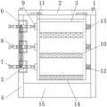
Fig. 1 is a schematic view of the front cross-sectional structure of the present invention;
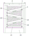
FIG. 2 is a schematic side view of the cross-sectional structure of the present invention;
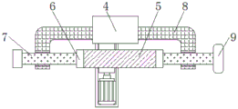
fig. 3 is a schematic view of the connection overlooking cross-sectional structure of the connection rod and the first limiting plate of the present invention;
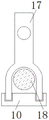
FIG. 4 is a schematic view of the connection structure of the positioning rod and the frame of the present invention;
fig. 5 is the utility model discloses second limiting plate and dead lever are connected and are looked sideways at the structural schematic diagram.
In the figure: 1. a top plate; 2. a feed tank; 3. an upper sieve plate; 4. a pillar; 5. an eccentric wheel; 6. a protective frame; 7. a connecting rod; 8. a first limit plate; 9. a bump; 10. a frame; 11. connecting blocks; 12. a rubber pad; 13. a first spring; 14. a bottom sieve plate; 15. a receiving groove; 16. a protection plate; 17. a second limiting plate; 18. fixing the rod; 19. positioning a rod; 20. a dust guard.
Detailed Description
The technical solutions in the embodiments of the present invention will be described clearly and completely with reference to the accompanying drawings in the embodiments of the present invention, and it is obvious that the described embodiments are only some embodiments of the present invention, not all embodiments. Based on the embodiments in the present invention, all other embodiments obtained by a person skilled in the art without creative work belong to the protection scope of the present invention.
Referring to fig. 1-5, the present invention provides a technical solution: a batching and screening device for processing graded screening concrete comprises a top plate 1, a feeding tank 2, an upper sieve plate 3, a support column 4, an eccentric wheel 5, a protective frame 6, a connecting rod 7, a first limiting plate 8, a lug 9, a frame 10, a connecting block 11, a rubber pad 12, a first spring 13, a bottom sieve plate 14, a receiving tank 15, a protective plate 16, a second limiting plate 17, a fixing rod 18, a positioning rod 19 and a dustproof plate 20, wherein the feeding tank 2 is reserved in the middle of the top plate 1, the upper sieve plate 3 is arranged on the lower side of the feeding tank 2, the connecting block 11 is connected to the left side and the right side of the inside of the top plate 1 in a sliding manner, the frames 10 are tightly attached to the left side and the right side of the upper sieve plate 3, the positioning rod 19 is connected to the inside of the frames 10 in a penetrating manner, the positioning rod 19 is fixed on the upper sieve plate 3, the bottom sieve plate 14 is arranged on the lower side of, lug 9 is installed in the left side of frame 10, and the left side fixedly connected with connecting rod 7 of lug 9, the outside draw-in groove of connecting rod 7 is connected with first limiting plate 8, the middle part integration of connecting rod 7 is provided with protecting frame 6, and the inside of protecting frame 6 is rotated and is connected with eccentric wheel 5, the rear side welding of first limiting plate 8 has pillar 4, and the inboard bottom swing joint of pillar 4 has the groove 15 of accepting, guard plate 16 has all been welded to both sides around going up sieve plate 3, dead lever 18 is all installed to both sides around locating lever 19, and the outside of dead lever 18 closely laminates and has second limiting plate 17, the upside draw-in groove of guard plate 16 is connected with dust guard 20.
As shown in fig. 1 and 2, the upper sieve plate 3 forms a zigzag structure on the frame 10, the frame 10 and the connecting block 11 form an integrated structure, and the length of the cross section of the upper side of the connecting block 11 is greater than that of the cross section of the lower side, so that classified screening is realized, and blanking is facilitated, as shown in fig. 1, the eccentric wheel 5 and the protective frame 6 are connected in a clamping groove connection mode, the protective frames 6 are arranged on the support post 4 at equal intervals, the protective frames 6 and the first springs 13 are arranged in a one-to-one correspondence manner, so that the screening effect is good, the frame 10 can be protected, as shown in fig. 3, the connecting rod 7 forms a sliding structure in the first limiting plate 8, the cross section of the first limiting plate 8 is in an n-shaped structure, the connecting;
constitute the dismantlement structure on dead lever 18 as second limiting plate 17 in fig. 4, and second limiting plate 17 constitutes elevation structure in frame 10, and the longitudinal section of second limiting plate 17 is "L" font structure, and the outside protrusion of second limiting plate 17 sets up in the surface of frame 10, conveniently adjust the position of second limiting plate 17, convenient to detach, locating lever 19 sets up about the vertical axis symmetry of last sieve 3 in fig. 5, and locating lever 19 constitutes the dismantlement structure in frame 10, easy to assemble and dismantlement, it is effective spacing.
The working principle is as follows: when the batching and screening device for graded screening concrete processing is used, firstly, as shown in an attached drawing 1, batching is poured onto an upper screen plate 3 from a feeding groove 2 reserved on a top plate 1, then a motor is turned on, as shown in the upper screen plate 3 of the attached drawing, the motor drives an eccentric wheel 5 to rotate on a support column 4, the eccentric wheel 5 drives a protective frame 6 connected with an outer side clamping groove to slide, connecting rods 7 arranged at two sides of the protective frame 6 slide in first limiting plates 8, a convex block 9 arranged at the right side of the connecting rod 7 is tightly attached to a frame 10, the frame 10 is pushed to the right side, rubber pads 12 and first springs 13 which are arranged in one-to-one correspondence with the protective frame 6 rebound the frame 10, as shown in the attached drawing 2, the batching is graded and screened by the upper screen plate 3 in a zigzag structure in the frame 10, blockage can be prevented, the screened bottommost batching falls into a receiving groove 15 from a bottom screen plate 14, and, the dustproof plate 20 can effectively prevent dust, and the protective plate 16 can prevent ingredients from falling;
after the screening is completed, as shown in fig. 4 and fig. 5, the second limiting plate 17 is slid upwards to separate the second limiting plate 17 from being connected with the clamping groove of the fixing rod 18, the upper screen plate 3 is pulled outwards to separate the protection plate 16 mounted on the upper screen plate 3 from being connected with the clamping groove of the dust-proof plate 20, the positioning rod 19 slides in the frame 10, and then the ingredients on the upper screen plate 3 are poured out, so that a series of operations of the ingredient screening device for processing graded screening concrete are completed.
The utility model discloses the standard part that uses all can purchase from the market, and dysmorphism piece all can be customized according to the description with the record of drawing of description, and the concrete connection mode of each part all adopts conventional means such as ripe bolt, rivet, welding among the prior art, and machinery, part and equipment all adopt prior art, and conventional model, including circuit connection adopts conventional connection mode among the prior art, does not detailed here again.
Although the present invention has been described in detail with reference to the foregoing embodiments, it will be apparent to those skilled in the art that modifications may be made to the embodiments or portions thereof without departing from the spirit and scope of the invention.
Claims (6)
1. The utility model provides a classified screening concrete processing is with batching sieving mechanism, includes roof (1), its characterized in that: the middle part of the top plate (1) is reserved with a feeding tank (2), an upper sieve plate (3) is arranged on the lower side of the feeding tank (2), connecting blocks (11) are connected to the left side and the right side of the inside of the top plate (1) in a sliding mode, frames (10) are tightly attached to the left side and the right side of the upper sieve plate (3), a positioning rod (19) is connected to the inside of each frame (10) in a penetrating mode, the positioning rod (19) is fixed to the upper sieve plate (3), a bottom sieve plate (14) is arranged on the lower side of the upper sieve plate (3), a rubber pad (12) is tightly attached to the right side of each frame (10), a first spring (13) is connected to the right side of each rubber pad (12) in a sticking mode, a convex block (9) is installed on the left side of each frame (10), a connecting rod (7) is fixedly connected to, the middle part integration of connecting rod (7) is provided with protecting frame (6), and the inside rotation of protecting frame (6) is connected with eccentric wheel (5), the rear side welding of first limiting plate (8) has pillar (4), and the inboard bottom swing joint of pillar (4) has and accepts groove (15), guard plate (16) have all been welded to both sides around going up sieve (3), dead lever (18) are all installed to both sides around locating lever (19), and the outside of dead lever (18) closely laminate and have second limiting plate (17), the upside draw-in groove of guard plate (16) is connected with dust guard (20).
2. The batching and screening device for graded screening concrete processing according to claim 1, characterized in that: go up sieve (3) and constitute zigzag structure on frame (10), and frame (10) and connecting block (11) constitute integrated configuration to the upside cross section length of connecting block (11) is greater than downside cross section length.
3. The batching and screening device for graded screening concrete processing according to claim 1, characterized in that: the eccentric wheel (5) is connected with the protective frame (6) in a clamping groove connection mode, the protective frame (6) is arranged on the supporting column (4) at equal intervals, and the protective frame (6) and the first springs (13) are arranged in a one-to-one correspondence mode.
4. The batching and screening device for graded screening concrete processing according to claim 1, characterized in that: the connecting rod (7) forms a sliding structure in the first limiting plate (8), and the cross section of the first limiting plate (8) is of an n-shaped structure.
5. The batching and screening device for graded screening concrete processing according to claim 1, characterized in that: the second limiting plate (17) forms a dismounting structure on the fixing rod (18), the second limiting plate (17) forms a lifting structure in the frame (10), the longitudinal section of the second limiting plate (17) is of an L-shaped structure, and the outer side of the second limiting plate (17) protrudes out of the outer surface of the frame (10).
6. The batching and screening device for graded screening concrete processing according to claim 1, characterized in that: the positioning rods (19) are symmetrically arranged about a vertical central axis of the upper sieve plate (3), and the positioning rods (19) form a disassembly structure in the frame (10).
Priority Applications (1)
| Application Number | Priority Date | Filing Date | Title |
|---|---|---|---|
| CN201921259734.6U CN210632449U (en) | 2019-08-06 | 2019-08-06 | Batching sieving mechanism is used in classified screening concrete processing |
Applications Claiming Priority (1)
| Application Number | Priority Date | Filing Date | Title |
|---|---|---|---|
| CN201921259734.6U CN210632449U (en) | 2019-08-06 | 2019-08-06 | Batching sieving mechanism is used in classified screening concrete processing |
Publications (1)
| Publication Number | Publication Date |
|---|---|
| CN210632449U true CN210632449U (en) | 2020-05-29 |
Family
ID=70801072
Family Applications (1)
| Application Number | Title | Priority Date | Filing Date |
|---|---|---|---|
| CN201921259734.6U Expired - Fee Related CN210632449U (en) | 2019-08-06 | 2019-08-06 | Batching sieving mechanism is used in classified screening concrete processing |
Country Status (1)
| Country | Link |
|---|---|
| CN (1) | CN210632449U (en) |
-
2019
- 2019-08-06 CN CN201921259734.6U patent/CN210632449U/en not_active Expired - Fee Related
Similar Documents
| Publication | Publication Date | Title |
|---|---|---|
| CN210632449U (en) | Batching sieving mechanism is used in classified screening concrete processing | |
| CN218854818U (en) | Screening equipment | |
| CN216093911U (en) | A broken mechanism for coal cinder | |
| CN217451442U (en) | Concrete crushing and recycling equipment for constructional engineering | |
| CN205096083U (en) | Sand sieving mechanism | |
| CN211838999U (en) | Sand sieving mechanism for highway construction | |
| CN210753698U (en) | Impurity cleaning device is used in processing of silica micropowder | |
| CN211463259U (en) | Fine miropowder graphite grinding device of high purity | |
| CN210546318U (en) | Shale shaker for civil engineering | |
| CN209935220U (en) | Rice hull screening plant is used in rice processing production | |
| CN208116150U (en) | A kind of multilayer rubble vibrating screen material device | |
| CN217616003U (en) | Raw and other materials screen frame that sieves | |
| CN211636743U (en) | Grinding apparatus production of effective screening is with binder raw materials reducing mechanism | |
| CN219765950U (en) | Quick screening mechanism of ground rice raw materials | |
| CN215918167U (en) | Particle sieving device for preparing azithromycin tablets | |
| CN212856124U (en) | Dolomite crusher with dust suppression function | |
| CN215940566U (en) | Flour processing apparatus with edulcoration function | |
| CN218138687U (en) | Wood chip collecting device for furniture production equipment | |
| CN210965403U (en) | Biomass fuel breaker of convenient unloading | |
| CN219092231U (en) | Hydroxypropyl starch grinds processing equipment | |
| CN213612560U (en) | Automatic ore optimization equipment | |
| CN210333299U (en) | Vibrating screen for screening metal powder | |
| CN218251474U (en) | Raw materials screening plant is used in concrete production | |
| CN220559767U (en) | Grain purchasing screening machine with adjustable height | |
| CN217120808U (en) | Dehydrated vegetable screening and processing device |
Legal Events
| Date | Code | Title | Description |
|---|---|---|---|
| GR01 | Patent grant | ||
| GR01 | Patent grant | ||
| CF01 | Termination of patent right due to non-payment of annual fee |
Granted publication date: 20200529 |
|
| CF01 | Termination of patent right due to non-payment of annual fee |