CN210630097U - Mounting structure of charging chip module in storage battery - Google Patents
Mounting structure of charging chip module in storage battery Download PDFInfo
- Publication number
- CN210630097U CN210630097U CN201921790778.1U CN201921790778U CN210630097U CN 210630097 U CN210630097 U CN 210630097U CN 201921790778 U CN201921790778 U CN 201921790778U CN 210630097 U CN210630097 U CN 210630097U
- Authority
- CN
- China
- Prior art keywords
- protective housing
- storage battery
- chip
- spring
- mounting structure
- Prior art date
- Legal status (The legal status is an assumption and is not a legal conclusion. Google has not performed a legal analysis and makes no representation as to the accuracy of the status listed.)
- Expired - Fee Related
Links
- 230000001681 protective effect Effects 0.000 claims abstract description 60
- 238000013016 damping Methods 0.000 claims abstract description 15
- 239000002184 metal Substances 0.000 claims abstract description 9
- 239000004745 nonwoven fabric Substances 0.000 claims abstract description 8
- VYPSYNLAJGMNEJ-UHFFFAOYSA-N Silicium dioxide Chemical compound O=[Si]=O VYPSYNLAJGMNEJ-UHFFFAOYSA-N 0.000 claims abstract description 6
- 239000000741 silica gel Substances 0.000 claims abstract description 6
- 229910002027 silica gel Inorganic materials 0.000 claims abstract description 6
- 238000012856 packing Methods 0.000 claims 1
- 230000001739 rebound effect Effects 0.000 abstract description 4
- 238000012423 maintenance Methods 0.000 abstract description 3
- 230000008859 change Effects 0.000 abstract description 2
- 230000002349 favourable effect Effects 0.000 abstract description 2
- 238000010521 absorption reaction Methods 0.000 description 4
- 239000002253 acid Substances 0.000 description 4
- 230000035939 shock Effects 0.000 description 4
- 230000004048 modification Effects 0.000 description 2
- 238000012986 modification Methods 0.000 description 2
- 238000003756 stirring Methods 0.000 description 2
- 230000009471 action Effects 0.000 description 1
- 230000007547 defect Effects 0.000 description 1
- 230000000694 effects Effects 0.000 description 1
- 230000006872 improvement Effects 0.000 description 1
- 238000009434 installation Methods 0.000 description 1
- 230000007774 longterm Effects 0.000 description 1
- 239000002243 precursor Substances 0.000 description 1
Images


Landscapes
- Battery Mounting, Suspending (AREA)
Abstract
The utility model discloses a mounting structure of chip module that charges in storage battery, including storage battery protective housing, first spring, slider, non-woven fabric net, silica gel hygroscopic layer, chip protective housing, first hinge, chip visor, spacing fixed block, chip circuit board, storage battery visor, second hinge, damping spring, arc metal flexure strip, telescopic link, bottom plate, rectangle set casing, second spring, plectrum, inserted bar and second slider. The utility model has the advantages that: this device carries out fixed mounting to the chip circuit board through the chip protective housing, does not need instrument and mounting during fixed mounting, and is comparatively convenient and fast, is favorable to the change and the maintenance work of chip circuit board, when dismantling the chip protective housing, makes the chip protective housing pop out from the inner chamber of storage battery protective housing through the rebound effect of first spring, further makes things convenient for the work of taking out of chip protective housing.
Description
Technical Field
The utility model relates to a mounting structure specifically is a mounting structure of charging chip module in storage battery belongs to charging chip module mounting structure application technical field.
Background
The battery of the electric vehicle is a power source on the electric vehicle, most of the existing electric vehicles are provided with lead-acid storage batteries, and the lead-acid storage batteries have low cost and high cost performance. Since this battery can be charged and used repeatedly, it is called "lead-acid battery", in 1860, pulanta, france invented a battery using lead as electrode, which is the precursor of lead-acid battery.
The storage battery at present stage charges and all uses charging chip to control the charge-discharge for charge-discharge safe and reliable more, but charging chip on the storage battery car leads to charging chip to place at the open air with the storage battery car together basically because of the use of storage battery car, consequently charging chip easily wets and breaks down, the use of storage battery car leads to charging chip to be in the shock condition for a long time simultaneously, be unfavorable for charging chip's saving, charging chip need use instruments such as screwdriver and screw when changing the maintenance, it is comparatively troublesome to dismantle the installation. Therefore, the mounting structure of the charging chip module in the battery cell is provided for solving the problems.
SUMMERY OF THE UTILITY MODEL
The to-be-solved technical problem of the utility model is to overcome prior art's defect, provide a mounting structure of charging chip module in the storage battery.
In order to solve the technical problem, the utility model provides a following technical scheme:
the utility model relates to a mounting structure of a charging chip module in a battery jar, which comprises a battery jar protective shell, a chip protective shell and a damping structure, wherein the inner wall of the cavity of the battery jar protective shell is fixedly connected with one end of a first spring, the other end of the first spring is fixedly connected with a slide block, the cavity of the battery jar protective shell is slidably connected with the chip protective shell, the upper surface of the chip protective shell is fixedly connected with a limiting fixed block, the surface side wall of the battery jar protective shell is fixedly connected with a rectangular fixed shell, the inner cavity of the rectangular fixed shell is slidably connected with a second slide block, one end of the second slide block is fixedly connected with one end of a second spring, the other end of the second spring is fixedly connected to the inner cavity side wall of the rectangular fixed shell, the other end of the second slide block is fixedly connected with one end of an inserted bar, the other end of the inserted bar penetrates through the, and a damping structure is fixedly arranged on the lower surface of the storage battery protective shell.
Preferably, shock-absorbing structure includes damping spring, arc metal elastic sheet, telescopic link and bottom plate, the bottom plate is total two, two connect through two telescopic links between the bottom plate, two fixedly connected with damping spring and two arc metal elastic sheets between the bottom plate.
Preferably, the damping structures are five in number and are respectively fixed at four corners and the central position of the lower surface of the storage battery protective shell.
Preferably, a chip circuit board is fixedly mounted in an inner cavity of the chip protection shell, the inner cavity walls on two sides of the chip protection shell are fixedly connected with non-woven fabric nets, and a silica gel moisture absorption layer is filled in the non-woven fabric nets.
Preferably, the limiting fixing block is provided with an opening which is the same as the inserting rod in size and shape.
Preferably, the outer surfaces of the storage battery protective shell and the rectangular fixed shell are respectively and fixedly connected with a second hinge and a first hinge, and the second hinge and the first hinge are respectively and rotatably connected with a chip protective cover and a storage battery protective cover.
The utility model has the advantages that:
this device carries out fixed mounting to the chip circuit board through the chip protective housing, does not need instrument and mounting during fixed mounting, and comparatively convenient and fast is favorable to the change and the maintenance work of chip circuit board, when dismantling the chip protective housing, makes the chip protective housing pop out from the inner chamber of storage battery protective housing through the rebound effect of first spring, further makes things convenient for the work of taking out of chip protective housing.
2 this device dehumidifies through the silica gel hygroscopic layer in the chip protective housing to the air of chip protective housing, prevent that components and parts on the inside chip circuit board from producing the trouble because of the humidity, the life of components and parts has been improved, prevent through shock-absorbing structure that storage battery protective housing and the inside storage battery of chip protective housing and chip circuit board from producing the trouble because of long-term vibrations, shock-absorbing structure makes the shock attenuation effect better through arc metal flexure strip and damping spring's combined action simultaneously, also make shock-absorbing structure's life longer.
Drawings
The accompanying drawings are included to provide a further understanding of the invention, and are incorporated in and constitute a part of this specification, illustrate embodiments of the invention, and together with the description serve to explain the invention and not to limit the invention.
In the drawings:
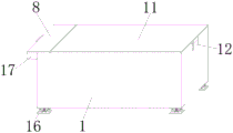
FIG. 1 is a schematic perspective view of the present invention;
FIG. 2 is a schematic view of the internal structure of the present invention;
fig. 3 is a schematic view of a partial enlarged structure at a in fig. 2 according to the present invention;
fig. 4 is a schematic view of a partial enlarged structure at a in fig. 2 according to the present invention;
fig. 5 is a schematic view of the three-dimensional structure of the shock-absorbing structure of the present invention.
In the figure: 1. storage battery protective housing, 2, first spring, 3, slider, 4, non-woven fabrics net, 5, silica gel hygroscopic layer, 6, chip protective housing, 7, first hinge, 8, chip visor, 9, spacing fixed block, 10, chip circuit board, 11, storage battery visor, 12, second hinge, 13, damping spring, 14, arc metal flexure strip, 15, telescopic link, 16, bottom plate, 17, rectangle set casing, 18, second spring, 19, plectrum, 20, inserted bar, 21, second slider.
Detailed Description
The preferred embodiments of the present invention will be described in conjunction with the accompanying drawings, and it will be understood that they are presented herein only to illustrate and explain the present invention, and not to limit the present invention.
Examples
As shown in figures 1 to 5, a mounting structure of a charging chip module in a storage battery comprises a storage battery protection shell 1, a chip protection shell 6 and a damping structure, wherein one end of a first spring 2 is fixedly connected to the inner wall of a cavity of the storage battery protection shell 1, a sliding block 3 is fixedly connected to the other end of the first spring 2, the chip protection shell 6 is slidably connected to the cavity of the storage battery protection shell 1, a limiting fixing block 9 is fixedly connected to the upper surface of the chip protection shell 6, a rectangular fixing shell 17 is fixedly connected to the surface side wall of the storage battery protection shell 1, a second sliding block 21 is slidably connected to the inner cavity of the rectangular fixing shell 17, one end of a second spring 18 is fixedly connected to one end of the second sliding block 21, the other end of the second spring 18 is fixedly connected to the inner cavity side wall of the rectangular fixing shell 17, and the other end of the second sliding block 21 is, the other end of inserted bar 20 runs through the fixed shell 17 of rectangle and the lateral wall of storage battery protective housing 1 and extends to in the inner chamber of storage battery protective housing 1, the fixed surface of storage battery protective housing 1 installs shock-absorbing structure.
The damping structure comprises two damping springs 13, two arc-shaped metal elastic sheets 14, two telescopic rods 15 and two bottom plates 16, the two bottom plates 16 are connected through the two telescopic rods 15, and the damping springs 13 and the two arc-shaped metal elastic sheets 14 are fixedly connected between the two bottom plates 16; the number of the shock absorption structures is five, and the shock absorption structures are respectively fixed at four corners and the central position of the lower surface of the storage battery protective shell 1; a chip circuit board 10 is fixedly arranged in an inner cavity of the chip protection shell 6, the inner cavity walls on two sides of the chip protection shell 6 are fixedly connected with non-woven fabric nets 4, and silica gel moisture absorption layers 5 are filled in the non-woven fabric nets 4; the limiting fixing block 9 is provided with an opening with the same size and shape as the inserting rod 20; the outer surfaces of the storage battery protective shell 1 and the rectangular fixed shell 17 are respectively fixedly connected with a second hinge 12 and a first hinge 7, and the second hinge 12 and the first hinge 7 are respectively connected with a chip protective cover 8 and a storage battery protective cover 11 in a rotating mode.
The utility model discloses when using, at first, when installing chip protective housing 6, stir earlier plectrum 19 and make plectrum 19 drive second slider 21 and remove, drive inserted bar 20 through second slider 21 and remove, then inject chip protective housing 6 in the inside cavity of storage battery protective housing 1, loosen plectrum 19, when chip protective housing 6 removes suitable position, rebound effect through second spring 18 makes inserted bar 20 inject in spacing fixed block 9, realize the fixed function to chip protective housing 6, when chip protective housing 6 needs to be dismantled, through stirring plectrum 19, make inserted bar 20 return and contract, when inserted bar 20 returns completely, rebound effect through first spring 2 makes chip protective housing 6 pop out from storage battery 1's cavity, convenient dismantlement.
Finally, it should be noted that: although the present invention has been described in detail with reference to the foregoing embodiments, it will be apparent to those skilled in the art that modifications may be made to the embodiments described in the foregoing embodiments, or equivalents may be substituted for elements thereof. Any modification, equivalent replacement, or improvement made within the spirit and principle of the present invention should be included in the protection scope of the present invention.
Claims (6)
1. The utility model provides a mounting structure of chip module that charges in storage battery which characterized in that: including storage battery protective housing (1), chip protective housing (6) and shock-absorbing structure, the one end of first spring (2) is connected with to the cavity inner wall fixed connection of storage battery protective housing (1), the other end fixed connection of first spring (2) has slider (3), sliding connection has chip protective housing (6) in the cavity of storage battery protective housing (1), the last fixed surface of chip protective housing (6) is connected with spacing fixed block (9), the surperficial lateral wall fixed connection of storage battery protective housing (1) has rectangle set shell (17), sliding connection has second slider (21) in the inner chamber of rectangle set shell (17), the one end fixed connection of second slider (21) has the one end of second spring (18), the other end fixed connection of second spring (18) is on the inner chamber lateral wall of rectangle set shell (17), the other end fixed connection of second slider (21) has the one end of inserted bar (20), the other end of inserted bar (20) runs through the lateral wall of the fixed shell of rectangle (17) and storage battery protective housing (1) and extends to the inner chamber of storage battery protective housing (1), the lower fixed surface of storage battery protective housing (1) installs shock-absorbing structure.
2. The mounting structure of the charging chip module in the battery jar as claimed in claim 1, wherein: shock-absorbing structure includes damping spring (13), arc metal elastic sheet (14), telescopic link (15) and bottom plate (16), bottom plate (16) are total two, two connect through two telescopic link (15) between bottom plate (16), two fixedly connected with damping spring (13) and two arc metal elastic sheet (14) between bottom plate (16).
3. The mounting structure of the charging chip module in the battery jar as claimed in claim 1, wherein: the damping structure is totally five and is respectively fixed at four corners and the center of the lower surface of the storage battery protective shell (1).
4. The mounting structure of the charging chip module in the battery jar as claimed in claim 1, wherein: fixed mounting has chip circuit board (10) in the inner chamber of chip protective housing (6), the equal fixedly connected with non-woven fabrics net (4) of both sides inner chamber wall of chip protective housing (6), the inside packing of non-woven fabrics net (4) has silica gel hygroscopic layer (5).
5. The mounting structure of the charging chip module in the battery jar as claimed in claim 1, wherein: the limiting fixing block (9) is provided with a hole which is the same as the inserted rod (20) in size and shape.
6. The mounting structure of the charging chip module in the battery jar as claimed in claim 1, wherein: the outer surface of the storage battery protective shell (1) and the outer surface of the rectangular fixed shell (17) are respectively fixedly connected with a second hinge (12) and a first hinge (7), and the second hinge (12) and the first hinge (7) are respectively rotatably connected with a chip protective cover (8) and a storage battery protective cover (11).
Priority Applications (1)
| Application Number | Priority Date | Filing Date | Title |
|---|---|---|---|
| CN201921790778.1U CN210630097U (en) | 2019-10-23 | 2019-10-23 | Mounting structure of charging chip module in storage battery |
Applications Claiming Priority (1)
| Application Number | Priority Date | Filing Date | Title |
|---|---|---|---|
| CN201921790778.1U CN210630097U (en) | 2019-10-23 | 2019-10-23 | Mounting structure of charging chip module in storage battery |
Publications (1)
| Publication Number | Publication Date |
|---|---|
| CN210630097U true CN210630097U (en) | 2020-05-26 |
Family
ID=70759766
Family Applications (1)
| Application Number | Title | Priority Date | Filing Date |
|---|---|---|---|
| CN201921790778.1U Expired - Fee Related CN210630097U (en) | 2019-10-23 | 2019-10-23 | Mounting structure of charging chip module in storage battery |
Country Status (1)
| Country | Link |
|---|---|
| CN (1) | CN210630097U (en) |
Cited By (1)
| Publication number | Priority date | Publication date | Assignee | Title |
|---|---|---|---|---|
| CN114435756A (en) * | 2022-01-24 | 2022-05-06 | 玉锡科技(苏州)有限公司 | Foam structure for shock absorption |
-
2019
- 2019-10-23 CN CN201921790778.1U patent/CN210630097U/en not_active Expired - Fee Related
Cited By (1)
| Publication number | Priority date | Publication date | Assignee | Title |
|---|---|---|---|---|
| CN114435756A (en) * | 2022-01-24 | 2022-05-06 | 玉锡科技(苏州)有限公司 | Foam structure for shock absorption |
Similar Documents
| Publication | Publication Date | Title |
|---|---|---|
| CN211139043U (en) | Battery installation box for new energy automobile | |
| CN112332000A (en) | Automobile battery pack installation device and new energy automobile's power storage device | |
| CN210630097U (en) | Mounting structure of charging chip module in storage battery | |
| CN108493366A (en) | Against shock lithium battery pack box body | |
| CN210778730U (en) | Lithium battery packaging shell | |
| CN113745723B (en) | New energy automobile battery box | |
| CN215008435U (en) | Be applied to new energy automobile's battery damping device | |
| CN209744322U (en) | LED drive power supply convenient to multiple environment uses | |
| CN213522843U (en) | Lithium battery protection plate with shock-absorbing function | |
| CN213937094U (en) | Explosion-proof distribution box | |
| CN210092164U (en) | Lithium battery pack for automobile | |
| CN209298670U (en) | A kind of power automation distribution box | |
| CN209981316U (en) | Lead carbon nano silica gel storage battery | |
| CN217881707U (en) | New energy battery shell with damping mechanism | |
| CN220290958U (en) | Lithium electricity shock attenuation casing | |
| CN215070206U (en) | Lithium battery shell | |
| CN218276626U (en) | Integrated energy storage solar cell | |
| CN219553794U (en) | Protective housing and lithium ion battery box | |
| CN221632740U (en) | Shock-absorbing lithium battery module | |
| CN218334039U (en) | Electric bicycle lithium battery mounting box with stable structure | |
| CN105280857A (en) | Battery box for electric vehicle | |
| CN215911519U (en) | New energy automobile battery fixing device | |
| CN220410276U (en) | New energy automobile chassis structure | |
| CN108819693A (en) | A kind of fixed device of battery group | |
| CN208714931U (en) | A kind of fixed device of battery group |
Legal Events
| Date | Code | Title | Description |
|---|---|---|---|
| GR01 | Patent grant | ||
| GR01 | Patent grant | ||
| CF01 | Termination of patent right due to non-payment of annual fee |
Granted publication date: 20200526 |
|
| CF01 | Termination of patent right due to non-payment of annual fee |