CN210620871U - Continuous energy-saving environment-friendly heat treatment device - Google Patents
Continuous energy-saving environment-friendly heat treatment device Download PDFInfo
- Publication number
- CN210620871U CN210620871U CN201921100512.XU CN201921100512U CN210620871U CN 210620871 U CN210620871 U CN 210620871U CN 201921100512 U CN201921100512 U CN 201921100512U CN 210620871 U CN210620871 U CN 210620871U
- Authority
- CN
- China
- Prior art keywords
- heat treatment
- box
- heat
- fixedly connected
- combustion
- Prior art date
- Legal status (The legal status is an assumption and is not a legal conclusion. Google has not performed a legal analysis and makes no representation as to the accuracy of the status listed.)
- Expired - Fee Related
Links
Images


Abstract
The utility model discloses a continuous energy-saving environment-friendly heat treatment device, which relates to the field of heat treatment equipment and comprises a heat treatment box, a front box cover, a rear box cover, a workpiece bracket, a combustion chamber, a regenerative utilization device, a support and a base, wherein the workpiece bracket is connected inside the heat treatment box; the upper end of the heat recovery utilization device is fixedly connected and communicated with the heat treatment box; the lower end of the heat recovery utilization device is fixedly connected with the outer ends of the three combustion chambers. The utility model discloses inside is equipped with three combustion chamber, can prevent that a combustion chamber can't carry out the problem of thermal treatment when breaking down, also can carry out thermal treatment to the work piece with the temperature of difference respectively.
Description
Technical Field
The utility model relates to a thermal treatment equipment field, more specifically the energy-concerving and environment-protective type heat treatment device of continuous type that says so.
Background
Heat treatment refers to a hot metal working process in which a material is heated, held and cooled in the solid state to achieve a desired texture and properties. In the process of moving from the times of stoneware to the times of cupreous and ironware, the effect of heat treatment is gradually recognized.
SUMMERY OF THE UTILITY MODEL
The utility model provides an energy-concerving and environment-protective type heat treatment device of continuous type, inside is equipped with three combustion chamber, can prevent that a combustion chamber can't carry out the problem of thermal treatment when breaking down, also can carry out thermal treatment to the work piece with the temperature of difference respectively.
In order to achieve the above purpose, the utility model discloses a following technical scheme realizes:
a continuous energy-saving environment-friendly heat treatment device comprises a heat treatment box, a front box cover, a rear box cover, a workpiece bracket, combustion chambers, a regenerative utilization device, a support and a base, wherein the workpiece bracket is connected inside the heat treatment box; the upper end of the heat recovery utilization device is fixedly connected and communicated with the heat treatment box; the lower end of the heat recovery utilization device is fixedly connected with the outer ends of the three combustion chambers.
And heat preservation and insulation boards are fixedly arranged on the outer box surface of the heat treatment box.
The front box cover comprises an electric push rod, a push-pull seat and a movable door; two electric push rods are arranged, and two ends of each electric push rod are fixedly connected with the right side surface of the heat treatment box and one end of the push-pull seat respectively; the other end of the push-pull seat is fixedly connected with one end of a movable door, and the movable door is in sealing sliding fit with the feed inlet of the heat treatment box.
The workpiece bracket comprises a servo motor, a motor base, a lead screw, a horizontal sliding block, a door-shaped frame and a workpiece supporting plate; the servo motor cylinder cover motor base is fixed on the heat treatment box; an output shaft of the servo motor is connected with a lead screw through a coupler, and two ends of the lead screw are respectively connected with the front end and the rear end of the heat treatment box in a sealing and rotating manner; the middle part of the lead screw is connected with a horizontal sliding block through threads; the top surface of the horizontal sliding block is in sliding fit with the top surface inside the heat treatment box; the bottom end of the horizontal sliding block is fixedly connected with the upper end of the door-shaped frame, and the lower end of the door-shaped frame is fixedly connected with the workpiece supporting plate.
The middle of the top surface of the workpiece supporting plate is provided with a workpiece supporting groove, and the bottom surface of the workpiece supporting groove is provided with a plurality of ventilation through holes in parallel.
The lower end of the interior of the combustion chamber is fixedly connected with a combustion-supporting air pipeline with an air suction fan, a coal injection machine and an igniter; and the combustion-supporting air pipeline is fixedly connected with the lower end of the regenerative utilization device.
The heat recovery utilization device comprises a heat recovery pipe with an exhaust fan, a heat exchange box and an exhaust pipe; two ends of the heat return pipe are respectively fixedly connected and communicated with the heat treatment box and the heat exchange box; the heat exchange box is fixedly connected to a combustion-supporting air pipeline, and a middle pipe body of the combustion-supporting air pipeline is positioned in the heat exchange box; the lower end of the heat exchange box is connected with an exhaust pipe through threads.
The combustion-supporting air pipeline is a copper pipe.
The utility model has the advantages that: the utility model is internally provided with three combustion chambers, which can respectively carry out heat treatment on the workpiece at different temperatures and prevent the problem that the heat treatment can not be carried out when one combustion chamber breaks down; the utility model discloses inside still is equipped with the backheat and utilizes the device that can retrieve the heat energy, utilizes the device to retrieve heat energy through backheat and can carry out the heat transfer to the air that is used for combustion-supporting, improves combustion-supporting effect, promotes heat treatment efficiency.
Drawings
The present invention will be described in further detail with reference to the accompanying drawings and specific embodiments.
Fig. 1 is a first schematic structural diagram of the present invention;
FIG. 2 is a second schematic structural view of the present invention;
FIG. 3 is a schematic view of the internal heat treatment chamber of the present invention;
FIG. 4 is a schematic structural view of the inner front case cover of the present invention;
FIG. 5 is a schematic structural view of the inner workpiece carrier of the present invention;
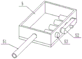
FIG. 6 is a schematic structural view of the internal combustion chamber of the present invention;
FIG. 7 is a schematic structural view of the internal regenerative heat utilization device of the present invention
In the figure: a heat treatment tank 1; a front case cover 2; an electric push rod 21; a push-pull seat 22; a movable door 23; a rear box cover 3; a workpiece carrier 4; a servo motor 41; a motor base 42; a lead screw 43; a horizontal slider 44; a door frame 45; a workpiece pallet 46; a combustion chamber 5; a combustion air duct 51; a coal injection machine 52; an igniter 53; a regenerative utilization device 6; a heat recovery pipe 61; a heat exchange tank 62; an exhaust pipe 63; a bracket 7; a base 8.
Detailed Description
The technical solutions in the embodiments of the present invention will be described clearly and completely with reference to the accompanying drawings in the embodiments of the present invention, and it is obvious that the described embodiments are only some embodiments of the present invention, not all embodiments. Based on the embodiments in the present invention, all other embodiments obtained by a person skilled in the art without creative work belong to the protection scope of the present invention.
The first embodiment is as follows:
referring to fig. 1-7, the present invention provides a technical solution:
a continuous energy-saving environment-friendly heat treatment device comprises a heat treatment box 1, a front box cover 2, a rear box cover 3, a workpiece bracket 4, combustion chambers 5, a regenerative utilization device 6, a support 7 and a base 8, wherein the workpiece bracket 4 is connected inside the heat treatment box 1, the front box cover 2 and the rear box cover 3 are respectively connected at a feed inlet and a discharge outlet of the heat treatment box 1, the front box cover 2 and the rear box cover 3 have the same structure, the three combustion chambers 5 are arranged side by side from front to back on the bottom surface of the heat treatment box 1, and the bottom end of the heat treatment box 1 is fixed on the base 8 through the front support 7 and the rear support 7; the upper end of the heat recovery utilization device 6 is fixedly connected and communicated with the heat treatment box 1; the lower end of the heat recovery utilization device 6 is fixedly connected with the outer ends of the three combustion chambers 5. The utility model discloses an energy-concerving and environment-protective type heat treatment device of continuous type, when needs carry out thermal treatment, the preceding case lid 2 of 1 front ends of control heat treatment case is opened at first, then place the work piece of pending at work piece bracket 4, then close preceding case lid 2, then transport the work piece to the upper end of combustion chamber 5 through the work piece bracket 4 that communicates the power, produce heat energy after the fuel burning of combustion chamber 5 inside and carry out thermal treatment to the work piece, combustion chamber 5 is equipped with threely, can carry out the heating of different degrees respectively, and then carry out the thermal treatment of different temperatures to the work piece, for example, can heat up in proper order from front to back, make the work piece can carry out appropriate preheating, be favorable to improving the thermal treatment effect of work piece; after heat treatment, opening the rear box cover 3, conveying the heat-treated workpiece to a discharge port of the heat treatment box 1 through the workpiece bracket 4, and performing subsequent treatment and cooling treatment after unloading; the heat energy generated in the heat treatment process of the workpiece can be collected through the heat recovery utilization device 6, and the air entering the combustion chamber 5 and used for supporting combustion is preheated through the heat recovery utilization device 6, so that the combustion heating effect is convenient to improve, and the heat treatment efficiency is further improved.
The second embodiment is as follows:
referring to fig. 1-7, the outer surface of the heat treatment box 1 is fixedly provided with heat insulation boards. The heat preservation heat insulating board adopts the board that has the thermal-insulated effect of heat preservation purchased on the market can for prevent that the inside heat energy of thermal treatment case 1 from running off, and prevent that the too high temperature of thermal treatment case 1 from scalding the workman.
The third concrete implementation mode:
referring to fig. 1-7, the front box cover 2 includes an electric push rod 21, a push-pull seat 22 and a movable door 23; two electric push rods 21 are arranged, and two ends of each electric push rod 21 are respectively fixedly connected with the right side surface of the heat treatment box 1 and one end of the push-pull seat 22; the other end of the push-pull seat 22 is fixedly connected with one end of a movable door 23, and the movable door 23 is in sealing sliding fit with a feed inlet of the heat treatment box 1. The front box cover 2 and the rear box cover 3 have the same structure and the same working principle; when the device is used, the electric push rod 21 is communicated with a power supply and then drives the movable door 23 to slide through the push-pull seat 22, so that the movable door 23 is blocked at the feed inlet of the heat treatment box 1 or separated from the feed inlet of the heat treatment box 1.
The fourth concrete implementation mode:
referring to fig. 1-7, the workpiece bracket 4 includes a servo motor 41, a motor base 42, a lead screw 43, a horizontal slider 44, a door-shaped frame 45 and a workpiece supporting plate 46; the cylinder cover motor seat 42 of the servo motor 41 is fixed on the heat treatment box 1; an output shaft of the servo motor 41 is connected with a lead screw 43 through a coupler, and two ends of the lead screw 43 are respectively connected with the front end and the rear end of the heat treatment box 1 in a sealing and rotating manner; the middle part of the lead screw 43 is connected with a horizontal sliding block 44 through threads; the top surface of the horizontal sliding block 44 is in sliding fit with the top surface inside the heat treatment box 1; the bottom end of the horizontal sliding block 44 is fixedly connected with the upper end of a door-shaped frame 45, and the lower end of the door-shaped frame 45 is fixedly connected with a workpiece supporting plate 46. The workpiece bracket 4 is used for supporting and placing a workpiece and moving the position of the workpiece, the servo motor 41 is powered on and can drive the lead screw 43 to rotate after being started, the lead screw 43 can drive the horizontal sliding block 44 to slide on the top surface inside the heat treatment box 1 when rotating, the horizontal sliding block 44 drives the workpiece bracket 46 to move through the portal frame 45 when sliding, and then the workpiece bracket 46 drives the workpiece to move.
The fifth concrete implementation mode:
referring to fig. 1-7, a workpiece supporting plate 46 has a supporting groove in the middle of its top surface, and a plurality of air holes are arranged in parallel on the bottom surface of the supporting groove. The setting in support groove can prevent that the work piece from falling, and the area of contact of work piece and hot-air is convenient for improve in the setting of a plurality of ventilative through-holes, and then improves heat treatment effect.
The sixth specific implementation mode:
referring to fig. 1 to 7, a combustion air duct 51 with an air suction fan, a coal injection machine 52 and an igniter 53 are fixedly connected to the lower end of the interior of the combustion chamber 5; the combustion-supporting air pipeline 51 is fixedly connected with the lower end of the regenerative utilization device 6. The coal injection machine 52 and the igniter 53 are both commercially available finished products, the coal injection machine 52 injects pulverized coal into the combustion chamber 5, the combustion air pipeline 51 inputs air into the combustion chamber 5, and the igniter 53 ignites to burn the pulverized coal, so as to heat the pulverized coal.
The seventh embodiment:
referring to fig. 1-7, the regenerative heat utilization device 6 includes a regenerative pipe 61 with an exhaust fan, a heat exchange box 62 and an exhaust pipe 63; two ends of the heat return pipe 61 are respectively fixedly connected and communicated with the heat treatment box 1 and the heat exchange box 62; the heat exchange box 62 is fixedly connected to the combustion air pipeline 51, and a middle pipe body of the combustion air pipeline 51 is positioned in the heat exchange box 62; the lower end of the heat exchange box 62 is connected with an exhaust pipe 63 through a screw thread.
The combustion air pipeline 51 is a copper pipe. The heat return pipe 61 with the exhaust fan pumps the heat-treated air into the heat exchange box 62, so that the air in the combustion air pipeline 51 is preheated and heat exchanged, and the combustion effect of the pulverized coal is improved; after heat exchange, the exhaust gas can be discharged into a corresponding heat exchanger or an exhaust gas treatment device through an exhaust pipe 63.
The working principle is as follows: the utility model discloses an energy-concerving and environment-protective type heat treatment device of continuous type, when needs carry out thermal treatment, the preceding case lid 2 of 1 front ends of control heat treatment case is opened at first, then place the work piece of pending at work piece bracket 4, then close preceding case lid 2, then transport the work piece to the upper end of combustion chamber 5 through the work piece bracket 4 that communicates the power, produce heat energy after the fuel burning of combustion chamber 5 inside and carry out thermal treatment to the work piece, combustion chamber 5 is equipped with threely, can carry out the heating of different degrees respectively, and then carry out the thermal treatment of different temperatures to the work piece, for example, can heat up in proper order from front to back, make the work piece can carry out appropriate preheating, be favorable to improving the thermal treatment effect of work piece; after heat treatment, opening the rear box cover 3, conveying the heat-treated workpiece to a discharge port of the heat treatment box 1 through the workpiece bracket 4, and performing subsequent treatment and cooling treatment after unloading; the heat energy generated in the heat treatment process of the workpiece can be collected through the heat recovery utilization device 6, and the air entering the combustion chamber 5 and used for supporting combustion is preheated through the heat recovery utilization device 6, so that the combustion heating effect is convenient to improve, and the heat treatment efficiency is further improved.
It is noted that, herein, relational terms such as first and second, and the like may be used solely to distinguish one entity or action from another entity or action without necessarily requiring or implying any actual such relationship or order between such entities or actions. Also, the terms "comprises," "comprising," or any other variation thereof, are intended to cover a non-exclusive inclusion, such that a process, method, article, or apparatus that comprises a list of elements does not include only those elements but may include other elements not expressly listed or inherent to such process, method, article, or apparatus. Without further limitation. The use of the phrase "comprising one of the elements does not exclude the presence of other like elements in the process, method, article, or apparatus that comprises the element.
Although embodiments of the present invention have been shown and described, it will be appreciated by those skilled in the art that changes, modifications, substitutions and alterations can be made in these embodiments without departing from the principles and spirit of the invention, the scope of which is defined in the appended claims and their equivalents.
Claims (8)
1. The utility model provides an energy-concerving and environment-protective type heat treatment device of continuous type, includes heat treatment case (1), preceding case lid (2), back case lid (3), work piece bracket (4), combustion chamber (5), backheat and utilize device (6), support (7) and base (8), its characterized in that: the inner part of the heat treatment box (1) is connected with a workpiece bracket (4), a feed inlet and a discharge outlet of the heat treatment box (1) are respectively connected with a front box cover (2) and a rear box cover (3), the front box cover (2) and the rear box cover (3) have the same structure, the bottom surface of the heat treatment box (1) is provided with three combustion chambers (5) side by side from front to back, and the bottom end of the heat treatment box (1) is fixed on a base (8) through a front bracket (7) and a rear bracket (7); the upper end of the heat recovery utilization device (6) is fixedly connected and communicated with the heat treatment box (1); the lower end of the heat recovery utilization device (6) is fixedly connected with the outer ends of the three combustion chambers (5).
2. The continuous energy-saving environment-friendly heat treatment device according to claim 1, characterized in that: and heat preservation and insulation boards are fixedly arranged on the outer box surface of the heat treatment box (1).
3. The continuous energy-saving environment-friendly heat treatment device according to claim 1, characterized in that: the front box cover (2) comprises an electric push rod (21), a push-pull seat (22) and a movable door (23); two electric push rods (21) are arranged, and two ends of each electric push rod (21) are respectively fixedly connected with the right side surface of the heat treatment box (1) and one end of the push-pull seat (22); the other end of the push-pull seat (22) is fixedly connected with one end of a movable door (23), and the movable door (23) is in sealing sliding fit with a feed inlet of the heat treatment box (1).
4. The continuous energy-saving environment-friendly heat treatment device according to claim 1, characterized in that: the workpiece bracket (4) comprises a servo motor (41), a motor base (42), a lead screw (43), a horizontal sliding block (44), a door-shaped frame (45) and a workpiece supporting plate (46); the cylinder cover motor base (42) of the servo motor (41) is fixed on the heat treatment box (1); an output shaft of the servo motor (41) is connected with a lead screw (43) through a coupler, and two ends of the lead screw (43) are respectively connected with the front end and the rear end of the heat treatment box (1) in a sealing and rotating manner; the middle part of the lead screw (43) is connected with a horizontal sliding block (44) through threads; the top surface of the horizontal sliding block (44) is in sliding fit with the top surface inside the heat treatment box (1); the bottom end of the horizontal sliding block (44) is fixedly connected with the upper end of the door-shaped frame (45), and the lower end of the door-shaped frame (45) is fixedly connected with the workpiece supporting plate (46).
5. The continuous energy-saving environment-friendly heat treatment device according to claim 4, characterized in that: the middle of the top surface of the workpiece supporting plate (46) is provided with a workpiece supporting groove, and the bottom surface of the workpiece supporting groove is provided with a plurality of parallel ventilation through holes.
6. The continuous energy-saving environment-friendly heat treatment device according to claim 1, characterized in that: the lower end in the combustion chamber (5) is fixedly connected with a combustion-supporting air pipeline (51) with an air suction fan, a coal injection machine (52) and an igniter (53); and the combustion-supporting air pipeline (51) is fixedly connected with the lower end of the regenerative heat utilization device (6).
7. The continuous energy-saving environment-friendly heat treatment device according to claim 6, characterized in that: the heat recovery utilization device (6) comprises a heat recovery pipe (61) with an exhaust fan, a heat exchange box (62) and an exhaust pipe (63); two ends of the heat return pipe (61) are respectively fixedly connected and communicated with the heat treatment box (1) and the heat exchange box (62); the heat exchange box (62) is fixedly connected to a combustion air pipeline (51), and a middle pipe body of the combustion air pipeline (51) is positioned in the heat exchange box (62); the lower end of the heat exchange box (62) is connected with an exhaust pipe (63) through threads.
8. The continuous energy-saving environment-friendly heat treatment device according to claim 7, characterized in that: the combustion-supporting air pipeline (51) is a copper pipe.
Priority Applications (1)
| Application Number | Priority Date | Filing Date | Title |
|---|---|---|---|
| CN201921100512.XU CN210620871U (en) | 2019-07-12 | 2019-07-12 | Continuous energy-saving environment-friendly heat treatment device |
Applications Claiming Priority (1)
| Application Number | Priority Date | Filing Date | Title |
|---|---|---|---|
| CN201921100512.XU CN210620871U (en) | 2019-07-12 | 2019-07-12 | Continuous energy-saving environment-friendly heat treatment device |
Publications (1)
| Publication Number | Publication Date |
|---|---|
| CN210620871U true CN210620871U (en) | 2020-05-26 |
Family
ID=70754563
Family Applications (1)
| Application Number | Title | Priority Date | Filing Date |
|---|---|---|---|
| CN201921100512.XU Expired - Fee Related CN210620871U (en) | 2019-07-12 | 2019-07-12 | Continuous energy-saving environment-friendly heat treatment device |
Country Status (1)
| Country | Link |
|---|---|
| CN (1) | CN210620871U (en) |
Cited By (1)
| Publication number | Priority date | Publication date | Assignee | Title |
|---|---|---|---|---|
| CN115466835A (en) * | 2022-08-31 | 2022-12-13 | 江苏班德瑞不锈钢有限公司 | Stainless steel on-line heat treatment equipment |
-
2019
- 2019-07-12 CN CN201921100512.XU patent/CN210620871U/en not_active Expired - Fee Related
Cited By (1)
| Publication number | Priority date | Publication date | Assignee | Title |
|---|---|---|---|---|
| CN115466835A (en) * | 2022-08-31 | 2022-12-13 | 江苏班德瑞不锈钢有限公司 | Stainless steel on-line heat treatment equipment |
Similar Documents
| Publication | Publication Date | Title |
|---|---|---|
| CN204075216U (en) | A kind of metal injection molding blank catalysis degreasing device | |
| CN202683435U (en) | Multi-temperature section tunnel-type oven | |
| CN107747862A (en) | A kind of ceramic drying kiln | |
| CN201801746U (en) | Novel heat setting machine | |
| CN104121591B (en) | A kind of efficient energy-saving incinerator | |
| CN210620871U (en) | Continuous energy-saving environment-friendly heat treatment device | |
| CN204404823U (en) | A kind of energy-conserving and environment-protective aluminium alloy stock heater | |
| CN103017501A (en) | Wet object drying method and wet object drying device | |
| CN210625259U (en) | Environment-friendly energy-saving drying furnace | |
| CN208685019U (en) | A kind of box aluminum alloy heat forming furnace | |
| CN216303940U (en) | Annealing furnace | |
| CN203112868U (en) | After-heat-usable roller-type quick cooling furnace | |
| CN212925090U (en) | Aluminium alloy ageing furnace | |
| CN103740909B (en) | A kind of policer operation three Room vacuum oven | |
| CN210765460U (en) | Drawer type aluminum alloy aging furnace | |
| CN219368345U (en) | Stable high-temperature energy-saving roller kiln | |
| CN207741514U (en) | A kind of continuous apparatus for baking of optoelectronic film | |
| CN207105868U (en) | A kind of PCB energy-saving baking ovens | |
| CN207662145U (en) | A kind of ceramic drying kiln | |
| CN218864736U (en) | Blank drying device for energy-saving wide kiln | |
| CN110588150B (en) | Suspended natural gas catalyst catalytic combustion transfer printing system and method | |
| CN219776316U (en) | Baking equipment for producing air brick | |
| CN214458199U (en) | Double-layer split-roller bottom type annealing furnace | |
| CN219520775U (en) | Preheating chamber of brazing furnace | |
| CN210886119U (en) | High-efficiency energy-saving solid solution heat treatment furnace |
Legal Events
| Date | Code | Title | Description |
|---|---|---|---|
| GR01 | Patent grant | ||
| GR01 | Patent grant | ||
| TR01 | Transfer of patent right |
Effective date of registration: 20210726 Address after: 810000 No. 24, north section of Jinger Road, Chengbei District, Xining City, Qinghai Province Patentee after: QINGHAI JUNENG HEAT TREATMENT Co.,Ltd. Address before: 31230 215, building 1, additional shop, Huashi community, Lizhu Town, Keqiao District, Shaoxing City, Zhejiang Province Patentee before: Shaoxing qiaolu Intelligent Technology Co.,Ltd. |
|
| TR01 | Transfer of patent right | ||
| CF01 | Termination of patent right due to non-payment of annual fee |
Granted publication date: 20200526 |
|
| CF01 | Termination of patent right due to non-payment of annual fee |