CN210597065U - Expansion device for corrugated steel structure - Google Patents
Expansion device for corrugated steel structure Download PDFInfo
- Publication number
- CN210597065U CN210597065U CN201921309397.7U CN201921309397U CN210597065U CN 210597065 U CN210597065 U CN 210597065U CN 201921309397 U CN201921309397 U CN 201921309397U CN 210597065 U CN210597065 U CN 210597065U
- Authority
- CN
- China
- Prior art keywords
- steel
- telescopic device
- corrugated steel
- corrugated
- bolt
- Prior art date
- Legal status (The legal status is an assumption and is not a legal conclusion. Google has not performed a legal analysis and makes no representation as to the accuracy of the status listed.)
- Ceased
Links
Images

Abstract
The utility model discloses a telescoping device that corrugated steel structure used, including the corrugated steel main part, the groove overlap joint of buckled plate has first telescoping device, and the overlap joint of buckled plate and first telescoping device is equipped with the high strength bolt, the terminal overlap joint of first telescoping device has the second telescoping device, the one end welding of first telescoping device has first plane steel sheet plate circle, the last one end welding that is close to first telescoping device of second telescoping device has second plane steel sheet plate circle. The utility model discloses in, adopt the channel-section steel, with corrugated steel structure with corrugated plate, thick steel plate, connecting bolt etc. of wave form, the material surface all adopts the hot-galvanize the same with corrugated steel major structure anti-corrosion treatment mode or hot dipping plastic processing, ends the structural deformation that corrugated steel structure probably caused under long-term service state and splits even to the life of whole engineering has been ensured, each part adopts the mode of mill's prefabrication, scene concatenation.
Description
Technical Field
The utility model relates to a ripple steel construction field, in particular to telescoping device that ripple steel construction used.
Background
The corrugated steel structure is a new product in recent years in China, and is mainly used in the fields of traffic highway bridges and culverts, underground drainage channels, comprehensive pipe galleries and the like, and the product execution standard mainly comprises national standard cold-bending corrugated steel pipe GB/T34567-.
The existing corrugated steel structure is generally annotated and fixed by screws during installation, the method has low manufacturing cost, convenient implementation and high speed, but the connection mode ensures rigid connection and can not resist the problem of structural deformation and even fracture of the corrugated steel structure possibly caused in a long-term service state, so that the service life of the corrugated steel structure is shortened, the compressive property is deteriorated and potential safety hazards exist.
SUMMERY OF THE UTILITY MODEL
The utility model aims at solving the defects existing in the prior art and providing a telescopic device for a corrugated steel structure.
In order to achieve the above purpose, the utility model adopts the following technical scheme: a telescopic device for a corrugated steel structure comprises a corrugated steel main body, wherein a first telescopic device is lapped at the groove of a corrugated plate, high-strength bolts are arranged at the lap joint of the corrugated plate and the first telescopic device, a second telescopic device is lapped at the tail end of the first telescopic device, a first flat steel plate ring is welded at one end of the first telescopic device, a second flat steel plate ring is welded at one end, close to the first telescopic device, of the second telescopic device, a first channel steel and a second channel steel are welded on the first flat steel plate ring, a third channel steel is welded on the second flat steel plate ring, a first bolt is arranged between the first channel steel and the second channel steel, a second bolt is arranged between the second channel steel and the third channel steel, the first bolt and the second bolt both penetrate through the first flat steel plate ring and the second flat steel plate ring, and expansion joints are respectively formed on the first flat steel plate ring and the second flat steel plate ring, and the first bolt and the second bolt are sleeved with a washer.
As a further description of the above technical solution:
the first telescopic device and the second telescopic device are identical in structure, one end of the first telescopic device is provided with a corrugated plate which is identical to the corrugated steel main body structure, the first telescopic device is connected with the corrugated steel main body structure, the other end of the first telescopic device is formed by rolling a flat plate which is identical to the corrugated steel main body structure in outer diameter, and the first telescopic device is connected with the second telescopic device.
As a further description of the above technical solution:
the longitudinal length of the expansion joint is about 100mm, and the expansion joint is arranged in two rows.
As a further description of the above technical solution:
the diameter of the second plane steel plate ring of the second telescopic device is 2-3 plate thicknesses smaller than that of the first plane steel plate ring of the first telescopic device.
As a further description of the above technical solution:
the expansion joint is sealed by adopting an engineering rubber pad and a rectangular flat steel pad capable of covering the expansion joint, and the first bolt and the second bolt are both provided with two groups.
As a further description of the above technical solution:
and channel steel reinforcing ribs are welded between the two rows of expansion joints on the outer rings of the first expansion device and the second expansion device.
The utility model discloses in: this telescoping device that corrugated steel structure used, adopt the channel-section steel, with the same wave form buckled plate of corrugated steel structure, the thick steel board, connecting bolt etc., the material surface all adopts the hot dip galvanizing or the hot dipping that are the same with corrugated steel major structure antiseptic treatment mode to mould the processing, on national standard or ministerial standard corrugated steel pipe (board) product basis, set up one set of telescoping device at corrugated steel pipe (board) every 5-15 meters, be used for this corrugated steel structure to resist various deformations in the use, prevent that the corrugated steel structure probably leads to the fact under long-term service state that the structure warp or even fracture, thereby the life of whole engineering has been ensured, each part adopts the mill prefabrication, the mode of on-the-spot concatenation.
Drawings
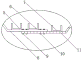
Fig. 1 is a front view of a telescopic device for a corrugated steel structure according to the present invention;
fig. 2 is an enlarged view of a connecting mechanism of a telescopic device for a corrugated steel structure according to the present invention;
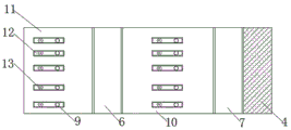
fig. 3 is a top view of the telescopic device for corrugated steel structure according to the present invention.
In the figure: 1 a corrugated steel body; 2. a high strength bolt; 3. a first telescoping device; 4. a second telescoping device; 5. a first channel steel; 6. a second channel steel; 7. a third channel steel; 8. a first planar steel plate ring; 9. a first bolt; 10. a second bolt; 11. a second planar steel plate ring; 12. an expansion joint; 13. a gasket.
Detailed Description
The technical solutions in the embodiments of the present invention will be described clearly and completely with reference to the accompanying drawings in the embodiments of the present invention, and it is obvious that the described embodiments are only some embodiments of the present invention, not all embodiments. Based on the embodiments in the present invention, all other embodiments obtained by a person skilled in the art without creative work belong to the protection scope of the present invention.
In the description of the present invention, it should be noted that the terms "center", "upper", "lower", "left", "right", "vertical", "horizontal", "inner", "outer", and the like indicate orientations or positional relationships based on the orientations or positional relationships shown in the drawings, and are only for convenience of description and simplification of description, but do not indicate or imply that the device or element referred to must have a specific orientation, be constructed and operated in a specific orientation, and thus, should not be construed as limiting the present invention; the terms "first," "second," and "third" are used for descriptive purposes only and are not to be construed as indicating or implying relative importance; furthermore, unless expressly stated or limited otherwise, the terms "mounted," "connected," and "connected" are to be construed broadly, as they may be fixedly connected, detachably connected, or integrally connected, for example; can be mechanically or electrically connected; they may be connected directly or indirectly through intervening media, or they may be interconnected between two elements. The specific meaning of the above terms in the present invention can be understood in specific cases to those skilled in the art.
Referring to fig. 1-3, a telescopic device for a corrugated steel structure comprises a corrugated steel body 1, a first telescopic device 3 is lapped at a groove of the corrugated plate 1, the first telescopic device 3 and a second telescopic device 4 enable rigid connection to be converted into elastic connection, a high-strength bolt 2 is arranged at the lapping position of the corrugated plate 1 and the first telescopic device 3, a high-strength bolt 2 is used for fixing a component, a second telescopic device 4 is lapped at the tail end of the first telescopic device 3, a first flat steel plate ring 8 is welded at one end of the first telescopic device 3, the first flat steel plate ring 8 and a second flat steel plate ring 11 are connecting components, a second flat steel plate ring 11 is welded at one end of the second telescopic device 4 close to the first telescopic device 3, a first channel steel 5 and a second channel steel 6 are welded on the first flat steel plate ring 8, a third channel steel 7 is welded on the second flat steel plate ring 11, be equipped with first bolt 9 between first channel-section steel 5 and the second channel-section steel 6, first bolt 9 and second bolt 10 are fixed first telescoping device 3 and second telescoping device 4, be equipped with second bolt 10 between second channel-section steel 6 and the third channel-section steel 7, and first bolt 9 and second bolt 10 all run through first plane steel sheet plate circle 8 and second plane steel sheet plate circle 11, expansion joint 12 has all been seted up on first plane steel sheet plate circle 8 and the second plane steel sheet plate circle 11, expansion joint 12 elastic connection's main opening, allow rocking at its within range, cup joint on first bolt 9 and the second bolt 10 by packing ring 13.
The first expansion device 3 and the second expansion device 4 have the same structure, one end of the first expansion device is a corrugated plate with the same structure as the corrugated steel main body 1 and is used for being connected with the corrugated steel main body structure, and the other end of the first expansion device is formed by rolling a flat plate with the same outer diameter as the corrugated steel main body structure and is used for connecting the first expansion device 3 and the second expansion device 4;
the longitudinal length of the expansion joint 12 is about 100mm, and two rows are arranged, so that the expansion joint can be firmer;
the diameter of the second plane steel plate ring 11 of the second expansion device 4 is 2-3 plate thicknesses smaller than that of the first plane steel plate ring 8 of the first expansion device 3, so that the two expansion joints 12 can be conveniently spliced or spliced;
the expansion joint 12 is sealed by an engineering rubber gasket and a rectangular flat steel gasket which can cover the expansion joint 12, two groups of first bolts 9 and two groups of second bolts 10 are arranged, and the engineering rubber gasket and the rectangular flat steel gasket achieve the sealing and waterproof effects;
the outer rings of the first expansion device 3 and the second expansion device 4 are welded with channel steel reinforcing ribs in the middle of the two rows of expansion joints 12, and the reinforcing ribs increase the tensile strength.
The working principle is as follows: the utility model relates to a telescopic device for a corrugated steel structure, a first telescopic device 3 is lapped on a corrugated steel main body 1 and is fixed by a high-strength bolt 2, a second flat steel plate ring 11 on a second telescopic device 4 is placed at the bottom end of a first flat steel plate ring 8, a first bolt 9 and a second bolt 10 are used for screwing and fixing in an expansion joint 12 arranged on the first flat steel plate ring 8 and the second flat steel plate ring 11, the second telescopic device 4 is connected with another corrugated steel main body 1 according to the connection method of the first telescopic device 3 and the corrugated steel main body 1, wherein, the first telescopic device 3 and the second telescopic device 4 not only play a role of connecting each corrugated steel main body 1, but also can prevent the structural deformation and even breakage of the corrugated steel main body 1 structure possibly caused under long-term service state, the expansion joint 12 is elastically connected, the corrugated steel body 1 is allowed to rock within the range, and is practical.
Finally, it should be noted that: although the present invention has been described in detail with reference to the foregoing embodiments, it will be apparent to those skilled in the art that modifications and variations can be made in the embodiments or in part of the technical features of the embodiments without departing from the spirit and the scope of the invention.
Claims (6)
1. The utility model provides a telescoping device that corrugated steel structure used, includes corrugated steel main part (1), its characterized in that: the corrugated steel plate is characterized in that a first telescopic device (3) is lapped at a groove of the corrugated steel main body (1), a high-strength bolt (2) is arranged at the lap joint of the corrugated steel main body (1) and the first telescopic device (3), a second telescopic device (4) is lapped at the tail end of the first telescopic device (3), a first flat steel plate ring (8) is welded at one end of the first telescopic device (3), a second flat steel plate ring (11) is welded at one end, close to the first telescopic device (3), of the second telescopic device (4), a first channel steel (5) and a second channel steel (6) are welded on the first flat steel plate ring (8), a third channel steel (7) is welded on the second flat steel plate ring (11), a first bolt (9) is arranged between the first channel steel (5) and the second channel steel (7), and a second bolt (10) is arranged between the second channel steel (6) and the third channel steel (7), and first bolt (9) and second bolt (10) all run through first plane steel sheet plate circle (8) and second plane steel sheet plate circle (11), expansion joint (12) have all been seted up on first plane steel sheet plate circle (8) and second plane steel sheet plate circle (11), cup joint packing ring (13) on first bolt (9) and second bolt (10).
2. The telescopic device for a corrugated steel structure according to claim 1, wherein: first telescoping device (3) and second telescoping device (4) structure is the same, and one end adopts the buckled plate completely the same with corrugated steel main part (1) structure for link to each other with corrugated steel main part structure, the other end adopts and rolls up the system with the dull and stereotyped that corrugated steel main part structure external diameter is the same and form, is used for the connection of first telescoping device (3) and second telescoping device (4).
3. The telescopic device for a corrugated steel structure according to claim 1, wherein: the longitudinal length of the expansion joints (12) is about 100mm, and the expansion joints are arranged in two rows.
4. The telescopic device for a corrugated steel structure according to claim 1, wherein: the diameter of a second plane steel plate ring (11) of the second telescopic device (4) is 2-3 plate thicknesses smaller than that of a first plane steel plate ring (8) of the first telescopic device (3).
5. A telescopic device for a corrugated steel structure, according to claim 3, characterized in that: the expansion joint (12) is sealed by adopting an engineering rubber gasket and a rectangular flat steel gasket capable of covering the expansion joint (12), and the first bolt (9) and the second bolt (10) are provided with two groups.
6. The telescopic device for a corrugated steel structure according to claim 1, wherein: and channel steel reinforcing ribs are welded between the two rows of expansion joints (12) on the outer rings of the first expansion device (3) and the second expansion device (4).
Priority Applications (1)
| Application Number | Priority Date | Filing Date | Title |
|---|---|---|---|
| CN201921309397.7U CN210597065U (en) | 2019-08-14 | 2019-08-14 | Expansion device for corrugated steel structure |
Applications Claiming Priority (1)
| Application Number | Priority Date | Filing Date | Title |
|---|---|---|---|
| CN201921309397.7U CN210597065U (en) | 2019-08-14 | 2019-08-14 | Expansion device for corrugated steel structure |
Publications (1)
| Publication Number | Publication Date |
|---|---|
| CN210597065U true CN210597065U (en) | 2020-05-22 |
Family
ID=70713967
Family Applications (1)
| Application Number | Title | Priority Date | Filing Date |
|---|---|---|---|
| CN201921309397.7U Ceased CN210597065U (en) | 2019-08-14 | 2019-08-14 | Expansion device for corrugated steel structure |
Country Status (1)
| Country | Link |
|---|---|
| CN (1) | CN210597065U (en) |
-
2019
- 2019-08-14 CN CN201921309397.7U patent/CN210597065U/en not_active Ceased
Similar Documents
| Publication | Publication Date | Title |
|---|---|---|
| CN210597065U (en) | Expansion device for corrugated steel structure | |
| CN103526776B (en) | Towards immersed tube tunnel rubber fastening band hardness layered approach and rubber fastening band thereof | |
| CN112324456A (en) | Shield tunnel composite lining structure and method | |
| CN110873247A (en) | Hydraulic engineering is with pipeline of convenient concatenation | |
| CN206581133U (en) | The special interior extended surface waterstop of Expansion Units for Highway Bridges | |
| CN206189610U (en) | Sliding connection between steel member and concrete | |
| CN214614184U (en) | Steel-edged rubber water stop and pipe gallery splicing structure with improved splicing part | |
| CN210531792U (en) | Double-layer metal framework reinforced composite plastic pipeline | |
| CN212455819U (en) | Anti-freezing heat-preservation type polymer hose | |
| CN211259911U (en) | Petroleum pipeline sealing device | |
| CN107060817B (en) | Shield machinable prefabricated pipe section structure | |
| CN210947346U (en) | Floor cracking prevention and control structure | |
| CN208169729U (en) | A kind of low pressure Prestressed concrete cylinder pipe and defeated drainage pipeline | |
| CN208830820U (en) | A kind of inserted overturn-preventing limiting device of mast lifting construction | |
| CN201835294U (en) | Rubber water-stop for underground building settlement joint | |
| CN217500337U (en) | High-elastic tensile multi-purpose steel edge type rubber waterstop | |
| CN220770386U (en) | Steel band reinforced spiral corrugated pipe | |
| CN215166670U (en) | Composite water-stopping steel belt with water-swelling water-stopping strip | |
| CN211735507U (en) | Take waterproof device in prefabricated piping lane piece of clamp plate | |
| CN218563666U (en) | Large-diameter shield segment structure | |
| CN211525710U (en) | Anti-overflow wall-penetrating embedded pipe fitting | |
| CN216664749U (en) | High sealing connection's steel construction building ceiling of avoiding seepage | |
| CN210621509U (en) | Corrugated steel pipe for emergency rescue of highway | |
| CN209905346U (en) | Height compensator for transporting bridge prefabricated sections | |
| CN208545623U (en) | Horizontal connection assembly type shear hinge |
Legal Events
| Date | Code | Title | Description |
|---|---|---|---|
| GR01 | Patent grant | ||
| GR01 | Patent grant | ||
| IW01 | Full invalidation of patent right |
Decision date of declaring invalidation: 20220119 Decision number of declaring invalidation: 53587 Granted publication date: 20200522 |
|
| IW01 | Full invalidation of patent right |