CN210590193U - Cooling device is used in polyurethane foam processing - Google Patents
Cooling device is used in polyurethane foam processing Download PDFInfo
- Publication number
- CN210590193U CN210590193U CN201921170663.2U CN201921170663U CN210590193U CN 210590193 U CN210590193 U CN 210590193U CN 201921170663 U CN201921170663 U CN 201921170663U CN 210590193 U CN210590193 U CN 210590193U
- Authority
- CN
- China
- Prior art keywords
- plate
- welded
- polyurethane foam
- top wall
- damping
- Prior art date
- Legal status (The legal status is an assumption and is not a legal conclusion. Google has not performed a legal analysis and makes no representation as to the accuracy of the status listed.)
- Active
Links
Images


Landscapes
- Processing And Handling Of Plastics And Other Materials For Molding In General (AREA)
Abstract
The utility model belongs to the field of polyurethane foam plastic processing equipment, in particular to a cooling device for polyurethane foam plastic processing, aiming at the problems of larger vibration generated by the operation of the existing cooling device for polyurethane foam plastic processing, larger working noise, poorer cooling effect and poorer working quality of the existing cooling device for polyurethane foam plastic processing, the following proposal is proposed, which comprises a base and a supporting plate, wherein the supporting plate is arranged right above the base, two springs which are symmetrically arranged are connected between the base and the supporting plate, a horizontally arranged rubber plate is fixed on the bottom wall of the base through screws, a damping box without a bottom wall is welded on the top wall of the base, the horizontally arranged damping plate is movably sleeved on the inner side wall of the damping box, a plurality of movable holes are equidistantly arranged on the top wall of the damping box, the utility model generates smaller vibration during the operation, the working noise is less, and the cooling effect is good, and operating mass is higher.
Description
Technical Field
The utility model relates to a polyurethane foam processing equipment technical field especially relates to a cooling device is used in polyurethane foam processing.
Background
The processing steps of the polyurethane foam plastic generally comprise the steps of dosing, forming, machining, jointing, modifying and the like of the plastic, and the polyurethane foam plastic generally has high temperature after being formed and needs to be cooled in time to ensure the smoothness of a product. However, the existing cooling device for processing polyurethane foam plastic has larger vibration generated during working, so that the working noise is larger, and the existing cooling device for processing polyurethane foam plastic has poorer cooling effect and poorer working quality.
SUMMERY OF THE UTILITY MODEL
The utility model provides a pair of cooling device is used in polyurethane foam processing, it is great to have solved the vibrations of the production of current cooling device work for polyurethane foam processing, leads to noise at work great, and current cooling device is used in polyurethane foam processing's cooling effect is relatively poor, the relatively poor problem of operating mass with rated load.
In order to achieve the above purpose, the utility model adopts the following technical scheme:
a cooling device for processing polyurethane foam plastic comprises a base and a supporting plate, wherein the supporting plate is arranged right above the base, two springs which are symmetrically arranged are connected between the base and the supporting plate, a horizontally arranged rubber plate is fixed on the bottom wall of the base through screws, a damping box without a bottom wall is welded on the top wall of the base, a horizontally arranged damping plate is movably sleeved on the inner side wall of the damping box, a plurality of movable holes are formed in the top wall of the damping box at equal intervals, a vertically arranged damping column is movably sleeved in the movable holes, the bottom end of the damping column extends into the damping box and is welded on the top wall of the damping plate, the top end of the damping column is positioned above the damping box and is welded on the bottom wall of the supporting plate, a vertically arranged rotating column is rotatably connected at the middle position of the top wall of the supporting plate, and a conical gear ring is fixedly sleeved on the outer ring of the rotating column positioned above the supporting plate, a horizontally arranged driving motor is installed on the top wall of the supporting plate, bevel gears are welded at the output ends of the driving motor, a bevel gear ring is meshed with the bevel gears, a horizontally arranged second rotating plate is welded at the top ends of the rotating columns, a plurality of vertically arranged second fixing columns distributed in a rectangular array are welded on the top wall of the second rotating plate, two vertically arranged gas collecting pipes are symmetrically welded on the top wall of the supporting plate and are respectively positioned at two sides of the second rotating plate, gas outlet holes are formed in the pipe walls, close to each other, of the two gas collecting pipes at equal intervals from top to bottom, two air pumps are installed on the top wall of the supporting plate, the gas outlet pipes of the air pumps extend to the insides of the gas collecting pipes, horizontally arranged top plates are welded at the top ends of the two gas collecting pipes, and two hydraulic push rods with downward output ends are symmetrically installed on the bottom wall of the, the hydraulic push rod device comprises two hydraulic push rods, and is characterized in that the output ends of the two hydraulic push rods are welded with lifting plates horizontally arranged, first rotating plates horizontally arranged are rotatably connected under the lifting plates, and a plurality of vertically arranged first fixing columns distributed in a rectangular array are welded on the bottom wall of each first rotating plate.
Preferably, the mounting groove has been seted up on the roof of backup pad, and the fixed first bearing cover that has cup jointed in the mounting groove, the fixed inner circle that cup joints at first bearing cover in bottom of rotation post, the mounting hole has been seted up to the intermediate position of lifter plate, and the fixed second bearing cover that has cup jointed in the mounting hole, and the fixed cover of inner circle of second bearing cover has connect the pivot, the bottom welding of pivot is on the roof of first rotation board.
Preferably, the two springs are respectively located on two sides of the shock absorption box, the two gas collecting pipes are located between the two air pumps, and the first rotating plate is located right above the second rotating plate.
Preferably, the size of the shock absorbing plate is matched with the size of the inner side wall of the shock absorbing box.
Preferably, a plurality of anti-skidding grooves are formed in the bottom wall of the rubber plate at equal intervals.
In the utility model
1. Through the cooperation of rubber damper, shock attenuation board, shock attenuation post, spring and rubber slab, can promote polyurethane foam processing and use cooling device's damping performance, the effectual vibrations that produce during operation of reducing polyurethane foam processing and using cooling device to effectual reduction noise at work.
2. Through air pump, discharge, venthole, roof, hydraulic push rod, lifter plate, pivot, first rotation board, first fixed column, rotation post, ring gear, driving motor, gear, second rotation board and the mating reaction of second fixed column, can make polyurethane foam receive even blowing, promote the cooling effect, work quality is higher.
Drawings
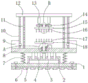
Fig. 1 is a schematic structural diagram of a cooling device for processing polyurethane foam provided by the present invention.
FIG. 2 is a partial enlarged view of a portion A of a cooling apparatus for polyurethane foam processing according to the present invention.
FIG. 3 is a partial enlarged view of a portion B of a cooling apparatus for polyurethane foam processing according to the present invention.
Fig. 4 is a bottom view of the first rotating plate of the cooling device for polyurethane foam processing according to the present invention.
Fig. 5 is a top view of a second rotating plate of a cooling device for polyurethane foam processing according to the present invention.
Reference numbers in the figures: the vibration damping device comprises a base 1, a vibration damping box 2, a vibration damping plate 3, a vibration damping column 4, a rubber plate 5, an anti-skidding groove 6, a spring 7, a supporting plate 8, an air pump 9, a gas collecting pipe 10, an air outlet hole 11, a top plate 12, a hydraulic push rod 13, a lifting plate 14, a first rotating plate 15, a first fixing column 16, a second fixing column 17, a second rotating plate 18, a rotating column 19, a bevel gear ring 20, a driving motor 21, a bevel gear ring 22 and a rotating shaft 23.
Detailed Description
The technical solutions in the embodiments of the present invention will be described clearly and completely with reference to the accompanying drawings in the embodiments of the present invention, and it is obvious that the described embodiments are only some embodiments of the present invention, not all embodiments.
Referring to fig. 1-5, a cooling device for polyurethane foam processing comprises a base 1 and a supporting plate 8, wherein the supporting plate 8 is installed right above the base 1, two springs 7 which are symmetrically arranged are connected between the base 1 and the supporting plate 8, a horizontally arranged rubber plate 5 is fixed on the bottom wall of the base 1 through screws, a damping box 2 without a bottom wall is welded on the top wall of the base 1, a horizontally arranged damping plate 3 is movably sleeved on the inner side wall of the damping box 2, a plurality of movable holes are equidistantly formed on the top wall of the damping box 2, a vertically arranged damping column 4 is movably sleeved in each movable hole, the bottom end of each damping column 4 extends into the damping box 2 and is welded on the top wall of the damping plate 3, the top end of each damping column 4 is positioned above the damping box 2 and is welded on the bottom wall of the supporting plate 8, a vertically arranged rotating column 19 is rotatably connected at the middle position of the top wall of the supporting plate, a bevel gear ring 20 is fixedly sleeved on the outer ring of the rotating column 19 positioned above the supporting plate 8, a horizontally arranged driving motor 21 is installed on the top wall of the supporting plate 8, a bevel gear 22 is welded at the output end of the driving motor 21, the bevel gear ring 20 is meshed with the bevel gear 22, a horizontally arranged second rotating plate 18 is welded at the top end of the rotating column 19, a plurality of vertically arranged second fixing columns 17 distributed in a rectangular array are welded on the top wall of the second rotating plate 18, two vertically arranged gas collecting pipes 10 are symmetrically welded on the top wall of the supporting plate 8, the two gas collecting pipes 10 are respectively positioned at two sides of the second rotating plate 18, gas outlet holes 11 are respectively formed in the pipe walls, close to each other, of the two gas collecting pipes 10 at equal intervals from top to bottom, two gas pumps 9 are installed on the top wall of the supporting plate 8, the gas outlet pipes of the gas pumps 9 extend to the insides of the gas collecting pipes, two hydraulic push rods 13 with downward output ends are symmetrically installed on the bottom wall of the top plate 12, the output ends of the two hydraulic push rods 13 are welded with a lifting plate 14 which is horizontally arranged, a first rotating plate 15 which is horizontally arranged is rotatably connected under the lifting plate 14, and a plurality of vertically arranged first fixing columns 16 which are distributed in a rectangular array are welded on the bottom wall of the first rotating plate 15.
The mounting groove has been seted up on backup pad 8's the roof, the fixed cover of fixed cover in the mounting groove has been connected first bearing cover, the fixed inner circle of cup jointing at first bearing cover in the bottom of rotating column 19, the mounting hole has been seted up to lifter plate 14's intermediate position, the fixed cover of cup jointing has second bearing cover in the mounting hole, the fixed cover of inner circle of second bearing cover has been connected pivot 23, the bottom welding of pivot 23 is on the roof of first rotor plate 15, two springs 7 are located the both sides of surge tank 2 respectively, two discharge pipes 10 are located between two air pumps 9, first rotor plate 15 is located second rotor plate 18 directly over, the size of surge tank 3 and the size looks adaptation of 2 inside walls of surge tank, a plurality of antiskid groove 6 have been seted up to the equidistance.
In the description of the present invention, it is to be understood that the terms "center", "longitudinal", "lateral", "length", "width", "thickness", "upper", "lower", "front", "rear", "left", "right", "vertical", "horizontal", "top", "bottom", "inner", "outer", "clockwise", "counterclockwise", and the like indicate orientations or positional relationships based on the orientations or positional relationships shown in the drawings, and are only for convenience of description and to simplify the description, but do not indicate or imply that the device or element referred to must have a particular orientation, be constructed and operated in a particular orientation, and therefore should not be construed as limiting the present invention.
Furthermore, the terms "first", "second" and "first" are used for descriptive purposes only and are not to be construed as indicating or implying relative importance or implicitly indicating the number of technical features indicated. Thus, a feature defined as "first" or "second" may explicitly or implicitly include one or more of that feature. In the description of the present invention, "a plurality" means two or more unless specifically limited otherwise.
The working principle is as follows: placing the formed polyurethane foam plastic on the top of the second fixing columns 17, pushing the lifting plate 14 to descend by the extension of the hydraulic push rod 13, so that the lifting plate 14 can push the first rotating plate 15 and the first fixing columns 16 to descend until the bottom ends of the first fixing columns 16 are abutted against the top surfaces of the polyurethane foam plastic, so that the polyurethane foam plastic can be effectively fixed, then blowing the polyurethane foam plastic through the air outlets 11 uniformly distributed on the air collecting pipe 10 by the operation of the air pump 9, driving the rotating columns 19 to rotate by the operation of the bevel gears 22 and the bevel gear rings 20 by the operation of the driving motor 21, so that the second rotating plate 18 and the second fixing columns 17 can be driven to rotate, so that the polyurethane foam plastic is uniformly blown, the cooling effect is improved, and the supporting plate 8 can be driven to generate large vibration when the air pump 9 and the driving motor 21 operate, make spring 7 constantly flexible, through the elastic potential energy effect of spring 7, can make spring 7 return rapidly, can make backup pad 8 return rapidly, reduce backup pad 8's vibrations to reduce the vibrations that whole device during operation produced, through the setting of rubber slab 5, can further promote the shock attenuation effect, through the setting of antiskid groove 6, can promote the frictional force on whole device and ground, prevent that whole device during operation from taking place the skew, the utility model discloses the vibrations that the during operation produced are less, and noise at work is less, and the cooling effect is good, and operating mass is higher.
The above, only be the concrete implementation of the preferred embodiment of the present invention, but the protection scope of the present invention is not limited thereto, and any person skilled in the art is in the technical scope of the present invention, according to the technical solution of the present invention and the utility model, the concept of which is equivalent to replace or change, should be covered within the protection scope of the present invention.
Claims (5)
1. A cooling device for polyurethane foam plastic processing comprises a base (1) and a support plate (8), and is characterized in that the support plate (8) is installed right above the base (1), two springs (7) which are symmetrically arranged are connected between the base (1) and the support plate (8), a rubber plate (5) which is horizontally arranged is fixed on the bottom wall of the base (1) through screws, a damping box (2) without a bottom wall is welded on the top wall of the base (1), a damping plate (3) which is horizontally arranged is movably sleeved on the inner side wall of the damping box (2), a plurality of movable holes are equidistantly formed in the top wall of the damping box (2), damping columns (4) which are vertically arranged are movably sleeved in the movable holes, the bottom ends of the damping columns (4) extend to the inside of the damping box (2) and are welded on the top wall of the damping plate (3), the top end of the shock absorption column (4) is positioned above the shock absorption box (2) and welded on the bottom wall of the support plate (8), the middle position of the top wall of the support plate (8) is rotationally connected with a vertically arranged rotating column (19), an outer ring of the rotating column (19) positioned above the support plate (8) is fixedly sleeved with a bevel gear ring (20), a horizontally arranged driving motor (21) is installed on the top wall of the support plate (8), a bevel gear (22) is welded at the output end of the driving motor (21), the bevel gear ring (20) is meshed and connected with the bevel gear (22), a horizontally arranged second rotating plate (18) is welded at the top end of the rotating column (19), a plurality of vertically arranged second fixing columns (17) distributed in a rectangular array are welded on the top wall of the second rotating plate (18), two vertically arranged gas collection pipes (10) are symmetrically welded on the top wall of the support plate (8), the two gas collecting pipes (10) are respectively positioned at two sides of the second rotating plate (18), the pipe walls of the two gas collecting pipes (10) which are close to each other are provided with gas outlet holes (11) at equal intervals from top to bottom, two air pumps (9) are arranged on the top wall of the supporting plate (8), an air outlet pipe of each air pump (9) extends to the inside of each air collecting pipe (10), a top plate (12) which is horizontally arranged is welded at the top ends of the two air collecting pipes (10), two hydraulic push rods (13) with downward output ends are symmetrically arranged on the bottom wall of the top plate (12), the output ends of the two hydraulic push rods (13) are welded with a lifting plate (14) which is horizontally arranged, a first rotating plate (15) which is horizontally arranged is rotatably connected under the lifting plate (14), the bottom wall of the first rotating plate (15) is welded with a plurality of vertically arranged first fixing columns (16) distributed in a rectangular array.
2. The cooling device for polyurethane foam processing as recited in claim 1, wherein a mounting groove is formed in the top wall of the support plate (8), a first bearing sleeve is fixedly sleeved in the mounting groove, the bottom of the rotating column (19) is fixedly sleeved on the inner ring of the first bearing sleeve, a mounting hole is formed in the middle position of the lifting plate (14), a second bearing sleeve is fixedly sleeved in the mounting hole, a rotating shaft (23) is fixedly sleeved on the inner ring of the second bearing sleeve, and the bottom end of the rotating shaft (23) is welded on the top wall of the first rotating plate (15).
3. The cooling device for polyurethane foam processing according to claim 1, wherein the two springs (7) are respectively located at both sides of the damper box (2), the two gas collecting pipes (10) are located between the two gas pumps (9), and the first rotating plate (15) is located directly above the second rotating plate (18).
4. A cooling device for polyurethane foam processing according to claim 1, wherein the size of said damper plate (3) is adapted to the size of the inner side wall of said damper box (2).
5. The cooling device for polyurethane foam processing as recited in claim 1, wherein a plurality of anti-slip grooves (6) are formed on the bottom wall of the rubber plate (5) at equal intervals.
Priority Applications (1)
| Application Number | Priority Date | Filing Date | Title |
|---|---|---|---|
| CN201921170663.2U CN210590193U (en) | 2019-07-24 | 2019-07-24 | Cooling device is used in polyurethane foam processing |
Applications Claiming Priority (1)
| Application Number | Priority Date | Filing Date | Title |
|---|---|---|---|
| CN201921170663.2U CN210590193U (en) | 2019-07-24 | 2019-07-24 | Cooling device is used in polyurethane foam processing |
Publications (1)
| Publication Number | Publication Date |
|---|---|
| CN210590193U true CN210590193U (en) | 2020-05-22 |
Family
ID=70719665
Family Applications (1)
| Application Number | Title | Priority Date | Filing Date |
|---|---|---|---|
| CN201921170663.2U Active CN210590193U (en) | 2019-07-24 | 2019-07-24 | Cooling device is used in polyurethane foam processing |
Country Status (1)
| Country | Link |
|---|---|
| CN (1) | CN210590193U (en) |
-
2019
- 2019-07-24 CN CN201921170663.2U patent/CN210590193U/en active Active
Similar Documents
| Publication | Publication Date | Title |
|---|---|---|
| CN209175323U (en) | A kind of big Workpiece clamping tooling of wind-power electricity generation with lock function | |
| CN210876686U (en) | Processing dust cleaning device of loader transaxle | |
| CN211424565U (en) | Air purifier convenient to remove | |
| CN210590193U (en) | Cooling device is used in polyurethane foam processing | |
| CN210605572U (en) | High-efficient radiating computer mainframe | |
| CN110932139A (en) | Power equipment box supports base | |
| CN213176446U (en) | Crankshaft device of press machine equipment | |
| CN109249333B (en) | Turnover saw blade and flange assembling device and assembling method | |
| CN215280217U (en) | Improved portable high-power electric spark machine | |
| CN112728056B (en) | Worm gear speed reducer | |
| CN214130883U (en) | A dust collector for construction | |
| CN210207116U (en) | Renewable resource comprehensive recovery device system | |
| CN211116533U (en) | Novel horizontal pump unit for diesel power well | |
| CN210461144U (en) | Fixing mechanism of fan | |
| CN215942705U (en) | Workpiece overturning tool for automobile manufacturing | |
| CN217191896U (en) | High-efficient stamping device of cell-phone signal receiver shell | |
| CN218151481U (en) | Submersible electric pump | |
| CN215146707U (en) | Protective device of numerical control machine tool | |
| CN215701896U (en) | Rotary type tire trimming device | |
| CN210613118U (en) | Environment-friendly dust removal device | |
| CN214980594U (en) | Intelligent positioning and supporting device for installation | |
| CN110905790A (en) | Novel horizontal pump unit for diesel power well | |
| CN210756709U (en) | Lathe with shock-absorbing function | |
| CN108817213A (en) | A kind of handware punching machine for processing easy to repair | |
| CN211868553U (en) | Full automated inspection extrusion lines of nylon tube |
Legal Events
| Date | Code | Title | Description |
|---|---|---|---|
| GR01 | Patent grant | ||
| GR01 | Patent grant |