CN210589593U - Special-shaped cutting machine is used in sponge production - Google Patents
Special-shaped cutting machine is used in sponge production Download PDFInfo
- Publication number
- CN210589593U CN210589593U CN201920869150.4U CN201920869150U CN210589593U CN 210589593 U CN210589593 U CN 210589593U CN 201920869150 U CN201920869150 U CN 201920869150U CN 210589593 U CN210589593 U CN 210589593U
- Authority
- CN
- China
- Prior art keywords
- cutting machine
- sponge
- sponge production
- sliding
- belt
- Prior art date
- Legal status (The legal status is an assumption and is not a legal conclusion. Google has not performed a legal analysis and makes no representation as to the accuracy of the status listed.)
- Expired - Fee Related
Links
Images


Abstract
The utility model provides a special-shaped cutting machine is used in sponge production. The special-shaped cutting machine for sponge production comprises a conveyor; the cutting machine body is fixedly arranged on the conveyor; the two upright columns are fixedly arranged at the top of the conveyor; the transverse plate is fixedly arranged at the tops of the two upright posts; the two sliding grooves are respectively arranged on the corresponding upright posts, and the tops of the two sliding grooves are both of an open structure; and the two sliding blocks are respectively arranged in the corresponding sliding grooves in a sliding manner. The utility model provides a pair of dysmorphism cutting machine is used in sponge production has convenient to use, economical and practical, can utilize the roller to fix a position the sponge according to the height adjustment of the sponge of different thickness to the sponge can be tiled on the conveyer belt, improve the advantage of cutting efficiency and cutting quality.
Description
Technical Field
The utility model relates to a cutting machine field especially relates to a special-shaped cutting machine is used in sponge production.
Background
The sponge cutting machine is a machine for cutting the sponge piecemeal, the type of sponge cutting machine is more, multiple model has, can divide into truncation machine, the angle cutting machine, the machine of pressing, dysmorphism machine, straight cutting machine etc., wherein dysmorphism sponge cutting machine's use is more and more extensive, dysmorphism sponge cutting machine and can cut the sponge into required shape as required, the cooperation conveyer uses, among the prior art, the model is that a sponge production of HK-SZD2023 passes through computer program control with special-shaped cutting machine, degree of automation is high, whole cutting effect has, sponge cutting integrated into one piece, and can cut the sponge into required arbitrary shape according to the demand.
However, when the sponge is cut by the traditional special-shaped cutting machine, the sponge is generally directly placed on a conveyor to be cut, usually, the sponge cannot be positioned when the sponge is cut, the sponge is easy to shift in the cutting process, and the sponge is easy to tilt or generate folds due to the fact that the sponge is soft, so that the cutting quality can be reduced, and the working efficiency is reduced.
Therefore, it is necessary to provide a new profile cutting machine for sponge production to solve the above technical problems.
SUMMERY OF THE UTILITY MODEL
The utility model provides a technical problem provide a convenient to use, economical and practical can utilize the roller to fix a position the sponge according to the height adjustment of the sponge of different thickness to the sponge to can tile the sponge on the conveyer belt, improve the special-shaped cutting machine is used in sponge production of cutting efficiency and cutting quality.
In order to solve the technical problem, the utility model provides a pair of special-shaped cutting machine is used in sponge production includes: a conveyor; the cutting machine body is fixedly arranged on the conveyor; the two upright columns are fixedly arranged at the top of the conveyor; the transverse plate is fixedly arranged at the tops of the two upright posts; the two sliding grooves are respectively arranged on the corresponding upright posts, and the tops of the two sliding grooves are both of an open structure; the two sliding blocks are respectively installed in the corresponding sliding grooves in a sliding mode, and one side of each sliding block extends out of the corresponding sliding groove; the roll shaft is positioned between the two sliding blocks; elevating system, elevating system fixed mounting is two on the stand, elevating system includes two screw holes, two lead screws, two mounting holes, two connecting axles, two first belt pulleys, pivot, two second belt pulleys and two belts, set up respectively at the top of corresponding slider for two screw holes, two the screw hole is located correspondingly respectively in the spout.
Preferably, two the lead screw is respectively the threaded mounting corresponding in the threaded hole, the both ends of lead screw all extend to outside the screw hole, two the mounting hole is all seted up the top of diaphragm, two the mounting hole respectively with corresponding spout intercommunication, two the connecting axle rotates respectively to be installed corresponding in the mounting hole, the both ends of connecting axle extend respectively to outside the mounting hole, two the bottom of connecting axle respectively with corresponding the top fixed connection of lead screw, two first belt pulley fixed cover respectively is established correspondingly the top of connecting axle, the pivot is located the top of diaphragm, two the equal fixed cover of second belt pulley is established in the pivot, two the belt is respectively around establishing at corresponding on first belt pulley and the second belt pulley.
Preferably, the inner walls of the bottoms of the two sliding grooves are fixedly provided with first bearing seats, and the bottom ends of the two screw rods are rotatably arranged on the corresponding first bearing seats respectively.
Preferably, balls are nested on one sides, far away from each other, of the two sliding blocks, and the two balls are in rolling contact with the inner wall of one side of the corresponding sliding groove respectively.
Preferably, the two sliding blocks are fixedly provided with a second bearing seat at one side close to each other, and two ends of the roll shaft are respectively rotatably arranged on the corresponding second bearing seats.
Preferably, bearings are fixedly sleeved on the two connecting shafts, and outer rings of the two bearings are fixedly connected with the corresponding inner walls of the mounting holes respectively.
Preferably, the top fixed mounting of diaphragm has the shell, two first belt pulley and two the second belt pulley all is located in the shell, the top of pivot runs through shell and fixed mounting has the handle, the anti-skidding line has been seted up on the handle.
Compared with the prior art, the utility model provides a pair of dysmorphism cutting machine is used in sponge production has following beneficial effect:
the utility model provides a special-shaped cutting machine for sponge production, the sponge to be cut is placed on the conveyer belt, the handle is clockwise rotated, the handle drives the rotating shaft and two second belt wheels to rotate, two second belt wheels drive the corresponding first belt wheels to rotate through the corresponding belts, two first belt wheels drive the corresponding connecting shaft and the corresponding lead screws to rotate, two sliding blocks slide downwards in the corresponding chutes, two sliding blocks drive the roller shaft to move downwards, when the roller shaft moves downwards to contact with the upper surface of the sponge to be processed, the handle stops rotating, then the cutting machine body can be started to work, the sponge is cut by the cutting machine body, the sponge can be fixed on the conveyer belt by the roller shaft, avoid the sponge to take place the skew when the cutting, finish the back to one section sponge cutting, start conveyer work, conveyer belt on the conveyer conveys the sponge, and the sponge promotes in the data send process the roller rotates, simultaneously usable the roller flattens the sponge, paves the sponge on the conveyer belt to improved cutting quality and cutting efficiency, the cutting finishes the back, stops the conveyer with cutting machine body work can, the same reason, anticlockwise rotation the handle, two the slider drives the roller rebound can be according to the thickness of different sponges right the height of roller is adjusted.
Drawings
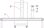
Fig. 1 is a schematic structural diagram of a preferred embodiment of a special-shaped cutting machine for sponge production according to the present invention;
FIG. 2 is an enlarged view of portion A of FIG. 1;
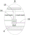
FIG. 3 is an enlarged view of the portion B shown in FIG. 1;
fig. 4 is a schematic side view of the present invention.
Reference numbers in the figures: 1. conveyer, 2, cutting machine body, 3, stand, 4, diaphragm, 5, spout, 6, slider, 7, roller, 8, screw hole, 9, lead screw, 10, mounting hole, 11, connecting axle, 12, first belt pulley, 13, pivot, 14, second belt pulley, 15, belt.
Detailed Description
The present invention will be further described with reference to the accompanying drawings and embodiments.
Please refer to fig. 1, fig. 2, fig. 3 and fig. 4, wherein fig. 1 is a schematic structural diagram of a special-shaped cutting machine for sponge production according to a preferred embodiment of the present invention; FIG. 2 is an enlarged view of portion A of FIG. 1; FIG. 3 is an enlarged view of the portion B shown in FIG. 1; fig. 4 is a schematic side view of the present invention. A sponge production is with dysmorphism cutting machine includes: a conveyor 1; the cutting machine body 2 is fixedly arranged on the conveyor 1; the two upright columns 3 are fixedly arranged at the top of the conveyor 1; the transverse plate 4 is fixedly arranged at the tops of the two upright posts 3; the two sliding grooves 5 are respectively arranged on the corresponding upright posts 3, and the tops of the two sliding grooves 5 are both of an open structure; the two sliding blocks 6 are respectively installed in the corresponding sliding grooves 5 in a sliding mode, and one side of each sliding block 6 extends out of the corresponding sliding groove 5; the roller shaft 7 is positioned between the two sliding blocks 6; elevating system, elevating system fixed mounting is two on the stand 3, elevating system includes two screw holes 8, two lead screws 9, two mounting holes 10, two connecting axles 11, two first belt pulleys 12, pivot 13, two second belt pulleys 14 and two belts 15, set up respectively at the top of corresponding slider 6, two screw holes 8 are located correspondingly respectively in the spout 5.
The two screw rods 9 are respectively installed in the corresponding threaded holes 8 in a threaded manner, two ends of each screw rod 9 extend out of the corresponding threaded hole 8, the two mounting holes 10 are formed in the top of the transverse plate 4, the two mounting holes 10 are respectively communicated with the corresponding sliding grooves 5, the two connecting shafts 11 are respectively installed in the corresponding mounting holes 10 in a rotating manner, two ends of the connecting shaft 11 respectively extend out of the mounting holes 10, the bottom ends of the two connecting shafts 11 are respectively fixedly connected with the top ends of the corresponding screw rods 9, the two first belt pulleys 12 are respectively fixedly sleeved on the top ends of the corresponding connecting shafts 11, the pivot 13 is located the top of diaphragm 4, two the equal fixed cover of second belt pulley 14 is established in the pivot 13 is last, two the belt 15 is respectively around establishing correspondingly on first belt pulley 12 and the second belt pulley 14.
The inner walls of the bottoms of the two sliding grooves 5 are fixedly provided with first bearing seats, and the bottom ends of the two screw rods 9 are respectively and rotatably arranged on the corresponding first bearing seats.
Two the mutual one side of keeping away from of slider 6 all nestedly has the ball, two the ball respectively with corresponding one side inner wall rolling contact of spout 5.
Two slide blocks 6 are all fixed mounting with the second bearing frame in the one side that is close to each other, the both ends of roller 7 rotate respectively to be installed on corresponding the second bearing frame.
Bearings are fixedly sleeved on the two connecting shafts 11, and outer rings of the two bearings are fixedly connected with the corresponding inner walls of the mounting holes 10 respectively.
The top fixed mounting of diaphragm 4 has the shell, two first belt pulley 12 and two second belt pulley 15 all is located in the shell, shell and fixed mounting are run through on the top of pivot 13 have the handle, the anti-skidding line has been seted up on the handle.
The utility model provides a pair of dysmorphism cutting machine is used in sponge production's theory of operation as follows:
the cutting machine is characterized in that the type of the cutting machine body 2 is HK-SZD2023, a conveyor belt is rotatably mounted on the conveyor 1, a control box is arranged on one side of the cutting machine body 2, a control switch and an external power line are fixedly mounted on the control box, the conveyor 1, the cutting machine body 2, the control box and the external power line are electrically connected in sequence to form a closed loop, and the control switch controls the starting and stopping work of the conveyor 1 and the cutting machine body 2;
when the sponge is cut, firstly, the sponge to be cut is placed on a conveyor belt, and the handle is rotated clockwise;
the handle drives the rotating shaft 13 and the two second belt pulleys 14 to rotate;
the two second belt pulleys 14 drive the corresponding first belt pulleys 12 to rotate under the transmission action of the corresponding belts 15;
the two first belt pulleys 12 drive the corresponding connecting shafts 11 and the corresponding screw rods 9 to rotate;
when the two screw rods 9 rotate, the two slide blocks 6 slide downwards in the corresponding slide grooves 5, the two slide blocks 6 drive the corresponding balls to roll, and when the balls roll, the friction resistance of the slide blocks 6 during sliding can be greatly reduced, so that the slide blocks 6 can slide more smoothly;
the two sliding blocks 6 drive the roller shaft 7 to move downwards, and when the roller shaft 7 moves downwards to be in contact with the upper surface of the sponge to be processed, the handle stops rotating;
then, the cutting machine body 2 can be started to work, the sponge is cut by the cutting machine body 2, and the sponge can be fixed on a conveying belt by the roller shaft 7, so that the sponge is prevented from being deviated during cutting;
after a section of sponge is cut, the conveyor 1 is started to work, the conveyor belt on the conveyor 1 conveys the sponge, the roller 7 is pushed to rotate in the conveying process of the sponge, and meanwhile, the sponge can be flattened by the roller 7, so that the sponge is not tilted and is laid on the conveyor belt, and the cutting quality and the cutting efficiency are improved;
after cutting, stopping the conveyor 1 and the cutting machine body 2;
in a similar way, the handle rotates anticlockwise, the two sliding blocks 6 drive the roller shaft 7 to move upwards, and the height of the roller shaft 7 can be adjusted according to the thickness of different sponges.
Compared with the prior art, the utility model provides a pair of dysmorphism cutting machine is used in sponge production has following beneficial effect:
the utility model provides a special-shaped cutting machine for sponge production, the sponge to be cut is placed on the conveyer belt, the handle is rotated clockwise, the handle drives the rotating shaft 13 and two second belt wheels 14 to rotate, two second belt wheels 14 drive the corresponding first belt wheel 12 to rotate through the corresponding belt 15, two first belt wheels 12 drive the corresponding connecting shaft 11 and the corresponding lead screw 9 to rotate, two sliders 6 slide downwards in the corresponding chutes 5, two sliders 6 drive the roller shaft 7 to move downwards, when the roller shaft 7 moves downwards to contact with the upper surface of the sponge to be processed, the handle stops rotating, then the cutting machine body 2 can be started to work, the sponge is cut by the cutting machine body 2, utilize roller 7 can fix the sponge on the conveyer belt, avoids the sponge to take place the skew when the cutting, finishes the back to one section sponge, starts conveyer 1 work, conveyer belt on the 1 conveyer conveys the sponge, and the sponge promotes in data send process roller 7 rotates, and is simultaneously usable roller 7 flattens the sponge, paves the sponge on the conveyer belt to improved cutting quality and cutting efficiency, the cutting finishes the back, stops conveyer 1 with 2 work of cutting machine body can, the same reason, anticlockwise rotation the handle, two slider 6 drives roller 7 rebound can be right according to the thickness of different sponges roller 7 highly adjust.
The above only is the embodiment of the present invention, not limiting the scope of the present invention, all the equivalent structures or equivalent processes of the present invention are used in the specification and the attached drawings, or directly or indirectly applied to other related technical fields, and the same principle is included in the protection scope of the present invention.
Claims (7)
1. The utility model provides a sponge production is with dysmorphism cutting machine which characterized in that includes:
a conveyor;
the cutting machine body is fixedly arranged on the conveyor;
the two upright columns are fixedly arranged at the top of the conveyor;
the transverse plate is fixedly arranged at the tops of the two upright posts;
the two sliding grooves are respectively arranged on the corresponding upright posts, and the tops of the two sliding grooves are both of an open structure;
the two sliding blocks are respectively installed in the corresponding sliding grooves in a sliding mode, and one side of each sliding block extends out of the corresponding sliding groove;
the roll shaft is positioned between the two sliding blocks;
elevating system, elevating system fixed mounting is two on the stand, elevating system includes two screw holes, two lead screws, two mounting holes, two connecting axles, two first belt pulleys, pivot, two second belt pulleys and two belts, set up respectively at the top of corresponding slider for two screw holes the screw hole is located respectively correspondingly in the spout.
2. The profile cutting machine for sponge production as claimed in claim 1, wherein two of said screw rods are respectively threadedly mounted in the corresponding threaded holes, both ends of the screw rod extend out of the threaded holes, the two mounting holes are formed in the top of the transverse plate and are respectively communicated with the corresponding sliding grooves, the two connecting shafts are respectively rotatably mounted in the corresponding mounting holes, two ends of the connecting shaft respectively extend out of the mounting holes, the bottom ends of the two connecting shafts are respectively fixedly connected with the top ends of the corresponding screw rods, the two first belt pulleys are respectively fixedly sleeved on the top ends of the corresponding connecting shafts, the pivot is located the top of diaphragm, two the equal fixed cover of second belt pulley is established in the pivot, two the belt is respectively around establishing corresponding on first belt pulley and the second belt pulley.
3. The special-shaped cutting machine for sponge production as claimed in claim 1, wherein the inner walls of the bottoms of the two chutes are fixedly provided with first bearing seats, and the bottom ends of the two lead screws are respectively and rotatably arranged on the corresponding first bearing seats.
4. The profile cutting machine for sponge production as claimed in claim 1, wherein balls are nested on the sides of the two sliding blocks away from each other, and the two balls are in rolling contact with the inner wall of one side of the corresponding sliding groove respectively.
5. The special-shaped cutting machine for sponge production as claimed in claim 1, wherein a second bearing seat is fixedly installed on one side of each of the two sliding blocks close to each other, and two ends of the roll shaft are respectively rotatably installed on the corresponding second bearing seats.
6. The profile cutting machine for sponge production as claimed in claim 1, wherein bearings are fixedly sleeved on both of the connecting shafts, and outer rings of the two bearings are fixedly connected with inner walls of the corresponding mounting holes respectively.
7. The special-shaped cutting machine for sponge production as claimed in claim 1, wherein a shell is fixedly mounted on the top of the transverse plate, the two first belt pulleys and the two second belt pulleys are both located in the shell, the top end of the rotating shaft penetrates through the shell and is fixedly mounted with a handle, and anti-skid grains are arranged on the handle.
Priority Applications (1)
| Application Number | Priority Date | Filing Date | Title |
|---|---|---|---|
| CN201920869150.4U CN210589593U (en) | 2019-06-11 | 2019-06-11 | Special-shaped cutting machine is used in sponge production |
Applications Claiming Priority (1)
| Application Number | Priority Date | Filing Date | Title |
|---|---|---|---|
| CN201920869150.4U CN210589593U (en) | 2019-06-11 | 2019-06-11 | Special-shaped cutting machine is used in sponge production |
Publications (1)
| Publication Number | Publication Date |
|---|---|
| CN210589593U true CN210589593U (en) | 2020-05-22 |
Family
ID=70715133
Family Applications (1)
| Application Number | Title | Priority Date | Filing Date |
|---|---|---|---|
| CN201920869150.4U Expired - Fee Related CN210589593U (en) | 2019-06-11 | 2019-06-11 | Special-shaped cutting machine is used in sponge production |
Country Status (1)
| Country | Link |
|---|---|
| CN (1) | CN210589593U (en) |
-
2019
- 2019-06-11 CN CN201920869150.4U patent/CN210589593U/en not_active Expired - Fee Related
Similar Documents
| Publication | Publication Date | Title |
|---|---|---|
| CN204603996U (en) | A kind of modified lines double side polishing machine | |
| CN211216815U (en) | Chemical grinding equipment | |
| CN207448166U (en) | A kind of burnishing device of column fastener | |
| CN204035250U (en) | T-steel level(l)ing machine | |
| CN105312361A (en) | T-shaped steel leveler | |
| CN207448217U (en) | A kind of sander bottom plate | |
| CN210589593U (en) | Special-shaped cutting machine is used in sponge production | |
| CN207344876U (en) | Multi-angle refractory material cutting machine | |
| CN207104623U (en) | A kind of numerical control multipurpose way lifting platform Gem lapping machine | |
| CN210450431U (en) | Bending machine shaft roller interval adjusting device | |
| CN219523306U (en) | Composite board pressing device | |
| CN207767398U (en) | A kind of imitative handmade dumpling machine of enclosed-type | |
| CN216681606U (en) | Burnishing machine is used in steel production | |
| CN207344323U (en) | Cambered surface wire-drawing frame | |
| CN116079545A (en) | Gear groove polishing device | |
| CN210649497U (en) | Machine tool for machining steel window | |
| CN211103346U (en) | Automatic polishing assembly line for steel plate | |
| CN207464942U (en) | A kind of burnishing device of through-wall bolt embedded part bracket | |
| CN108907729B (en) | Steel plate machining device | |
| CN207724075U (en) | A kind of PC engineering plastics production and processing sander | |
| CN208215075U (en) | A kind of forging product polishing positioning device | |
| CN207735380U (en) | A kind of position-limit mechanism of the assistant formation of former | |
| CN218904641U (en) | Processing equipment of high-end showcase | |
| CN219309887U (en) | Riveting press for frame production and processing | |
| CN213793881U (en) | Numerical control bender carries material bracket |
Legal Events
| Date | Code | Title | Description |
|---|---|---|---|
| GR01 | Patent grant | ||
| GR01 | Patent grant | ||
| CF01 | Termination of patent right due to non-payment of annual fee | ||
| CF01 | Termination of patent right due to non-payment of annual fee |
Granted publication date: 20200522 |