CN210587428U - Plate shearing machine - Google Patents
Plate shearing machine Download PDFInfo
- Publication number
- CN210587428U CN210587428U CN201921875163.9U CN201921875163U CN210587428U CN 210587428 U CN210587428 U CN 210587428U CN 201921875163 U CN201921875163 U CN 201921875163U CN 210587428 U CN210587428 U CN 210587428U
- Authority
- CN
- China
- Prior art keywords
- plate
- connecting plate
- bottom end
- shearing machine
- front side
- Prior art date
- Legal status (The legal status is an assumption and is not a legal conclusion. Google has not performed a legal analysis and makes no representation as to the accuracy of the status listed.)
- Active
Links
Images


Landscapes
- Shearing Machines (AREA)
Abstract
The utility model relates to the technical field of plate shearing machines, in particular to a plate shearing machine which effectively fixes plates and improves the use stability; the cutting machine comprises a workbench, a base plate, a first connecting plate and a hydraulic cylinder, wherein first connecting rods are arranged on the left front side, the left rear side, the right front side and the right rear side of the bottom end of the workbench respectively; the connecting device further comprises a second connecting plate, a third connecting plate, a first threaded rod, a fourth connecting plate, a fifth connecting plate, a second threaded rod, a first reinforcing plate and a second reinforcing plate, wherein the bottom end of the second connecting plate is connected with the left side of the top end of the workbench.
Description
Technical Field
The utility model relates to a technical field of plate shearing machine especially relates to a plate shearing machine.
Background
As is well known, a plate shearing machine is an auxiliary device for cutting plates, and is widely used in the field of plate shearing machines; the existing plate shearing machine comprises a workbench, a base plate, a first connecting plate and a hydraulic cylinder, wherein first connecting rods are arranged on the left front side, the left rear side, the right front side and the right rear side of the bottom end of the workbench respectively; when the existing plate shearing machine is used, a plate is placed at the top end of a base plate, then a hydraulic cylinder drives a shearing working head to descend, and the plate is sheared; the existing plate shearing machine is found in use, the plate is not effectively fixed in the cutting process, the cutting position is easy to deviate, and the use stability is poor.
SUMMERY OF THE UTILITY MODEL
In order to solve the technical problem, the utility model provides an effective fixed panel improves stability in use's plate shearing machine.
The utility model discloses a plate shearing machine, including workstation, backing plate, first connecting plate and pneumatic cylinder, the left front side, the left rear side, the right front side and the right rear side of workstation bottom all are provided with the head rod, the bottom of backing plate is connected with the top of workstation, the left front side, the left rear side, the right front side and the right rear side of first connecting plate bottom all are provided with the second connecting rod, the bottom of four groups of second connecting rods is connected with the left front side, the left rear side, the right front side and the right rear side of workstation top respectively, the top of pneumatic cylinder is connected with the bottom of first connecting plate, the bottom of pneumatic cylinder is provided with tailors the working head; the bottom end of the second connecting plate is connected with the left side of the top end of the workbench, the left end of the third connecting plate is connected with the upper side of the right end of the second connecting plate, the third connecting plate is provided with a first threaded hole, the bottom end of the first threaded rod is inserted into the first threaded hole of the third connecting plate in a threaded manner, the bottom end of the first threaded rod is provided with a first fixing plate, the top end of the first threaded rod is provided with a first handle, the bottom end of the fourth connecting plate is connected with the right side of the top end of the workbench, the right end of the fifth connecting plate is connected with the upper side of the left end of the fourth connecting plate, the fifth connecting plate is provided with a second threaded hole, the bottom end of the second threaded rod is inserted into the second threaded hole of the fifth connecting plate in a threaded manner, and the bottom end of the second threaded rod is provided with a second fixing plate, the top end of the second threaded rod is provided with a second handle.
The utility model discloses a plate shearing machine still includes first reinforcing plate and second reinforcing plate, and the left end of first reinforcing plate is connected with the right-hand member of second connecting plate, and the top of first reinforcing plate is connected with the bottom of third connecting plate, and the right-hand member of second reinforcing plate is connected with the left end of fourth connecting plate, and the top of second reinforcing plate is connected with the bottom of fifth connecting plate.
The utility model discloses a plate shearing machine, the bottom of four group's head rods all is provided with the cushion.
The utility model discloses a plate shearing machine still includes the containing box, and the inside of containing box is provided with the cavity, and the left end of cavity is provided with gets and puts the mouth to it communicates with each other with the cavity to get to put the mouth, and the bottom of cavity is provided with the supporter.
The utility model discloses a plate shearing machine still includes the screw, and the left end that the containing box got the mouth of putting is provided with sealed lid, and sealed lid passes through the screw and is connected with the left end of containing box.
The utility model discloses a plate shearing machine, the left end of sealed lid is provided with the handle.
The utility model discloses a plate shearing machine, left front side, left rear side, right front side and the right rear side of containing box bottom all are provided with the truckle.
The utility model discloses a plate shearing machine, the right-hand member upside of containing box is provided with the pushing hands.
Compared with the prior art, the beneficial effects of the utility model are that: through rotating first handle, make the bottom of first fixed plate and the top left side of panel paste tightly, then rotate the second handle, make the bottom of second fixed plate and the top right side of panel paste tightly, effectively fixed panel under the effect of first fixed plate and second fixed plate prevents that panel from taking place to deviate at the in-process that cuts, improves stability in use.
Drawings
Fig. 1 is a schematic structural diagram of the present invention;
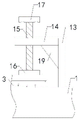
FIG. 2 is an enlarged schematic view of the connection of the second connecting plate with the third connecting plate, etc.;
FIG. 3 is an enlarged schematic view of the connection of the fourth connecting plate with the fifth connecting plate, etc.;
FIG. 4 is an enlarged view of the sealing cap attached to a handle or the like;
in the drawings, the reference numbers: 1. a work table; 2. a first connecting rod; 3. a base plate; 4. a first connecting plate; 5. a second connecting rod; 6. a hydraulic cylinder; 7. cutting a working head; 8. a second connecting plate; 9. a third connecting plate; 10. a first threaded rod; 11. a first fixing plate; 12. a first handle; 13. a fourth connecting plate; 14. a fifth connecting plate; 15. a second threaded rod; 16. a second fixing plate; 17. a second handle; 18. a first reinforcing plate; 19. a second reinforcing plate; 20. cushion blocks; 21. a storage box; 22. a rack; 23. a sealing cover; 24. a screw; 25. a handle; 26. a caster wheel; 27. and (6) pushing the hand.
Detailed Description
The following detailed description of the embodiments of the present invention is provided with reference to the accompanying drawings and examples. The following examples are intended to illustrate the invention, but are not intended to limit the scope of the invention.
As shown in fig. 1 to 4, the utility model discloses a plate shearing machine, including workstation 1, backing plate 3, first connecting plate 4 and pneumatic cylinder 6, the left front side, the left rear side, the right front side and the right rear side of workstation 1 bottom all are provided with first connecting rod 2, the bottom of backing plate 3 is connected with the top of workstation 1, the left front side, the left rear side, the right front side and the right rear side of first connecting plate 4 bottom all are provided with second connecting rod 5, the bottom of four groups of second connecting rod 5 is connected with the left front side, the left rear side, the right front side and the right rear side of workstation 1 top respectively, the top of pneumatic cylinder 6 is connected with the bottom of first connecting plate 4, the bottom of pneumatic cylinder 6 is provided with tailors working head 7; the novel workbench is characterized by further comprising a second connecting plate 8, a third connecting plate 9, a first threaded rod 10, a fourth connecting plate 13, a fifth connecting plate 14, a second threaded rod 15, a first reinforcing plate 18 and a second reinforcing plate 19, wherein the bottom end of the second connecting plate 8 is connected with the left side of the top end of the workbench 1, the left end of the third connecting plate 9 is connected with the upper side of the right end of the second connecting plate 8, a first threaded hole is formed in the third connecting plate 9, the bottom end of the first threaded rod 10 is inserted into the first threaded hole of the third connecting plate 9 in a threaded manner, a first fixing plate 11 is arranged at the bottom end of the first threaded rod 10, a first handle 12 is arranged at the top end of the first threaded rod 10, the bottom end of the fourth connecting plate 13 is connected with the right side of the top end of the workbench 1, the right end of the fifth connecting plate 14 is connected with the upper side of the left end of the fourth connecting plate 13, a second threaded hole is formed in the fifth connecting plate, a second fixing plate 16 is arranged at the bottom end of the second threaded rod 15, and a second handle 17 is arranged at the top end of the second threaded rod 15; through rotating first handle, make the bottom of first fixed plate and the top left side of panel paste tightly, then rotate the second handle, make the bottom of second fixed plate and the top right side of panel paste tightly, effectively fixed panel under the effect of first fixed plate and second fixed plate prevents that panel from taking place to deviate at the in-process that cuts, improves stability in use.
The utility model discloses a plate shearing machine, still include first reinforcing plate 18 and second reinforcing plate 19, the left end of first reinforcing plate 18 is connected with the right-hand member of second connecting plate 8, the top of first reinforcing plate 18 is connected with the bottom of third connecting plate 9, the right-hand member of second reinforcing plate 19 is connected with the left end of fourth connecting plate 13, the top of second reinforcing plate 19 is connected with the bottom of fifth connecting plate 14; through setting up first reinforcing plate and second reinforcing plate, strengthen the support to third connecting plate and fifth connecting plate, improve stability in use.
In the plate shearing machine of the utility model, the bottom ends of the four groups of the first connecting rods 2 are provided with the cushion blocks 20; through setting up four groups of cushion, increase the contact surface with ground, improve stability in use.
The utility model discloses a plate shearing machine, still include containing box 21, the inside of containing box 21 is provided with the cavity, the left end of cavity is provided with the access hole, and the access hole communicates with each other with the cavity, the bottom of cavity is provided with supporter 22; through setting up containing box and supporter, be convenient for accomodate the panel of accomplishing the tailorring, improve the convenience in use.
The utility model discloses a plate shearing machine, still include the screw 24, the left end of the taking-in and putting-out opening of the containing box 21 is provided with the sealing cover 23, the sealing cover 23 is connected with the left end of the containing box 21 through the screw 24; through setting up sealed lid and screw, play sealed effect to the cavity of containing box, prevent that external dust from getting into the cavity of containing box from putting the mouth in, improve the practicality.
In the plate shearing machine of the utility model, the left end of the sealing cover 23 is provided with a handle 25; through setting up the handle, conveniently open sealed lid, improve the convenience of use.
In the plate shearing machine of the utility model, the left front side, the left rear side, the right front side and the right rear side of the bottom end of the containing box 21 are all provided with the caster 26; through setting up four truckles of group, be convenient for remove containing box to assigned position, improve the practicality.
The utility model relates to a plate shearing machine, a push handle 27 is arranged on the upper side of the right end of a containing box 21; through setting up the pushing hands, be convenient for promote the containing box and remove, improve the convenience in use.
The utility model discloses a plate shearing machine, it is at the during operation, at first arranges the top of backing plate in with panel, then rotates first handle, makes the bottom of first fixed plate and the top left side of panel paste tightly, later rotates the second handle, makes the bottom of second fixed plate and the top right side of panel paste tightly, effectively fixes panel under the effect of first fixed plate and second fixed plate, then the pneumatic cylinder drives and tailors the working head and descend, tailor to panel can.
The utility model discloses a plate shearing machine, its mounting means, connected mode or mode of setting are common mechanical system, as long as can reach all can implement of its beneficial effect.
The foregoing is only a preferred embodiment of the present invention, and it should be noted that, for those skilled in the art, a plurality of modifications and variations can be made without departing from the technical principle of the present invention, and these modifications and variations should also be regarded as the protection scope of the present invention.
Claims (8)
1. A plate shearing machine comprises a workbench (1), a backing plate (3), a first connecting plate (4) and hydraulic cylinders (6), wherein the left front side, the left rear side, the right front side and the right rear side of the bottom end of the workbench (1) are respectively provided with a first connecting rod (2), the bottom end of the backing plate (3) is connected with the top end of the workbench (1), the left front side, the left rear side, the right front side and the right rear side of the bottom end of the first connecting plate (4) are respectively provided with a second connecting rod (5), the bottoms of the four groups of second connecting rods (5) are respectively connected with the left front side, the left rear side, the right front side and the right rear side of the top end of the workbench (1), the top end of each hydraulic cylinder (6) is connected with the bottom end of the first connecting plate (4), and the bottom end of each hydraulic cylinder (6) is provided with; the novel workbench is characterized by further comprising a second connecting plate (8), a third connecting plate (9), a first threaded rod (10), a fourth connecting plate (13), a fifth connecting plate (14), a second threaded rod (15), a first reinforcing plate (18) and a second reinforcing plate (19), wherein the bottom end of the second connecting plate (8) is connected with the left side of the top end of the workbench (1), the left end of the third connecting plate (9) is connected with the upper side of the right end of the second connecting plate (8), the third connecting plate (9) is provided with a first threaded hole, the bottom end of the first threaded rod (10) is inserted into the first threaded hole of the third connecting plate (9) in a screw manner, the bottom end of the first threaded rod (10) is provided with a first fixing plate (11), the top end of the first threaded rod (10) is provided with a first handle (12), the bottom end of the fourth connecting plate (13) is connected with the right side of the top end of the workbench (1), and the right end of the fifth connecting plate (14) is connected with the upper side, a second threaded hole is formed in the fifth connecting plate (14), the bottom end of the second threaded rod (15) is inserted into the second threaded hole of the fifth connecting plate (14) in a threaded mode, a second fixing plate (16) is arranged at the bottom end of the second threaded rod (15), and a second handle (17) is arranged at the top end of the second threaded rod (15).
2. The plate shearing machine as claimed in claim 1, characterized in that it further comprises a first reinforcing plate (18) and a second reinforcing plate (19), the left end of the first reinforcing plate (18) being connected to the right end of the second connecting plate (8), the top end of the first reinforcing plate (18) being connected to the bottom end of the third connecting plate (9), the right end of the second reinforcing plate (19) being connected to the left end of the fourth connecting plate (13), the top end of the second reinforcing plate (19) being connected to the bottom end of the fifth connecting plate (14).
3. A plate shearing machine as claimed in claim 2, characterized in that the bottom ends of the four groups of first connecting rods (2) are provided with spacers (20).
4. The plate shearing machine according to claim 3, characterized in that, further comprises a containing box (21), a cavity is arranged inside the containing box (21), a taking and placing opening is arranged at the left end of the cavity, the taking and placing opening is communicated with the cavity, and a shelf (22) is arranged at the bottom end of the cavity.
5. The plate shearing machine according to claim 4, characterized in that it further comprises a screw (24), a sealing cover (23) is arranged at the left end of the access opening of the receiving box (21), and the sealing cover (23) is connected with the left end of the receiving box (21) through the screw (24).
6. The plate shearing machine as claimed in claim 5, characterized in that the left end of the sealing cover (23) is provided with a handle (25).
7. The plate shearing machine as claimed in claim 6, characterized in that the left front side, the left rear side, the right front side and the right rear side of the bottom end of the container box (21) are provided with casters (26).
8. The plate shearing machine as claimed in claim 7, characterized in that the right end of the container (21) is provided at its upper side with a push handle (27).
Priority Applications (1)
| Application Number | Priority Date | Filing Date | Title |
|---|---|---|---|
| CN201921875163.9U CN210587428U (en) | 2019-11-01 | 2019-11-01 | Plate shearing machine |
Applications Claiming Priority (1)
| Application Number | Priority Date | Filing Date | Title |
|---|---|---|---|
| CN201921875163.9U CN210587428U (en) | 2019-11-01 | 2019-11-01 | Plate shearing machine |
Publications (1)
| Publication Number | Publication Date |
|---|---|
| CN210587428U true CN210587428U (en) | 2020-05-22 |
Family
ID=70712851
Family Applications (1)
| Application Number | Title | Priority Date | Filing Date |
|---|---|---|---|
| CN201921875163.9U Active CN210587428U (en) | 2019-11-01 | 2019-11-01 | Plate shearing machine |
Country Status (1)
| Country | Link |
|---|---|
| CN (1) | CN210587428U (en) |
-
2019
- 2019-11-01 CN CN201921875163.9U patent/CN210587428U/en active Active
Similar Documents
| Publication | Publication Date | Title |
|---|---|---|
| CN210587428U (en) | Plate shearing machine | |
| CN211306266U (en) | Cutter strorage device for precision finishing | |
| CN211104138U (en) | Carton board pressing edge forming cutting machine | |
| CN212046173U (en) | Cutting equipment is used in wrapping bag processing | |
| CN211761724U (en) | Plastic composite film cutting device | |
| CN210835888U (en) | Dustproof computer mainframe | |
| CN212021094U (en) | Edge banding machine with limiting function for furniture processing | |
| CN211894270U (en) | Portable plastic uptake box for packaging | |
| CN214216345U (en) | Automatic opening flanging device for material packaging bag | |
| CN211515713U (en) | Metal plate forming machine | |
| CN210233217U (en) | Plastic film perforating device | |
| CN212825193U (en) | End sealing machine for industrial aerosol can production | |
| CN209774610U (en) | Adjustable tooling frame for router | |
| CN210586517U (en) | Fingerprint sampler shell former | |
| CN210172264U (en) | Bending device of engineering machinery cab framework | |
| CN212372293U (en) | Efficient hose cutting machine | |
| CN209940442U (en) | Feeding mechanism of under-cover filling machine | |
| CN210235519U (en) | Flower packing seals cutting device | |
| CN214869019U (en) | Adjustable steel drum cutting equipment | |
| CN218488021U (en) | Precision grinding apparatus is with grinding mold core processingequipment | |
| CN220054213U (en) | Automatic weighing and packaging device for auxiliary agent finished products | |
| CN214127702U (en) | Multifunctional identification engineering design platform | |
| CN214002527U (en) | Portable porcelain product packaging box | |
| CN214821264U (en) | Blank pressing device for production and processing of packaging boxes | |
| CN211033243U (en) | A pedal capper for moulding mirror production and processing of cornea |
Legal Events
| Date | Code | Title | Description |
|---|---|---|---|
| GR01 | Patent grant | ||
| GR01 | Patent grant |