CN210587266U - Distance drill for shielding C-shaped sealing ring on upper part of main pump - Google Patents
Distance drill for shielding C-shaped sealing ring on upper part of main pump Download PDFInfo
- Publication number
- CN210587266U CN210587266U CN201921406157.9U CN201921406157U CN210587266U CN 210587266 U CN210587266 U CN 210587266U CN 201921406157 U CN201921406157 U CN 201921406157U CN 210587266 U CN210587266 U CN 210587266U
- Authority
- CN
- China
- Prior art keywords
- drill
- sealing ring
- drill chuck
- inclined rod
- shaped sealing
- Prior art date
- Legal status (The legal status is an assumption and is not a legal conclusion. Google has not performed a legal analysis and makes no representation as to the accuracy of the status listed.)
- Active
Links
Images


Abstract
A distance drill for a C-shaped sealing ring on the upper part of a shielding main pump belongs to the technical field of maintenance of the shielding main pump of a nuclear power station. The distance drill comprises a drill bit, a drill chuck, a pistol drill and a supporting mechanism; the drill bit penetrates through the drill chuck, the head end of the drill bit is used for abutting against the upper C-shaped sealing ring to drill a hole, and the tail end of the drill bit is connected with the drill chuck of the pistol drill through the fixing ring; the front part of the drill chuck is designed with an intersecting line shape consistent with the upper C-shaped sealing ring, and the drill chuck is provided with a liquid discharge hole communicated with a drill bit passing through a channel; the supporting mechanism is used for supporting between two main bolts of the shielding main pump and applying pressure to the drill chuck, so that the drill chuck can be tightly attached to the upper C-shaped sealing ring. The utility model discloses can realize location and distance drilling on the C type sealing ring in the operation in the narrow and small region of main pump upper portion C type sealing ring to the smear metal that prevents the drilling production gets into inside the main pump.
Description
Technical Field
The utility model belongs to the technical field of the maintenance of nuclear power station shielding formula main pump, under concretely relates to high radioactivity environment, can dismantle between part and pump case welded upper portion C type sealing ring before cutting shielding main pump, drill and carry out the distance of dredging the radioactivity raffinate to upper portion C type sealing ring and bore.
Background
After the nuclear power station runs for a long time, the possibility that other parts such as a main pump thrust bearing, a shielding sleeve and the like go wrong is gradually increased, so that the maintenance process is reasonably optimized and a special maintenance tool is developed to realize the overall replacement of the shielding main pump in a high-radioactivity environment.
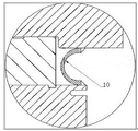
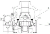
The upper C-ring seal is an annular part welded between the main pump housing and the removable main pump assembly, with an inner diameter of 1599.18mm, which is the pressure boundary of the main pump. As shown in figure 1, the cross section is C-shaped, the thickness of both ends is 11.17mm, the thickness of the middle part is 6.35mm, the total height is 85.09mm, and the material is ASME SA-182F 304N. In the process of the whole replacement of the shielding main pump, firstly, the detachable main pump assembly needs to be removed from the pump shell, the upper C-shaped sealing ring needs to be cut, however, due to the structural characteristics of the shielding main pump, after the internal medium of the shielding main pump is drained through the lower drain valve, 40L of radioactive liquid still exists in the rear cavity area of the upper C-shaped sealing ring (such as A, B in fig. 2), and radioactive residual liquid splashes along the cutting seam when the upper C-shaped sealing ring is cut, so that field workers and equipment are contaminated. Therefore, a special device is needed to be designed for draining the radioactive residual liquid in the upper C-shaped sealing ring.
The difficult point that the interior raffinate of upper portion C type seal ring was dredged and is arranged has in combination shielding main pump's structural feature and on-the-spot arrangement condition: the radioactive residual liquid is difficult to collect, the device and the upper C-shaped sealing ring are difficult to seal, the drilling difficulty on the upper C-shaped sealing ring is large, the operation space is narrow, the foreign matter control difficulty and the evacuation progress pressure are large.
Chinese patent application CN201711270906.5 discloses a nuclear power is with shielding main pump Canopy seal ring drilling flow thinning device to specifically disclose flow thinning device includes the bottom plate, be equipped with the seal valve piece that can be at the horizontal direction back-and-forth movement on the bottom plate, be equipped with the ball valve in the seal valve piece, be equipped with the flowing back passageway on the seal valve piece, the front end of seal valve piece is equipped with sealed briquetting, the shape and Canopy seal ring appearance looks adaptation of sealed briquetting, sealed briquetting is opened along the fore-and-aft direction has the water conservancy diversion hole, be equipped with the drilling equipment at seal valve piece rear on the bottom plate, drilling equipment includes feed mechanism and installs the drill bit on feed mechanism, the drill bit can loop through ball valve, flowing back pipeline and water conservancy diversion hole. Although the drilling flow dredging device can realize the drilling flow dredging of the Canopy sealing ring and prevent the coolant from splashing, the drilling operation process is not labor-saving enough.
SUMMERY OF THE UTILITY MODEL
The utility model discloses to the problem that prior art exists, provided a distance that shielding main pump upper portion C type sealing ring was used and bored, can be in the operation of main pump upper portion C type sealing ring narrow and small region, realize location and distance drilling on the C type sealing ring, can effectively collect, dredge the radioactive raffinate that flows.
The utility model discloses a can realize through following technical scheme:
the utility model provides a distance drill for shielding a C-shaped sealing ring on the upper part of a main pump, which comprises a drill bit, a drill clamp, a pistol drill and a supporting mechanism; the drill bit penetrates through the drill chuck, the head end of the drill bit is used for abutting against the upper C-shaped sealing ring to drill a hole, and the tail end of the drill bit is connected with the drill chuck of the pistol drill through the fixing ring; the front part of the drill chuck is designed with an intersecting line shape consistent with the upper C-shaped sealing ring, and the drill chuck is provided with a liquid discharge hole communicated with a drill bit passing through a channel; the supporting mechanism is used for supporting between two main bolts of the shielding main pump and applying pressure to the drill chuck, so that the drill chuck can be tightly attached to the upper C-shaped sealing ring.
The distance drill and the upper C-shaped sealing ring are reliably sealed, and the radioactive residual liquid can be effectively cut under the condition of ensuring that the radioactive residual liquid does not leak.
Preferably, the drill chuck comprises a drill chuck front cover and a drill chuck rear cover; and an irradiation-resistant sealing gasket is arranged between the drill chuck front cover and the drill chuck rear cover and is fastened through screws.
Preferably, the drill chuck front cover is provided with a first guide hole, the drill chuck rear cover is provided with a second guide hole, the axes of the first guide hole and the second guide hole pass through the middle part of the upper C-shaped sealing ring and are perpendicular to a drilling point tangent plane, and the first guide hole and the second guide hole are used for guiding the drill bit to pass through the drill chuck.
Preferably, a circle of groove is arranged at the front part of the drill chuck around the open hole, and a radiation-resistant sealing ring is arranged in the groove.
Preferably, the back part of the drill chuck is provided with a framework oil seal for preventing residual liquid from leaking between the drill chuck and the drill bit.
Preferably, a drilling and clamping cavity is arranged between the first guide hole and the second guide hole, and the diameter of the drilling and clamping cavity is larger than that of the first guide hole or the second guide hole.
Preferably, the support mechanism comprises a first long inclined rod, a second long inclined rod, a first short inclined rod, a second short inclined rod, a first support claw, a second support claw, a support slider, a locking handle, an eyebolt and an optical axis bolt nut; the supporting slide block is provided with a guide groove for accommodating the drill chuck rear cover; one end of the first long inclined rod is connected with the drill chuck, the other end of the first long inclined rod is connected with the first supporting claw, one end of the first short inclined rod is connected with the supporting sliding block, and the other end of the first short inclined rod is connected with the first supporting claw; one end of the second long inclined rod is connected with the drill chuck, the other end of the second long inclined rod is connected with the second supporting claw, one end of the second short inclined rod is connected with the supporting sliding block, and the other end of the second short inclined rod is connected with the second supporting claw; the first supporting claw and the second supporting claw are used for being respectively supported on the two main bolts; the lifting bolt is connected with the drill chuck through the optical axis bolt nut, and the relative displacement between the locking handle and the lifting bolt is adjusted through rotating the locking handle arranged at the tail end of the lifting bolt, so that the supporting slide block moves along the radial direction.
Preferably, the curvature radius of the matched gripping surface of the first supporting claw and the second supporting claw with the main bolt is consistent with the radius of the section circle of the main bolt.
Preferably, rubber pads are arranged on the grabbing surfaces of the first supporting claw and the second supporting claw, which are matched with the main bolt respectively.
Preferably, the center of a rotating shaft of the first supporting claw and the first long inclined rod or the center of a rotating shaft of the second supporting claw and the second long inclined rod is B, the center of a circle of the cross section of the main bolt is O, the center of a rotating shaft of the first long inclined rod and the drill chuck or the center of a rotating shaft of the second long inclined rod and the drill chuck is A, the center of a rotating shaft of the first supporting claw and the first short inclined rod or the center of a rotating shaft of the second supporting claw and the second short inclined rod is C, the center of a rotating shaft of the first short inclined rod and the supporting slide block or the center of a rotating shaft of the second short inclined rod and the supporting slide block is D, a passing point C is a perpendicular line of the line segment AD, and the intersection point of the perpendicular line and the line segment AD is E; the length relation on the same main bolt side satisfies: the sum of the lengths of the line segment AB and the line segment BO is greater than the length of the line segment AO, and the length of the line segment CD is greater than the length of the line segment CE.
The utility model discloses following beneficial effect has:
the utility model relates to a distance that shielding main pump upper portion C type sealing ring was used is bored, can realize location and distance drilling on the C type sealing ring in the operation of main pump upper portion C type sealing ring narrow and small region to inside the smear metal that prevents the drilling production got into the main pump, there was reliable sealed between device and upper portion C type sealing ring, carry out effectual containing and collection to the radioactivity raffinate of outflow.
Drawings
FIG. 1 is a cross-sectional view of a prior art top C-ring seal;
FIG. 2 is a schematic representation of a prior art radioactive raffinate in an upper C-ring seal;
FIG. 3 is a schematic structural view of a distance drill for shielding a C-shaped sealing ring at the upper part of a main pump according to the present invention;
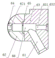
FIG. 4 is a cross-sectional view of the drill chuck of FIG. 3;
FIG. 5 is an assembled view of the distance drill of FIG. 3 mounted on the upper C-ring seal;
FIG. 6 is a schematic view of the support mechanism of FIG. 3;
FIG. 7 is a block diagram of the radioactive residual liquid drainage device in the C-shaped sealing ring at the upper part of the shielded main pump with the distance drill in FIG. 3.
Detailed Description
The following are specific embodiments of the present invention and the accompanying drawings are used to further describe the technical solution of the present invention, but the present invention is not limited to these embodiments.
Referring to fig. 3-5, a distance drill for shielding the upper C-ring seal of the main pump comprises a drill bit 5, a drill chuck 6, a pistol drill 9 and a support mechanism 7. The drill bit 5 penetrates through the drill chuck 6, the head end of the drill bit 5 is used for abutting against the upper C-shaped sealing ring 10 to drill, and the tail end of the drill bit 5 is used for being connected with a drill chuck of a pistol drill 9 through a fixing ring 8. The front part of the drill chuck 6 is designed with an intersecting line shape consistent with the upper C-shaped sealing ring, and the drill chuck 6 is provided with a liquid discharge hole 61 communicated with a drill bit passing channel. The supporting mechanism 7 is used for supporting between two main bolts 20 of the shielding main pump and pressing the drill clamp 6, so that the drill clamp 6 can be tightly attached to the upper C-shaped sealing ring 10. Once the drill bit drills through the C-ring, the radioactive raffinate can drain through the drain hole 61 of the distance drill.
The drill chuck 6 comprises a front chuck cover 62 and a rear chuck cover 63. An irradiation-resistant sealing gasket 65 such as an ethylene propylene diene monomer sealing gasket is arranged between the drill chuck front cover 62 and the drill chuck rear cover 63, and the sealing is realized through the fastening of screws. The front part of the drill chuck 6, namely a front cover 62 of the drill chuck, is provided with a circle of grooves around the open hole, and the grooves are internally provided with an irradiation-resistant sealing ring 64, such as an O-shaped ring made of ethylene propylene diene monomer, the interface diameter of the O-shaped ring is larger, so that enough deformation and sealing area are ensured, and residual liquid cannot leak from the upper C-shaped sealing ring when the drill chuck is tightly attached to the upper C-shaped sealing ring. The drill chuck front cover 62 is provided with a first guide hole 621, the drill chuck rear cover 63 is provided with a second guide hole 631, the first guide hole 621 with the diameter of the second guide hole 631 all matches with the drill bit diameter, the first guide hole 621 with the second guide hole 631 is used for guiding the drill bit 5 passes through the drill chuck 6, the first guide hole 621 with the axis of the second guide hole 631 passes through the middle of the upper C-shaped sealing ring and is perpendicular to the drilling point tangent plane, so that the drill chuck can drill a hole in the middle of the sealing ring without drilling deviation when tightly attaching to the upper C-shaped sealing ring. The back of the drill chuck, i.e. the back cover of the drill chuck, is provided with a skeleton oil seal 632 for preventing residual liquid from leaking between the drill chuck 6 and the drill bit 5. The cutting scraps of the stainless steel are not easy to cut off, the coiled materials are wound on the drill rod, in order to prevent the liquid drainage hole 61 from being blocked, a drilling clamp cavity 66 is arranged between the first guide hole and the second guide hole, and the diameter of the cavity is larger than that of the first guide hole or the second guide hole.
The supporting mechanism 7 is used for applying pressure to the drill chuck 6 by supporting two adjacent main bolts 20 of the drill hole, so that the drill chuck can be ensured to be tightly attached to the upper C-shaped sealing ring 10. In order to facilitate the disassembly and assembly and have the self-adaptability, the supporting mechanism 7 comprises a first long inclined rod 71, a second long inclined rod 72, a first short inclined rod 73, a second short inclined rod 74, a first supporting claw 75, a second supporting claw 76, a supporting slide block 77, a locking handle 78, an eyebolt 79 and an optical axis bolt nut 80. The supporting slide block is provided with a guide groove for accommodating the drill chuck rear cover. The two sides of the drill chuck rear cover are retracted inwards relative to the drill chuck front cover, the supporting slide block can move along the radial direction of the drill chuck rear cover under the constraint of the guide groove, and when the drill chuck rear cover moves to the position of the drill chuck front cover, the supporting slide block cannot move forwards under the limitation of the bottom of the drill chuck front cover. One end of the first long inclined rod 71 is connected to the drill chuck 6, the other end of the first long inclined rod is connected to the first supporting claw 75, one end of the first short inclined rod 73 is connected to the supporting slide block 77, and the other end of the first short inclined rod is connected to the first supporting claw 75. One end of the second long inclined rod 72 is connected to the drill chuck 6, the other end of the second long inclined rod is connected to the second support claw 76, one end of the second short inclined rod 72 is connected to the support sliding block 77, and the other end of the second short inclined rod is connected to the second support claw 76. The first supporting claw 75 and the second supporting claw 76 are used for being supported on two main bolts respectively. The first long diagonal bar 71, the second long diagonal bar 72, the first short diagonal bar 73, and the second short diagonal bar 74 form a symmetrical quadrilateral configuration with the support slider 77 as a center. The lifting eye screw 79 is connected with the drill chuck 6 through the optical axis bolt nut 80, and the relative displacement between the locking handle 78 and the lifting eye screw 79 is adjusted by rotating the locking handle 78 arranged at the tail end of the lifting eye screw, so that the supporting slide block 77 moves along the radial direction.
In order to protect the main bolt 20, the curvature radius of the gripping surface of the first supporting claw 75 and the second supporting claw 76 is consistent with the radius of the section circle of the main bolt, and rubber pads are arranged. Because of the drill chuck and autogenous structural limitations, the support slide 77 can only move horizontally in the radial direction. As shown in fig. 6, the center of the rotation axis of the first supporting claw 75 and the first long diagonal bar 71 is B, the center of the cross-section circle of the main bolt 20 is O, the center of the rotation axis of the first long diagonal bar 71 and the drill chuck 6 is a, the center of the rotation axis of the first supporting claw 75 and the first short diagonal bar 73 is C, the center of the rotation axis of the first short diagonal bar 74 and the supporting slider 77 is D, the crossing point C is a perpendicular line of the line segment AD, and the intersection point of the perpendicular line and the line segment AD is E. The length relation of the main bolt on the left side satisfies: the sum of the lengths of the line segment AB and the line segment BO is greater than the length of the line segment AO, and the length of the line segment CD is greater than the length of the line segment CE. Similarly, the center of the rotating shaft of the second support claw 76 and the second long oblique rod 72 is B, the center of the cross section circle of the main bolt 20 is O, the center of the rotating shaft of the second long oblique rod 72 and the drill chuck 6 is a, the center of the rotating shaft of the second support claw 76 and the second short oblique rod 74 is C, the center of the rotating shaft of the second short oblique rod 74 and the support slider is D, the passing point C is a perpendicular line of the line segment AD, and the intersection point of the perpendicular line and the line segment AD is E; the length relation of the main bolt on the right side meets the following conditions: the sum of the lengths of the line segment AB and the line segment BO is greater than the length of the line segment AO, and the length of the line segment CD is greater than the length of the line segment CE.
The supporting slide block 77 is moved towards the upper C-shaped sealing ring 10, the supporting slide block 77 cannot move, the supporting claws 75 and 76 cannot move, the locking handle 78 is rotated, the eyebolt can rotate around the optical axis bolt, a pretightening force is applied to the supporting slide block 77 by utilizing the relative displacement of the locking handle 78 and the eyebolt 79, the supporting mechanism applies an acting force to the main bolt 20, the main bolt 20 has a reaction force to the supporting mechanism, a certain pressure is applied to a drill chuck, the more the locking handle 78 rotates, the greater the force applied to the drill chuck is, and the tighter the distance drill is clamped between the upper C-shaped sealing ring and two adjacent main bolts. When the support mechanism supports the main bolt, the lifting bolt is in a horizontal position. When the evacuation is finished, the locking handle 78 is rotated in the opposite direction, and the supporting slide block 77 is moved outwards to complete the removal of the distance drill. The eye screw 79 is connected to the drill chuck by means of a plain bolt nut 80, and can rotate around the plain bolt, and when the support mechanism is withdrawn, the eye screw is in a downward inclined position to avoid interference of the locking handle 78 with the withdrawn support slider 77.
Referring to fig. 7, the radioactive residual liquid drainage device in the C-shaped sealing ring at the upper part of the shielded main pump comprises the distance drill 1, a vacuum waste liquid tank 2, a filter 3 and a vacuum pump 4. The distance drill 1 is positioned on the upper C-shaped sealing ring and used for distance drilling. The liquid discharge hole of the distance drill 1 is connected with the vacuum waste liquid tank 2 through a pipeline, and the vacuum waste liquid tank 2 is sequentially connected with the filter 3 and the vacuum pump 4 through pipelines.
The vacuum pump 4 is started to pump the interior of the device into negative pressure, so that liquid can be effectively prevented from leaking at the joint, and in the moment that the sealing ring is drilled through, cuttings can be sucked into the dredging device to be prevented from entering the main pump, and residual liquid can be sucked out quickly under the action of front-back pressure difference, so that the dredging efficiency is improved. The filter 3 is used to adsorb the radioactive gas in the device and prevent air pollution in the working area. The vacuum waste liquid tank 2 is used for collecting radioactive residual liquid and cutting scraps, and is convenient for subsequent unified treatment. The distance drill 1 is positioned and provided with a distance hole on the upper C-shaped sealing ring, and the radioactive residual liquid and cuttings flowing out are contained and sealed by utilizing the structure of the distance drill, so that the contamination of personnel and equipment is prevented. For the aspect of observing the evacuation condition of raffinate and guaranteeing that the pipeline can not be inhaled and held back, the connecting tube adopts transparent PVC steel wire hose between the equipment. The hose is connected with the joint of each device through a hose clamp, so that the hose is convenient to assemble and disassemble.
The vacuum waste liquid tank is made of single-layer 304 stainless steel, and in view of radiation protection, collected liquid is discharged to a nearby floor drain as soon as possible after residual liquid in the upper C-shaped sealing ring is drained, so that a drain valve is designed at the lower part of the tank body, universal brake nylon wheels are designed on supporting legs, movement and positioning on the ground are facilitated, handles are symmetrically arranged on two sides of the tank body, and the vacuum waste liquid tank is convenient to carry when going upstairs and downstairs. Still be provided with the glass liquid level window on the jar body, have the liquid level scale mark on the window for observe the volume of collecting liquid and whether because of the liquid boiling condition that the jar internal pressure crossed the cause excessively. In order to effectively prevent residual liquid from being sucked into the air filter, the water pumping port and the air exhaust port are arranged at the top of the tank body, and in addition, isolation valves are arranged on the inlet and outlet pipelines, so that the waste liquid tank is conveniently isolated from the dredging device. The vacuum gauge is arranged at the top of the waste liquid tank, so that the vacuum degree in the tank can be conveniently monitored in real time. For guaranteeing the gas tightness of the waste liquid tank, the tank body is convenient to clean, and the tank cover and the tank body are designed to be connected through a stainless steel vacuum clamp.
The filter is designed to comprise a first steel tank filled with soda lime and a second steel tank filled with activated carbon; the vacuum waste liquid tank is connected with the bottom of the first steel tank through a pipeline, the side wall of the first steel tank is connected with the bottom of the second steel tank through a pipeline, and the side wall of the second steel tank is connected with the vacuum pump through a pipeline. The first steel tank and the second steel tank are 304 stainless steel tanks, and are erected on the ground by using 304 stainless steel frames, and the stainless steel frames are used for fixing the steel tanks and facilitating integral movement. The tank cover is connected with the tank body through a stainless steel vacuum clamp, so that the air sealing of the tank body can be ensured, and the filling and the replacement of the activated carbon and the soda lime are facilitated. In order to ensure the full contact of the sucked mixed gas with the soda lime and the activated carbon and improve the filtering effect, the process is designed in such a way that the mixed gas firstly enters from the bottom of a steel tank filled with the soda lime, flows out from the side wall, the moisture in the gas is filtered, then enters from the bottom of the steel tank filled with the activated carbon, flows out from the side wall, and the radioactive gas in the gas is filtered.
The vacuum pump is designed to be a jet vacuum pump with small volume, light weight, high reliability and simple maintenance.
The specific operation principle is as follows: according to the actual situation of a site, a distance drill (a dismantled pistol drill) is erected between two adjacent main bolts, the distance drill and an upper C-shaped sealing ring are confirmed to be well sealed, then the head of a drill bit is abutted against the upper C-shaped sealing ring, and a fixing ring is fixed at the corresponding position of a drill rod according to the moving distance required. The four devices are correctly connected in the order of distance drill, vacuum waste liquid tank, air filter and vacuum pump. Starting the vacuum pump, confirming that the interior of the device has become negative pressure and the vacuum degree is not changed through a vacuum meter on the vacuum waste liquid tank, connecting the pistol drill with the drill bit, setting the pistol drill at a lower rotating speed (about 100 plus 200 revolutions per minute), starting the pistol drill to drill, keeping the process stable and stabilizing the direction, and reducing the pressure and preventing the drill bit from being damaged when the upper C-shaped sealing ring is about to be drilled through. When the drill bit needs to be replaced in drilling, the negative pressure in the device is firstly confirmed, and the framework sealing is carefully damaged when the drill bit is pulled out. After drilling through the upper C-shaped sealing ring, the flowing condition of liquid in the pipeline and the liquid level height in the vacuum waste liquid tank are observed, and if the liquid in the tank is found to be overturned, a valve of the small exhaust port needs to be closed. When no liquid flows in the observation pipeline, the distance drill on the device is removed, a hose for suction is connected with the pipeline, and the distance drill is inserted into the C-shaped ring drill hole at the upper part to continuously suck the radioactive residual liquid below the height of the drill hole. After the residual liquid is completely absorbed, the valves of the water inlet and the exhaust port of the vacuum waste liquid tank are closed, and then the vacuum pump is closed.
It will be understood by those skilled in the art that the embodiments of the present invention as described above and shown in the drawings are given by way of example only and are not limiting of the present invention. The purpose of the utility model is completely and effectively realized. The functional and structural principles of the present invention have been shown and described in the embodiments without departing from the principles, embodiments of the present invention may have any deformation or modification.
Claims (10)
1. A distance drill for shielding a C-shaped sealing ring on the upper part of a main pump is characterized by comprising a drill bit, a drill chuck, a pistol drill and a supporting mechanism; the drill bit penetrates through the drill chuck, the head end of the drill bit is used for abutting against the upper C-shaped sealing ring to drill a hole, and the tail end of the drill bit is connected with the drill chuck of the pistol drill through the fixing ring; the front part of the drill chuck is designed with an intersecting line shape consistent with the upper C-shaped sealing ring, and the drill chuck is provided with a liquid discharge hole communicated with a drill bit passing through a channel; the supporting mechanism is used for supporting between two main bolts of the shielding main pump and applying pressure to the drill chuck, so that the drill chuck can be tightly attached to the upper C-shaped sealing ring.
2. The distance drill for shielding the C-shaped sealing ring at the upper part of the main pump as claimed in claim 1, wherein the drill chuck comprises a drill chuck front cover and a drill chuck rear cover; and an irradiation-resistant sealing gasket is arranged between the drill chuck front cover and the drill chuck rear cover and is fastened through screws.
3. The distance drill for shielding the upper C-shaped sealing ring of the main pump as claimed in claim 2, wherein a first guide hole is formed in the front cover of the drill chuck, a second guide hole is formed in the rear cover of the drill chuck, the axis of the first guide hole and the axis of the second guide hole pass through the middle of the upper C-shaped sealing ring and are perpendicular to a cutting plane of a drill point, and the first guide hole and the second guide hole are used for guiding the drill bit to penetrate through the drill chuck.
4. The distance drill for shielding the C-shaped sealing ring at the upper part of the main pump as claimed in claim 1, wherein a circle of groove is arranged at the front part of the drill chuck around the opening, and a radiation-resistant sealing ring is arranged in the groove.
5. The distance drill for shielding the C-shaped sealing ring at the upper part of the main pump as claimed in claim 1, wherein a skeleton oil seal is arranged at the rear part of the drill chuck for preventing residual liquid from leaking between the drill chuck and a drill bit.
6. The distance drill for shielding the upper C-shaped sealing ring of the main pump according to claim 3, wherein a drill holder cavity is arranged between the first guide hole and the second guide hole, and the diameter of the drill holder cavity is larger than that of the first guide hole or the second guide hole.
7. The distance drill for shielding the C-shaped sealing ring at the upper part of the main pump according to claim 1, wherein the supporting mechanism comprises a first long inclined rod, a second long inclined rod, a first short inclined rod, a second short inclined rod, a first supporting claw, a second supporting claw, a supporting sliding block, a locking handle, an eyebolt and a plain shaft bolt nut; the supporting slide block is provided with a guide groove for accommodating the drill chuck rear cover; one end of the first long inclined rod is connected with the drill chuck, the other end of the first long inclined rod is connected with the first supporting claw, one end of the first short inclined rod is connected with the supporting sliding block, and the other end of the first short inclined rod is connected with the first supporting claw; one end of the second long inclined rod is connected with the drill chuck, the other end of the second long inclined rod is connected with the second supporting claw, one end of the second short inclined rod is connected with the supporting sliding block, and the other end of the second short inclined rod is connected with the second supporting claw; the first supporting claw and the second supporting claw are used for being respectively supported on the two main bolts; the lifting bolt is connected with the drill chuck through the optical axis bolt nut, and the relative displacement between the locking handle and the lifting bolt is adjusted through rotating the locking handle arranged at the tail end of the lifting bolt, so that the supporting slide block moves along the radial direction.
8. The distance drill for shielding the upper C-shaped sealing ring of the main pump according to claim 7, wherein the curvature radius of the matched gripping surface of the first supporting claw and the second supporting claw and the main bolt is consistent with the section circle radius of the main bolt.
9. The distance drill for shielding the upper C-shaped sealing ring of the main pump according to claim 8, wherein the gripping surfaces of the first supporting claw and the second supporting claw, which are respectively matched with the main bolt, are provided with rubber pads.
10. The distance drill for shielding the C-shaped sealing ring at the upper part of the main pump according to claim 7, wherein the center of the rotating shaft of the first supporting claw and the first long inclined rod or the center of the rotating shaft of the second supporting claw and the second long inclined rod is B, the center of the circle of the cross section of the main bolt is O, the center of the rotating shaft of the first long inclined rod and the drill chuck or the center of the rotating shaft of the second long inclined rod and the drill chuck is A, the center of the rotating shaft of the first supporting claw and the first short inclined rod or the center of the rotating shaft of the second supporting claw and the second short inclined rod is C, the center of the rotating shaft of the first short inclined rod and the supporting slide block or the center of the rotating shaft of the second short inclined rod and the supporting slide block is D, a passing point C is a perpendicular line of a line segment AD, and the intersection point of the perpendicular line segment AD is E; the length relation on the same main bolt side satisfies: the sum of the lengths of the line segment AB and the line segment BO is greater than the length of the line segment AO, and the length of the line segment CD is greater than the length of the line segment CE.
Priority Applications (1)
| Application Number | Priority Date | Filing Date | Title |
|---|---|---|---|
| CN201921406157.9U CN210587266U (en) | 2019-08-28 | 2019-08-28 | Distance drill for shielding C-shaped sealing ring on upper part of main pump |
Applications Claiming Priority (1)
| Application Number | Priority Date | Filing Date | Title |
|---|---|---|---|
| CN201921406157.9U CN210587266U (en) | 2019-08-28 | 2019-08-28 | Distance drill for shielding C-shaped sealing ring on upper part of main pump |
Publications (1)
| Publication Number | Publication Date |
|---|---|
| CN210587266U true CN210587266U (en) | 2020-05-22 |
Family
ID=70683855
Family Applications (1)
| Application Number | Title | Priority Date | Filing Date |
|---|---|---|---|
| CN201921406157.9U Active CN210587266U (en) | 2019-08-28 | 2019-08-28 | Distance drill for shielding C-shaped sealing ring on upper part of main pump |
Country Status (1)
| Country | Link |
|---|---|
| CN (1) | CN210587266U (en) |
Cited By (1)
| Publication number | Priority date | Publication date | Assignee | Title |
|---|---|---|---|---|
| CN110570965A (en) * | 2019-08-28 | 2019-12-13 | 三门核电有限公司 | Device and method for dredging and discharging radioactive residual liquid in C-shaped sealing ring on upper part of shielding main pump |
-
2019
- 2019-08-28 CN CN201921406157.9U patent/CN210587266U/en active Active
Cited By (2)
| Publication number | Priority date | Publication date | Assignee | Title |
|---|---|---|---|---|
| CN110570965A (en) * | 2019-08-28 | 2019-12-13 | 三门核电有限公司 | Device and method for dredging and discharging radioactive residual liquid in C-shaped sealing ring on upper part of shielding main pump |
| CN110570965B (en) * | 2019-08-28 | 2021-05-14 | 三门核电有限公司 | Device and method for dredging and discharging radioactive residual liquid in C-shaped sealing ring on upper part of shielding main pump |
Similar Documents
| Publication | Publication Date | Title |
|---|---|---|
| CN210587266U (en) | Distance drill for shielding C-shaped sealing ring on upper part of main pump | |
| CN213749186U (en) | Highway engineering road bed compactness detects sampling device | |
| CN110570965B (en) | Device and method for dredging and discharging radioactive residual liquid in C-shaped sealing ring on upper part of shielding main pump | |
| CN208809570U (en) | A kind of mining quality purifying device for water | |
| CN211623391U (en) | Sand removing device for oil extraction well head | |
| US20100133206A1 (en) | Garnet extraction system and method for using the same | |
| CN111963486A (en) | Large-scale shielding main pump integral dismounting device and dismounting process in radioactive environment | |
| CN110107234A (en) | A kind of well drilling rig | |
| CN115638362B (en) | Leakage-proof device for hydrogen storage container | |
| CN117027709A (en) | High-temperature water drainage blowout preventer and use method thereof | |
| CN217558324U (en) | Slurry balance push bench | |
| CN111487089A (en) | Liquid sampler | |
| CN214538754U (en) | Water sample collection device | |
| CN201447719U (en) | Mud suction device with dredge mechanism | |
| JP2011505239A (en) | Liquid separation device for separation of mixed liquids | |
| CN214836941U (en) | Oil production mechanism for petroleum industry | |
| CN220703409U (en) | Quick cleaning equipment of denitrification filter filler | |
| CN114985407B (en) | Waste gas recovery auxiliary device | |
| CN214222757U (en) | Stop valve device with blowdown function | |
| SU877070A1 (en) | Device for sealing away degassation well | |
| CN207009096U (en) | A kind of moveable heavy water collection device | |
| CN208334351U (en) | Oilfield sewage water monitoring device | |
| CN220879869U (en) | Dust collection device for nuclear radiation environment | |
| CN218895979U (en) | Sampler for aeration tank | |
| CN218598393U (en) | Water pump |
Legal Events
| Date | Code | Title | Description |
|---|---|---|---|
| GR01 | Patent grant | ||
| GR01 | Patent grant |