CN210583931U - Sewage filter - Google Patents
Sewage filter Download PDFInfo
- Publication number
- CN210583931U CN210583931U CN201921367122.9U CN201921367122U CN210583931U CN 210583931 U CN210583931 U CN 210583931U CN 201921367122 U CN201921367122 U CN 201921367122U CN 210583931 U CN210583931 U CN 210583931U
- Authority
- CN
- China
- Prior art keywords
- filter
- water
- water tank
- connecting pipe
- sewage
- Prior art date
- Legal status (The legal status is an assumption and is not a legal conclusion. Google has not performed a legal analysis and makes no representation as to the accuracy of the status listed.)
- Expired - Fee Related
Links
Images


Landscapes
- Filtration Of Liquid (AREA)
Abstract
The utility model relates to a sewage filter, including the water tank, be provided with a plurality of filter assembly of group in the water tank, filter assembly includes a plurality of filter disc, wears to be equipped with at the center of filter disc with the connecting pipe of the inside intercommunication of filter disc, rotates between connecting pipe both ends and the water tank and is connected. The utility model discloses rational in infrastructure, easy and simple to handle, can arrange in limited space and form great filter area, reinforcing filtration efficiency can also in time clean the dirt on filter disc surface simultaneously, prevents that the filter disc from blockking up.
Description
Technical Field
The utility model relates to a sewage filter.
Background
In the sewage treatment process, before sewage is treated, the sewage is usually required to be stood for a period of time to wait for dirt in the sewage to be preliminarily precipitated, and after the dirt is precipitated, the next process treatment is carried out, so that the process is long in time consumption and the purification efficiency is often influenced. Some purifier now, occupation space is great, and filter area is less simultaneously, and filtration efficiency is relatively poor, and current filter equipment can't clean the dirt on filter mechanism surface in real time at filterable in-process simultaneously, makes the filter equipment surface appear blockking up easily, influences filtration efficiency.
Disclosure of Invention
In view of this, the utility model aims at providing a sewage filter, rational in infrastructure, easy and simple to handle can arrange in limited space and form great filter area, reinforcing filtration efficiency, can also in time clean the dirt on filter disc surface simultaneously, prevents that the filter disc from blockking up.
The technical scheme of the utility model is that: the utility model provides a sewage filter, includes the water tank, is provided with a plurality of filter assembly of group in the water tank, filter assembly includes that a plurality of surface can permeate water and filter the filter disc of dirt, wears to be equipped with at the center of filter disc with the inside connecting pipe that communicates of filter disc, rotates between connecting pipe both ends and the water tank and is connected.
Furthermore, a rotary joint is arranged at one end of the connecting pipe, the end part of the connecting pipe is connected with a hollow shaft of the rotary joint, a power mechanism and a transmission mechanism which are used for driving the connecting pipe to rotate are arranged outside the water tank, and a cleaning mechanism which is used for cleaning dirt on the surface of the filter disc is arranged in the water tank.
Furthermore, a water outlet pipe is arranged at a water outlet of the rotary joint, a water suction pump is arranged at the water outlet end of the water outlet pipe, a water collecting barrel is arranged at the water outlet end of the water suction pump, a water collecting pipe is arranged between the water suction pump and the water collecting barrel, and a leakage-proof tank is arranged below the rotary joint.
Furthermore, the bottom of the water tank is also provided with a roller, and the outer wall of the water tank is also provided with a control box electrically connected with the power mechanism and the water suction pump.
Furthermore, the power mechanism is a motor, a speed reducer is arranged on an output shaft of the motor, the motor and the speed reducer are both fixedly installed on the outer wall of the leakage-proof box, the transmission mechanism comprises a first chain wheel installed on the output shaft of the speed reducer and a second chain wheel installed on the hollow shaft of the rotary joint, and a transmission chain is arranged between the first chain wheel and the second chain wheel.
Furthermore, the filter disc comprises two spliced filter shell plates, a filter layer attached to the end face of each filter shell plate is arranged on the periphery of each filter shell plate, a water passing groove is formed in each filter shell plate, a water outlet channel communicated with the water passing groove is formed in the center of each filter shell plate, a wave groove is formed in the end face, away from the filter shell plates, of each filter layer, a connecting seat is arranged on each filter shell plate, fastening bolts used for fixing the two filter shell plates are arranged on the connecting seats, fastening nuts are sleeved on the fastening bolts, and limiting holes and limiting columns are formed in the diameter end faces of the filter shell plates; the filtering shell plate is a plastic plate, the filtering layer is a filtering paper plate, and the water outlet channel is communicated with the connecting pipe.
Further, the iron wire of clean mechanism, the iron wire is transversely fixed at the water tank inner wall.
Compared with the prior art, the beneficial effects of the utility model are that: rational in infrastructure, easy and simple to handle can arrange in limited space and form great filter area, reinforcing filtration efficiency, can also in time clean the dirt on filter disc surface simultaneously, prevents that the filter disc from blockking up.
In order to make the aforementioned objects, features and advantages of the present invention comprehensible, embodiments accompanied with figures are described in detail below.
Drawings
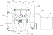
Fig. 1 is a schematic structural diagram of an embodiment of the present invention;
fig. 2 is a front view of an embodiment of the present invention;
fig. 3 is a top view of the embodiment of the present invention in fig. 2;
fig. 4 is a sectional view taken along line a-a of fig. 3 according to an embodiment of the present invention;
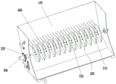
FIG. 5 is a schematic view of an embodiment of a filter assembly of the present invention;
fig. 6 is a schematic view of the installation of the filter disc according to the embodiment of the present invention;
fig. 7 is a schematic structural view of a filter disc according to an embodiment of the present invention;
fig. 8 is an exploded view of a filter tray according to an embodiment of the present invention;
fig. 9 is a front view of a filter tray according to an embodiment of the present invention;
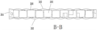
fig. 10 is a sectional view taken along line B-B of fig. 9 according to an embodiment of the present invention;
fig. 11 is a left side view of the embodiment of the present invention in fig. 9;
in the figure: 100-a water tank; 110-a roller; 200-a filter assembly; 210-a filter tray; 211-filtration shell plate; 212-a filter layer; 213-water passing tank; 214-a water outlet channel; 215-wave groove; 216-a connecting seat; 217-fastening bolts; 218-a fastening nut; 219-a limiting hole; 220-a limiting column; 230-connecting pipe; 300-a rotary joint; 310-water outlet pipe; 320-water pump; 330-a water collecting bucket; 340-a leakage prevention box; 350-a water collecting pipe; 360-outer shell; 370-a hollow shaft; 400-a power mechanism; 410-a motor; 420-a reducer; 500-a transmission mechanism; 510-a first sprocket; 520-a second sprocket; 530-a drive chain; 600-a cleaning mechanism; 700-controller.
Detailed Description
As shown in fig. 1 to 11, a sewage filter includes a water tank 100, a plurality of sets of filter assemblies 200 are disposed in the water tank 100, each filter assembly 200 includes a plurality of filter discs 210 having outer surfaces permeable to water and capable of filtering dirt, a connecting pipe 230 is disposed at the center of each filter disc 210 and communicated with the inside of the filter disc 210, and two ends of the connecting pipe 230 are rotatably connected to the water tank 100. The water tank 100 is used for storing sewage to be filtered, the filtering assemblies 200 are installed in the water tank 100, each group of filtering assemblies 200 comprises a connecting pipe 230 and a plurality of filtering discs 210, each filtering disc 210 can filter the sewage, and then a large filtering area can be formed by arranging the filtering discs in a limited space. The sewage is filtered by the end surface of the filter disc 210, enters the filter disc 210 and then flows into the connecting pipe 230.
In this embodiment, a rotary joint 300 is disposed at one end of the connection pipe 230, the end of the connection pipe 230 is connected to the hollow shaft of the rotary joint 300, a power mechanism 400 and a transmission mechanism 500 for driving the connection pipe 230 to rotate are disposed outside the water tank 100, and a cleaning mechanism 600 for cleaning dirt on the surface of the filter disc 210 is disposed inside the water tank 100. Preferably, rotary joint 300 adopts HD type rotary joint 300, HD type rotary joint 300 includes the shell body and can be relative shell body pivoted hollow shaft, the shell body of rotary joint is fixed motionless, the hollow shaft meets with connecting pipe 230, power unit 400 and drive mechanism 500 can drive connecting pipe 230 and hollow shaft and rotate, drive filter disc 210 and rotate, filter disc 210 rotates and can make filter disc 210's surface and cleaning mechanism 600 produce the friction, cleaning mechanism 600 can scrape off the dirt layer on filter disc 210 surface, avoid the dirt layer to block filter disc 210 surface, influence the filter effect.
In this embodiment, a water outlet pipe 310 is disposed at a water outlet of the rotary joint 300, a water pump 320 is disposed at a water outlet end of the water outlet pipe 310, a water collecting bucket 330 is disposed at a water outlet end of the water pump 320, a water collecting pipe 350 is disposed between the water pump 320 and the water collecting bucket 330, and a leakage preventing tank 340 is disposed below the rotary joint 300. The water outlet is arranged on the outer shell of the rotary joint 300, and the leakage-proof box 340 arranged at the lower end of the rotary joint 300 is beneficial to collecting leaked water drops in time when water leaks from the connecting part of the rotary joint 300 and the water outlet pipe 310.
In this embodiment, the bottom of the water tank 100 is further provided with a roller 110, and the outer wall of the water tank 100 is further provided with a control box electrically connected to the power mechanism 400 and the water pump 320. The control box can control the start and stop of the power mechanism 400 and the suction pump 320, and the roller 110 facilitates the movement of the water tank 100.
In this embodiment, the power mechanism 400 is a motor 410, a speed reducer 420 is disposed on an output shaft of the motor 410, the motor 410 and the speed reducer 420 are both fixedly mounted on an outer wall of the leakage preventing box 340, the transmission mechanism 500 includes a first sprocket 510 mounted on the output shaft of the speed reducer 420 and a second sprocket 520 mounted on a hollow shaft of the rotary joint 300, and a transmission chain 530 is disposed between the first sprocket 510 and the second sprocket 520. The rotation of motor 410 can drive first sprocket 510 and rotate, and first sprocket 510 rotates and passes through the transmission chain 530 transmission, can drive second sprocket 520 and rotate, and second sprocket 520 rotates the hollow shaft that can drive rotary joint 300 and rotates, and the hollow shaft rotates, can drive the connecting pipe 230 with hollow shaft connection and rotate, and then drive filter disc 210 and rotate.
In this embodiment, the filter disc 210 includes two spliced filter shell plates 211, a filter layer 212 attached to an end surface of the filter shell plate is disposed on an outer periphery of the filter shell plate, a water passing groove 213 is disposed on the filter shell plate, a water outlet channel 214 communicated with the water passing groove 213 is disposed in a center of the filter shell plate, a wave groove 215 is disposed on an end surface of the filter layer 212 away from the filter shell plate, a connecting seat 216 is disposed on the filter shell plate 211, a fastening bolt 217 for fixing the two filter shell plates 211 is disposed on the connecting seat 216, a fastening nut 218 is sleeved on the fastening bolt 217, and a limit hole 219 and a limit column 220 are disposed on a diameter end surface of the filter shell plate 211; the filtering shell plate is a plastic plate, the filtering layer 212 is a filtering paperboard, and the water outlet channel 214 is communicated with the connecting pipe 230. The filter layers 212 are arranged on the two sides of the semicircular shell plate, so that the contact area of the outer surface of the filter disc 210 and sewage can be filtered, and the filter area is increased; the wave groove 215 can lead the dirt layer to crack under the action of water pressure or air pressure, thereby promoting the dirt layer to fall off and preventing the filtering layer 212 from being blocked; when the filter shell plates 211 are installed, the limiting holes 219 of the two filter shell plates 211 are matched with the limiting posts 220, so that the limiting posts 220 of the two filter shell plates 211 are inserted into the limiting holes 219, the fastening bolts 217 penetrate through the connecting seat 216, and the two filter shell plates 211 are fixed by the fastening nuts 218 for locking and fixing.
In this embodiment, the iron wire of the cleaning mechanism 600 is transversely fixed on the inner wall of the water tank 100. The wire can scrape off dirt on the surface of the filter disc 210 when the filter disc 210 rotates.
The specific implementation process comprises the following steps: the sewage is led into the water tank 100, the power mechanism 400 and the water pump 320 are controlled to be started through the controller 700, when the water pump 320 is started, negative pressure is formed in the connecting pipe 230 and the filter disc 210, water flow in the water tank 100 flows into the filter disc 210 through the end face of the filter disc 210, when the water flow passes through the end face of the filter disc 210, dirt contained in the water flow is filtered outside the filter disc 210, and then the filtered water sequentially passes through the connecting pipe 230, the rotary joint 300, the water outlet pipe 310, the water pump 320 and the water collecting pipe 350 and finally flows into the water collecting barrel 330 for storage; in the filtering process, the dirt is accumulated on the surface of the filter disc 210, the power mechanism 400 rotates and is driven by the transmission mechanism 500 to drive the connecting pipe 230 and the filter disc 210 to rotate, and in the rotating process of the filter disc 210, the surface of the filter disc 210 can rub against the cleaning mechanism 600 to clean the dirt on the surface of the filter disc 210, and the cleaned dirt falls into the bottom of the water tank 100 under the action of gravity after being scraped.
Above-mentioned operation flow and software and hardware configuration only do as the preferred embodiment of the utility model discloses a not therefore restrict the patent scope of the utility model, all utilize the utility model discloses the equivalent transform of doing of description and attached drawing content, or directly or indirectly use in relevant technical field, all the same reason is included in the patent protection scope of the utility model.
Claims (7)
1. The utility model provides a sewage filter, includes the water tank, its characterized in that: be provided with a plurality of filter assembly in the water tank, filter assembly includes that a plurality of surface can permeate water and filter the filter disc of dirt, wears to be equipped with at the center of filter disc with the inside connecting pipe that communicates of filter disc, rotates between connecting pipe both ends and the water tank and is connected.
2. The sewage filter of claim 1, wherein: the rotary joint is arranged at one end of the connecting pipe, the end part of the connecting pipe is connected with the hollow shaft of the rotary joint, a power mechanism and a transmission mechanism which are used for driving the connecting pipe to rotate are arranged outside the water tank, and a cleaning mechanism which is used for cleaning dirt on the surface of the filter disc is arranged in the water tank.
3. The sewage filter of claim 2, wherein: a water outlet pipe is arranged at a water outlet of the rotary joint, a water suction pump is arranged at the water outlet end of the water outlet pipe, a water collecting barrel is arranged at the water outlet end of the water suction pump, a water collecting pipe is arranged between the water suction pump and the water collecting barrel, and a leakage-proof tank is arranged below the rotary joint.
4. The sewage filter of claim 3, wherein: the bottom of the water tank is also provided with a roller, and the outer wall of the water tank is also provided with a control box which is electrically connected with the power mechanism and the water suction pump.
5. The sewage filter of claim 2, wherein: the power mechanism is a motor, a speed reducer is arranged on an output shaft of the motor, the motor and the speed reducer are both fixedly installed on the outer wall of the leakage-proof box, the transmission mechanism comprises a first chain wheel installed on the output shaft of the speed reducer and a second chain wheel installed on the hollow shaft of the rotary joint, and a transmission chain is arranged between the first chain wheel and the second chain wheel.
6. The sewage filter of claim 1, wherein: the filter disc comprises two spliced filter shell plates, a filter layer attached to the end face of each filter shell plate is arranged on the periphery of each filter shell plate, a water passing groove is formed in each filter shell plate, a water outlet channel communicated with the water passing groove is formed in the center of each filter shell plate, a wave groove is formed in the end face, away from the filter shell plates, of each filter layer, a connecting seat is arranged on each filter shell plate, fastening bolts used for fixing the two filter shell plates are arranged on the connecting seats, fastening nuts are sleeved on the fastening bolts, and limiting holes and limiting columns are formed in the diameter end faces of the filter shell plates; the filtering shell plate is a plastic plate, the filtering layer is a filtering paper plate, and the water outlet channel is communicated with the connecting pipe.
7. The sewage filter of claim 2, wherein: the iron wire of clean mechanism, the iron wire is transversely fixed at the water tank inner wall.
Priority Applications (1)
| Application Number | Priority Date | Filing Date | Title |
|---|---|---|---|
| CN201921367122.9U CN210583931U (en) | 2019-08-22 | 2019-08-22 | Sewage filter |
Applications Claiming Priority (1)
| Application Number | Priority Date | Filing Date | Title |
|---|---|---|---|
| CN201921367122.9U CN210583931U (en) | 2019-08-22 | 2019-08-22 | Sewage filter |
Publications (1)
| Publication Number | Publication Date |
|---|---|
| CN210583931U true CN210583931U (en) | 2020-05-22 |
Family
ID=70701732
Family Applications (1)
| Application Number | Title | Priority Date | Filing Date |
|---|---|---|---|
| CN201921367122.9U Expired - Fee Related CN210583931U (en) | 2019-08-22 | 2019-08-22 | Sewage filter |
Country Status (1)
| Country | Link |
|---|---|
| CN (1) | CN210583931U (en) |
Cited By (1)
| Publication number | Priority date | Publication date | Assignee | Title |
|---|---|---|---|---|
| CN110339611A (en) * | 2019-08-22 | 2019-10-18 | 泉州铂克新材料科技有限公司 | Effluent filter and its working method |
-
2019
- 2019-08-22 CN CN201921367122.9U patent/CN210583931U/en not_active Expired - Fee Related
Cited By (1)
| Publication number | Priority date | Publication date | Assignee | Title |
|---|---|---|---|---|
| CN110339611A (en) * | 2019-08-22 | 2019-10-18 | 泉州铂克新材料科技有限公司 | Effluent filter and its working method |
Similar Documents
| Publication | Publication Date | Title |
|---|---|---|
| CN116282774B (en) | Industrial circulating cooling water filtering device and filtering method thereof | |
| CN207288151U (en) | A kind of auto parts Quick cleaning device | |
| CN208018239U (en) | A kind of filter device for sewage disposal | |
| CN210583931U (en) | Sewage filter | |
| CN205084500U (en) | Water wheels formula loop filter machine | |
| CN206604241U (en) | A kind of novel pressure formula mechanical filter | |
| CN116102116A (en) | Sewage treatment's active carbon adsorption equipment | |
| CN201101951Y (en) | High-efficiency oil-water and liquid-solid separating equipment | |
| CN110589942A (en) | Flocculation and precipitation device for sewage treatment | |
| CN210097137U (en) | Foaming polypropylene is sewage filter equipment for white particle | |
| CN217773511U (en) | Filter cartridge cleaning device | |
| CN213221149U (en) | A filter equipment for carclazyte in grease | |
| CN207143075U (en) | A kind of dual sludge dewatering environmental protection equipment | |
| CN113087186B (en) | Household drinking water defluorination system and defluorination method | |
| CN213527701U (en) | Fiber rotary disc filtering tank for sewage treatment | |
| JP5904874B2 (en) | Filtration device | |
| CN209237514U (en) | A kind of sewage precipitation device | |
| CN212188136U (en) | Dirt separating equipment for environmental pollution remediation | |
| CN107235522A (en) | A kind of industrial waste water disposal device | |
| CN209848462U (en) | Precision filter with easily replaced filter element | |
| CN207877419U (en) | A kind of efficient sewage treatment installation | |
| CN207361813U (en) | A kind of efficiently water purification quartz filter | |
| CN207361812U (en) | A kind of efficiently water purification quartz filter | |
| CN206924473U (en) | A kind of industrial sewage processing unit of high-efficiency environment friendly | |
| CN206809861U (en) | A kind of rotary wings microporous filter |
Legal Events
| Date | Code | Title | Description |
|---|---|---|---|
| GR01 | Patent grant | ||
| GR01 | Patent grant | ||
| CF01 | Termination of patent right due to non-payment of annual fee |
Granted publication date: 20200522 Termination date: 20210822 |
|
| CF01 | Termination of patent right due to non-payment of annual fee |