CN210573165U - Portable DLP technique projecting apparatus - Google Patents
Portable DLP technique projecting apparatus Download PDFInfo
- Publication number
- CN210573165U CN210573165U CN201921768996.5U CN201921768996U CN210573165U CN 210573165 U CN210573165 U CN 210573165U CN 201921768996 U CN201921768996 U CN 201921768996U CN 210573165 U CN210573165 U CN 210573165U
- Authority
- CN
- China
- Prior art keywords
- equipment main
- main part
- carriage
- portable
- equipment principal
- Prior art date
- Legal status (The legal status is an assumption and is not a legal conclusion. Google has not performed a legal analysis and makes no representation as to the accuracy of the status listed.)
- Active
Links
Images


Landscapes
- Projection Apparatus (AREA)
Abstract
The utility model discloses a portable DLP technique projecting apparatus, including the equipment principal, fixed mounting has the projection head that is used for projecting in the equipment principal, and the front end of equipment principal is provided with the mouth of raising one's voice, the upper end intermediate position department of equipment principal is provided with portable frame, and the louvre that is used for the heat dissipation cooling is all offered to the both sides of equipment principal, the rear end of equipment principal is provided with power source, and the rear end of equipment principal is equipped with the USB interface, the lower surface of equipment principal is provided with removable landing leg. A portable DLP technique projecting apparatus, through the portable frame that sets up, make things convenient for the transportation of relevant personnel to carry the projecting apparatus, simplify and carry work, improve and carry the simplicity and convenience, adopt removable landing leg, the cooperation is using the expansion bracket, can dismantle the landing leg as required, can also adjust the length of landing leg simultaneously, guarantee that the projecting apparatus is stable places on the platform.
Description
Technical Field
The utility model relates to a projecting apparatus field, in particular to portable DLP technique projecting apparatus.
Background
A projector, also called a projector, is a device that can project images or videos onto a curtain, and can be connected with a computer, a VCD, a DVD, a BD, a game machine, a DV, etc. through different interfaces to play corresponding video signals. Projectors are widely used in homes, offices, schools and entertainment places at present, and have different types such as CRT, LCD and DLP according to different working modes. In places with higher requirements, DLP technology projectors are often adopted; when using, the existing DLP technical projector is either installed on a support to be used or directly placed on a platform to be used, the structure is definite, the DLP technical projector is not convenient to carry, and supporting legs of the DLP technical projector are fixed on an equipment main body and cannot be detached and adjusted, so that certain limitation exists during use.
SUMMERY OF THE UTILITY MODEL
A primary object of the present invention is to provide a portable DLP technology projector, which can effectively solve the problems of the background art.
In order to achieve the above purpose, the utility model adopts the following technical scheme:
the utility model provides a portable DLP technique projecting apparatus, includes equipment principal, the last fixed mounting of equipment principal has the projection head that is used for the projection, and equipment principal's front end is provided with the mouth of raising one's voice, equipment principal's upper end intermediate position department is provided with portable frame, and equipment principal's both sides all offer the louvre that is used for the heat dissipation cooling, equipment principal's rear end is provided with power source, and equipment principal's rear end is equipped with the USB interface, equipment principal's lower surface is provided with removable landing leg.
Preferably, the portable frame is including accomodating groove, spout, first carriage, second carriage, slider and horizontal pole, accomodate the groove set up with the equipment main part on, and accomodate the inslot and be equipped with the spout, equal fixed mounting has the slider on first carriage and the second carriage, and the slider is located within the spout, be equipped with the horizontal pole on first carriage and the second carriage, and first carriage, second carriage all rotate with the horizontal pole and are connected.
Preferably, removable landing leg includes fixed block, draw-in groove, alignment jig, can tear piece, fixture block and slipmat open, the draw-in groove has been seted up on the fixed block, and the upper end fixed mounting of fixed block has the alignment jig, alignment jig and fixed block all set up in the recess on the equipment main part, the upper surface intermediate position department fixed mounting of the piece that can tear open has the fixture block, and the lower extreme of removable piece is provided with the slipmat.
Preferably, the adjusting frame comprises a fixing rod, a screw hole, an adjusting rod and a screw rod, the screw hole is formed in the fixing rod, the screw rod is fixedly mounted on the adjusting rod, the upper end of the screw rod is located in the screw hole, and the screw rod is in threaded connection with the screw hole.
Preferably, a CD card slot is arranged at a position, close to the power interface, of the rear end of the device main body, and a DHMI interface is arranged at a position, close to the USB interface, of the rear end of the device main body.
Preferably, a projection lens is arranged in the projection head, and a loudspeaker is arranged in the loudspeaker port.
Compared with the prior art, the utility model discloses following beneficial effect has: this portable DLP technique projecting apparatus through the portable frame that sets up, makes things convenient for the transportation of relevant personnel to carry the projecting apparatus, simplifies and carries work, improves and carries the simplicity, adopts removable landing leg, is coordinating the expansion bracket and is using, can dismantle the landing leg as required, can also adjust the length of landing leg simultaneously, guarantees that the projecting apparatus is stable places on the platform.
Drawings
Fig. 1 is a schematic view of an overall structure of a portable DLP projector according to the present invention;
fig. 2 is a schematic structural view of a portable DLP technology projector hand-held rack of the present invention;
fig. 3 is a schematic structural diagram of a power interface of a portable DLP technology projector according to the present invention;
fig. 4 is a schematic structural diagram of a detachable leg of a portable DLP technology projector according to the present invention;
fig. 5 is the utility model relates to a portable DLP technique projecting apparatus alignment jig's schematic structure.
In the figure: 1. an apparatus main body; 2. a projection head; 3. a sound raising port; 4. a portable frame; 401. a receiving groove; 402. a chute; 403. a first carriage; 404. a second carriage; 405. a slider; 406. a cross bar; 5. heat dissipation holes; 6. a power interface; 7. a USB interface; 8. a detachable leg; 801. a fixed block; 802. a card slot; 803. an adjusting bracket; 8031. fixing the rod; 8032. a screw hole; 8033. adjusting a rod; 8034. a screw; 804. a detachable block; 805. a clamping block; 806. a non-slip mat; 9. a CD card slot; 10. a DHMI interface.
Detailed Description
In order to make the technical means, creation features, achievement purposes and functions of the present invention easy to understand, the present invention is further described below with reference to the following embodiments.
In the description of the present invention, it should be noted that the terms "upper", "lower", "inner", "outer", "front end", "rear end", "both ends", "one end", "the other end" and the like indicate orientations or positional relationships based on the orientations or positional relationships shown in the drawings, and are only for convenience of description and simplification of description, but do not indicate or imply that the device or element to which the reference is made must have a specific orientation, be constructed in a specific orientation, and be operated, and thus, should not be construed as limiting the present invention. Furthermore, the terms "first" and "second" are used for descriptive purposes only and are not to be construed as indicating or implying relative importance.
In the description of the present invention, it is to be noted that, unless otherwise explicitly specified or limited, the terms "mounted," "disposed," "connected," and the like are to be construed broadly, and for example, "connected" may be either fixedly connected or detachably connected, or integrally connected; can be mechanically or electrically connected; they may be connected directly or indirectly through intervening media, or they may be interconnected between two elements. The specific meaning of the above terms in the present invention can be understood in specific cases to those skilled in the art.
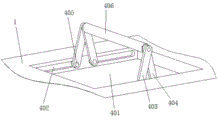
As shown in fig. 1-5, a portable DLP technology projector includes an apparatus main body 1, a projection head 2 for projection is fixedly mounted on the apparatus main body 1, a sound-raising port 3 is provided at the front end of the apparatus main body 1, a hand-held rack 4 is provided at the middle position of the upper end of the apparatus main body 1, heat-dissipating holes 5 for heat dissipation and temperature reduction are provided at both sides of the apparatus main body 1, a power supply interface 6 is provided at the rear end of the apparatus main body 1, a USB interface 7 is provided at the rear end of the apparatus main body 1, and detachable support legs 8 are provided at the lower surface of the apparatus main body 1;
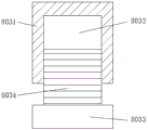
the portable rack 4 comprises a storage groove 401, a sliding groove 402, a first sliding frame 403, a second sliding frame 404, a sliding block 405 and a cross bar 406, the storage groove 401 is formed on the equipment main body 1, the sliding groove 402 is arranged in the storage groove 401, the sliding block 405 is fixedly arranged on each of the first sliding frame 403 and the second sliding frame 404, the sliding block 405 is positioned in the sliding groove 402, the cross bar 406 is arranged on each of the first sliding frame 403 and the second sliding frame 404, and the first sliding frame 403 and the second sliding frame 404 are rotatably connected with the cross bar 406; the detachable supporting leg 8 comprises a fixing block 801, a clamping groove 802, an adjusting frame 803, a detachable block 804, a clamping block 805 and an anti-skid pad 806, the clamping groove 802 is formed in the fixing block 801, the adjusting frame 803 is fixedly installed at the upper end of the fixing block 801, the adjusting frame 803 and the fixing block 801 are both arranged in a groove in the device main body 1, the clamping block 805 is fixedly installed at the middle position of the upper surface of the detachable block 804, and the anti-skid pad 806 is arranged at the lower end of the detachable block 804; the adjusting frame 803 comprises a fixing rod 8031, a screw hole 8032, an adjusting rod 8033 and a screw rod 8034, the fixing rod 8031 is provided with the screw hole 8032, the adjusting rod 8033 is fixedly provided with the screw rod 8034, the upper end of the screw rod 8034 is positioned in the screw hole 8032, and the screw rod 8034 is in threaded connection with the screw hole 8032; a CD card slot 9 is arranged at the position, close to the power interface 6, of the rear end of the equipment main body 1, and a DHMI interface 10 is arranged at the position, close to the USB interface 7, of the rear end of the equipment main body 1; a projection lens is arranged in the projection head 2, and a loudspeaker is arranged in the loudspeaker opening 3.
It should be noted that, the utility model relates to a portable DLP technique projector, when using, the staff places equipment main part 1 on suitable platform, support it through removable landing leg 8, utilize the length of each landing leg of alignment jig 803 in the removable landing leg 8 to adjust, guarantee stable the placing of equipment main part 1, when adjusting, rotate removable piece 804, removable piece 804 takes fixed block 801 to rotate, thereby it is rotatory to take regulation pole 8033 and screw rod 8034, screw rod 8034 goes up and down in screw 8032 when rotating, and then change the length of whole alignment jig 803, accomplish the regulation work of team's landing leg length, when all removable landing legs 8 all adjust and accomplish the back, the staff is connected to power source 6 with the one end of power cord, the other end is connected to the power, make equipment main part 1 circular telegram can use, utilize the data line afterwards, cooperation USB interface 7, The DHMI interface 10 connects the equipment body 1 to a computer, after the connection is completed, the equipment is started to be used, when the equipment is used, information such as videos and the like at the projection position of the screen on the projection head 2 of the equipment body 1 is projected on the screen, relevant personnel can watch the information through the projection on the screen, meanwhile, sound is broadcast from the loudspeaker port 3, listening of the relevant personnel is facilitated, when the equipment body 1 is used, internal elements can generate heat, the heat is dissipated through the heat dissipation holes 5 at two sides of the equipment body 1, the temperature of the equipment body 1 is ensured not to be too high, normal use of the equipment body 1 is ensured, if the equipment does not need to be supported during use, a worker draws out the fixture block 805 in the fixture groove 802 to disassemble the detachable block 804 and the anti-skid pad 806, after the use of the projector is completed, the worker pulls out a connecting wire, lifts the cross rod 406, and the cross rod 406 generates upward force to the first sliding frame 403 and, the first sliding frame 403 and the second sliding frame 404 are forced to slide in the sliding groove 402 through the sliding block 405 until the sliding block 405 is located at the end of the sliding groove 402, then the cross rod 406 is held by hands, the equipment is lifted through the whole lifting frame 4, then the equipment is moved and transported, after the equipment is transported to a storage place, the cross rod 406 is loosened, the first sliding frame 403 and the second sliding frame 404 move into the storage groove 401 under the action of gravity, and the equipment is transported through the lifting frame 4 when in use.
The basic principles and the main features of the invention and the advantages of the invention have been shown and described above. It will be understood by those skilled in the art that the present invention is not limited to the above embodiments, and that the foregoing embodiments and descriptions are provided only to illustrate the principles of the present invention without departing from the spirit and scope of the present invention. The scope of the invention is defined by the appended claims and equivalents thereof.
Claims (6)
1. The utility model provides a portable DLP technique projecting apparatus which characterized in that: including equipment main part (1), fixed mounting has projection head (2) that are used for the projection on equipment main part (1), and the front end of equipment main part (1) is provided with lou mouth (3), the upper end intermediate position department of equipment main part (1) is provided with portable frame (4), and the louvre (5) that are used for the heat dissipation cooling are all offered to the both sides of equipment main part (1), the rear end of equipment main part (1) is provided with power source (6), and the rear end of equipment main part (1) is equipped with USB interface (7), the lower surface of equipment main part (1) is provided with removable landing leg (8).
2. A portable DLP technology projector as claimed in claim 1, wherein: hand-held rack (4) including accomodating groove (401), spout (402), first carriage (403), second carriage (404), slider (405) and horizontal pole (406), accomodate on groove (401) set up with equipment main part (1), and be equipped with spout (402) in accomodating groove (401), equal fixed mounting has slider (405) on first carriage (403) and second carriage (404), and slider (405) is located within spout (402), be equipped with horizontal pole (406) on first carriage (403) and second carriage (404), and first carriage (403), second carriage (404) all rotate with horizontal pole (406) and be connected.
3. A portable DLP technology projector as claimed in claim 1, wherein: removable landing leg (8) are including fixed block (801), draw-in groove (802), adjusting bracket (803), removable piece (804), fixture block (805) and slipmat (806), draw-in groove (802) have been seted up on fixed block (801), and the upper end fixed mounting of fixed block (801) has adjusting bracket (803), adjusting bracket (803) and fixed block (801) all set up in the recess on equipment main part (1), the upper surface intermediate position department fixed mounting of removable piece (804) has fixture block (805), and the lower extreme of removable piece (804) is provided with slipmat (806).
4. A portable DLP technology projector as claimed in claim 3, wherein: the adjusting frame (803) comprises a fixing rod (8031), a screw hole (8032), an adjusting rod (8033) and a screw rod (8034), the screw hole (8032) is formed in the fixing rod (8031), the screw rod (8034) is fixedly installed on the adjusting rod (8033), the upper end of the screw rod (8034) is located in the screw hole (8032), and the screw rod (8034) is in threaded connection with the screw hole (8032).
5. A portable DLP technology projector as claimed in claim 1, wherein: the rear end of the equipment main body (1) is provided with a CD card slot (9) at a position close to the power interface (6), and the rear end of the equipment main body (1) is provided with a DHMI interface (10) at a position close to the USB interface (7).
6. A portable DLP technology projector as claimed in claim 1, wherein: the projection head (2) is internally provided with a projection lens, and the sound raising port (3) is internally provided with a loudspeaker.
Priority Applications (1)
| Application Number | Priority Date | Filing Date | Title |
|---|---|---|---|
| CN201921768996.5U CN210573165U (en) | 2019-10-21 | 2019-10-21 | Portable DLP technique projecting apparatus |
Applications Claiming Priority (1)
| Application Number | Priority Date | Filing Date | Title |
|---|---|---|---|
| CN201921768996.5U CN210573165U (en) | 2019-10-21 | 2019-10-21 | Portable DLP technique projecting apparatus |
Publications (1)
| Publication Number | Publication Date |
|---|---|
| CN210573165U true CN210573165U (en) | 2020-05-19 |
Family
ID=70661805
Family Applications (1)
| Application Number | Title | Priority Date | Filing Date |
|---|---|---|---|
| CN201921768996.5U Active CN210573165U (en) | 2019-10-21 | 2019-10-21 | Portable DLP technique projecting apparatus |
Country Status (1)
| Country | Link |
|---|---|
| CN (1) | CN210573165U (en) |
-
2019
- 2019-10-21 CN CN201921768996.5U patent/CN210573165U/en active Active
Similar Documents
| Publication | Publication Date | Title |
|---|---|---|
| CN210222069U (en) | Integrated intelligent test terminal | |
| CN210573165U (en) | Portable DLP technique projecting apparatus | |
| CN208431530U (en) | A kind of projector installation and adjustment frame | |
| CN113380078A (en) | Projection equipment convenient for storage and placement for computer major teaching | |
| CN112944170A (en) | Projection arrangement that wisdom teaching was used | |
| CN210574369U (en) | Angle control's tall and erect projecting apparatus of ann is used in teaching | |
| CN210440935U (en) | Projecting apparatus hanging box | |
| WO2023124662A1 (en) | Movie and television planning work display projector | |
| CN212208589U (en) | Projecting apparatus is used in teaching | |
| CN113048366B (en) | Multimedia classroom projecting apparatus installation hangs mount | |
| CN211905956U (en) | Portable projector for geography teaching | |
| CN219282831U (en) | Projection equipment convenient to operation uses | |
| CN209823951U (en) | Sound-making noise-proof device for later stage of film and television | |
| CN211014995U (en) | Animation projection equipment | |
| CN212456195U (en) | Projector mounting bracket | |
| CN220359646U (en) | Distributed digital video controller | |
| CN214405320U (en) | Animation broadcast projecting apparatus | |
| CN219734798U (en) | Multi-screen interactive operation table device for display | |
| CN211791824U (en) | Projection video recording all-in-one machine for meeting room | |
| CN213582611U (en) | Projector bracket for education and teaching | |
| CN214541088U (en) | Medical image teaching device | |
| CN216411846U (en) | Processing equipment for projector edge fusion | |
| CN210924166U (en) | Digital media projector convenient to installation | |
| CN210804173U (en) | Image processing device with telescopic mechanism based on computer | |
| CN216210444U (en) | Multifunctional computer projection display device |
Legal Events
| Date | Code | Title | Description |
|---|---|---|---|
| GR01 | Patent grant | ||
| GR01 | Patent grant |