CN210568122U - Flame lamp and lamp - Google Patents
Flame lamp and lamp Download PDFInfo
- Publication number
- CN210568122U CN210568122U CN201920753716.7U CN201920753716U CN210568122U CN 210568122 U CN210568122 U CN 210568122U CN 201920753716 U CN201920753716 U CN 201920753716U CN 210568122 U CN210568122 U CN 210568122U
- Authority
- CN
- China
- Prior art keywords
- lamp
- light guide
- flame
- light
- panel
- Prior art date
- Legal status (The legal status is an assumption and is not a legal conclusion. Google has not performed a legal analysis and makes no representation as to the accuracy of the status listed.)
- Active
Links
Images


Classifications
-
- F—MECHANICAL ENGINEERING; LIGHTING; HEATING; WEAPONS; BLASTING
- F21—LIGHTING
- F21S—NON-PORTABLE LIGHTING DEVICES; SYSTEMS THEREOF; VEHICLE LIGHTING DEVICES SPECIALLY ADAPTED FOR VEHICLE EXTERIORS
- F21S10/00—Lighting devices or systems producing a varying lighting effect
- F21S10/04—Lighting devices or systems producing a varying lighting effect simulating flames
- F21S10/043—Lighting devices or systems producing a varying lighting effect simulating flames by selectively switching fixed light sources
-
- F—MECHANICAL ENGINEERING; LIGHTING; HEATING; WEAPONS; BLASTING
- F21—LIGHTING
- F21V—FUNCTIONAL FEATURES OR DETAILS OF LIGHTING DEVICES OR SYSTEMS THEREOF; STRUCTURAL COMBINATIONS OF LIGHTING DEVICES WITH OTHER ARTICLES, NOT OTHERWISE PROVIDED FOR
- F21V23/00—Arrangement of electric circuit elements in or on lighting devices
- F21V23/003—Arrangement of electric circuit elements in or on lighting devices the elements being electronics drivers or controllers for operating the light source, e.g. for a LED array
-
- F—MECHANICAL ENGINEERING; LIGHTING; HEATING; WEAPONS; BLASTING
- F21—LIGHTING
- F21V—FUNCTIONAL FEATURES OR DETAILS OF LIGHTING DEVICES OR SYSTEMS THEREOF; STRUCTURAL COMBINATIONS OF LIGHTING DEVICES WITH OTHER ARTICLES, NOT OTHERWISE PROVIDED FOR
- F21V5/00—Refractors for light sources
- F21V5/04—Refractors for light sources of lens shape
- F21V5/043—Refractors for light sources of lens shape the lens having cylindrical faces, e.g. rod lenses, toric lenses
-
- F—MECHANICAL ENGINEERING; LIGHTING; HEATING; WEAPONS; BLASTING
- F21—LIGHTING
- F21V—FUNCTIONAL FEATURES OR DETAILS OF LIGHTING DEVICES OR SYSTEMS THEREOF; STRUCTURAL COMBINATIONS OF LIGHTING DEVICES WITH OTHER ARTICLES, NOT OTHERWISE PROVIDED FOR
- F21V2200/00—Use of light guides, e.g. fibre optic devices, in lighting devices or systems
-
- F—MECHANICAL ENGINEERING; LIGHTING; HEATING; WEAPONS; BLASTING
- F21—LIGHTING
- F21Y—INDEXING SCHEME ASSOCIATED WITH SUBCLASSES F21K, F21L, F21S and F21V, RELATING TO THE FORM OR THE KIND OF THE LIGHT SOURCES OR OF THE COLOUR OF THE LIGHT EMITTED
- F21Y2115/00—Light-generating elements of semiconductor light sources
- F21Y2115/10—Light-emitting diodes [LED]
Abstract
The utility model relates to a flame lamp, which comprises a lamp holder, a control panel, a LED lamp panel, a light guide device, a lens and a face shell from bottom to top in sequence; the control panel is arranged on the lamp holder, the lamp holder is electrically connected with the LED lamp panel, the LED lamp panel is provided with a plurality of LED lamp beads, and the control panel can control the LED lamp beads on the LED lamp panel to form irregular jump from bright to dark; the light guide device is sleeved inside the lens, and the face shell is sleeved above the light guide device. The utility model also discloses a lamps and lanterns, the foreland of adoption flame lamp. The utility model discloses a flame lamp is through optimizing leaded light device and lens structure for the dynamic reality of flame effect that produces, light atmosphere is effectual, and the cost is lower moreover, realizes easily. The utility model discloses a flame lamp can also be applied to multiple lamps and lanterns through adding the accessory.
Description
Technical Field
The utility model relates to the technical field of lighting technology, especially, relate to a flame lamp and lamps and lanterns.
Background
Along with the development of society and the improvement of living standard of people, the living taste and the appreciation level of people are also continuously improved. The lamp is used as a part involved in life of people, particularly at night of a city, the requirement of people on the lamp is not limited to illumination, but the lamp is used as a decorative lamp, so that more aesthetic feeling, atmosphere and interest are added to a living space.
The flame lamp is used as a light-emitting device for simulating the flame effect, and has no harm to the environment and human bodies due to chemical components generated by actual combustible substances, and no fire hazard, so that the flame lamp can be widely applied to places such as large-scale banquets, streets, fashionable homes and the like, the environment atmosphere is greatly improved, and the flame lamp is deeply loved by people.
In the prior art, the flame generation mode of a flame lamp is mainly realized by two schemes:
one, concrete scheme is through adopting cylindrical or toper lamp plate, and the change of reunion light realizes the flame effect, and this scheme is most common, and this kind of scheme is higher to the requirement of lamp plate, in order to satisfy the molding requirement, and a lot of adoption flexible lamp plates have undoubtedly improved the cost, are unfavorable for promoting.
The second scheme is that a flat lamp panel is adopted, the flame effect is mainly realized by regulating and controlling the light and shade change of the light of the circuit board, and the scheme has higher requirements on IC design and is difficult to realize.
SUMMERY OF THE UTILITY MODEL
In order to solve the prior technical problem, the utility model provides a flame lamp and lamps and lanterns.
The specific contents of the utility model are as follows: a flame lamp comprises a lamp holder, a control panel, an LED lamp panel, a light guide device, a lens and a face shell from bottom to top in sequence; the control panel is arranged on the lamp holder, the lamp holder is electrically connected with the LED lamp panel, the LED lamp panel is provided with a plurality of LED lamp beads, and the control panel can control the LED lamp beads on the LED lamp panel to form irregular jump from bright to dark; the light guide device is sleeved inside the lens, and the face shell is sleeved above the light guide device. The control panel can control a plurality of LED lamp pearls on the LED lamp plate form by bright to dark anomalous transformation, form the effect that the light is beated, then the light guide device goes up the light on the LED lamp plate from bottom to top, reaches the effect of flame.
Further, the light guide device comprises a light guide column, a lens is sleeved outside the light guide column, and the light guide column is step-shaped and the diameter of each step is reduced from bottom to top in sequence.
Further, the light guide column is formed by surrounding a plurality of single light guide columns, and the heights of the light guide columns are sequentially reduced from inside to outside.
Further, the light guide device comprises a plurality of layers of light emitting surfaces, lenses are arranged outside the plurality of layers of light emitting surfaces, each layer of light emitting surface is provided with an LED lamp panel, the area of each layer of light emitting surface is sequentially reduced from bottom to top, a light guide plate is arranged in each lens, and the inner surface of each light guide plate is in a continuous concave-convex shape.
Further, the multiple layers of light-emitting surfaces sequentially comprise a first light-emitting surface and an nth light-emitting surface … from bottom to top, and the light-emitting surfaces of the layers are connected through the upright posts; the periphery of the first light emitting surface is adapted to the bottom of the light guide plate, the cross-sectional area of the light guide plate is reduced from bottom to top, and the light guide plate comprises a plurality of straight surfaces or inclined surfaces.
Further, leaded light device includes the diffusion barrier, the outside of diffusion barrier is equipped with transparent shell, and the bottom setting of diffusion barrier is on the base, and the top contacts with transparent shell's top is inside, and transparent shell top and face-piece bottom joint each other are equipped with the threading pipe between control panel and face-piece.
Furthermore, the diffusion film is a microstructure diffusion film with an angle, and the rolled shape of the diffusion film comprises one of a cylinder, a trilateral, a quadrilateral, a pentagon, a hexagon, a heptagon and an octagon, wherein m is more than or equal to 3; the shape of the transparent shell is matched with that of the diffusion film; the transparent shell is also provided with an outer cover which is of a hollow structure, and the hollow patterns comprise one or more of rhombus, round, oblique strip and straight strip.
Further, the diffusion membrane is fixed inside the transparent shell through glue or glue paste, or a transparent inner cover is arranged on the inner side of the diffusion membrane, the shape of the transparent inner cover is matched with that of the transparent shell, and the diffusion membrane is arranged between the transparent inner cover and the transparent shell.
Further, still include the handle, the handle sets up on the face-piece. Can conveniently move, and can also be hung through lifting rope/lifting hook simultaneously, be convenient for settle.
Further, the lamp holder further comprises a USB connecting device and an electric storage unit which are arranged in the lamp holder.
Further, still include solar panel, solar panel sets up in the face-piece top.
The utility model also discloses a lamp, include as above the flame lamp, still include base and mounting, the base links to each other with the mounting with the lamp stand fixed connection of flame lamp.
Further, the mounting is the wall lamp fixing base, and the wall lamp fixing base is fixed on the wall, and the wall lamp fixing base is equipped with the fixed head that is connected with the base.
Further, the mounting includes siphunculus, siphunculus connecting piece and the ground round pin of inserting that from the top down connects gradually, the siphunculus links to each other with the base.
The utility model has the advantages that: the utility model discloses a flame lamp is through optimizing leaded light device and lens structure for the dynamic reality of flame effect that produces, light atmosphere is effectual, and the cost is lower moreover, realizes easily. The utility model discloses a flame lamp can also be applied to multiple lamps and lanterns through adding the accessory.
Drawings
The following further explains the embodiments of the present invention with reference to the drawings.
Fig. 1 is an exploded view of embodiment 1 of the present invention;
fig. 2 is a schematic view showing a lens structure of a flame lamp according to embodiment 1 of the present invention, in which fig. 2(a) is a sectional view of a lens, fig. 2(b) is an enlarged view of a region a of fig. 2(a), the notch shape in fig. 2(b) -1 is a circular arc, the notch shape in fig. 2(b) -2 is a triangle, the notch shape in fig. 2(b) -3 is an L-shape, the notch shape in fig. 2(b) -4 is a trapezoid, and the notch shape in fig. 2(b) -5 is a polygonal triangle;
FIG. 3 is an overall schematic view of embodiment 1;
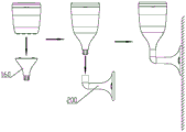
FIG. 4 is a state diagram of use of embodiment 1;
FIG. 5 is a schematic view of a light guide bar according to embodiment 1;
FIG. 6 is an exploded view of embodiment 2;
FIG. 7 is a sectional view of embodiment 2;
FIG. 8 is a schematic illustration of a multilayer light emitting face of example 2;
fig. 9 is a perspective cross-sectional view of a light guide plate according to embodiment 2;
FIG. 10 is a schematic view of a lamp according to embodiment 4;
FIG. 11 is a schematic view of a lamp according to embodiment 5;
FIG. 12 is a schematic view of a lamp according to embodiment 6;
FIG. 13 is an exploded view of embodiment 3;
FIG. 14 is a sectional view of example 3;
FIG. 15 is an overall schematic view of embodiment 3;
FIG. 16 is a schematic view of a light guide device for realizing a flame effect according to example 3;
FIG. 17 is a schematic view of a light guide device for realizing a flame effect according to example 3;
FIG. 18 is a schematic view of a light guide device for realizing a flame effect according to example 3;
FIG. 19 is a schematic view of the shape of the housing 1;
FIG. 20 is a schematic view of the shape of the housing 2;
FIG. 21 is a schematic view of the shape of the housing 3;
FIG. 22 is a schematic view of a lamp according to embodiment 7;
FIG. 23 is a schematic view of a lamp according to embodiment 8;
fig. 24 is a schematic usage view of the lamp of embodiment 9.
Detailed Description
Example 1
With reference to fig. 1 to 5, a flame lamp includes, from bottom to top, a lamp holder 111, a control panel disposed on the lamp holder 111, an LED lamp panel 106, a light guide device, a lens 104, and a panel housing 102; the lamp holder 111 is electrically connected with the LED lamp panel 106, the LED lamp panel 106 is provided with a plurality of LED lamp beads, and the control panel can control the plurality of LED lamp beads on the LED lamp panel 106 to form irregular transition jumping from bright to dark; the light guide device is sleeved inside the lens 104, and the light guide surface inside the lens 104 is in a continuous concave-convex shape.
The control panel can control a plurality of LED lamp pearls on LED lamp plate 106 and form by bright to dark anomalous transformation, form the effect that the light is beated, then the light guide device goes up the light on LED lamp plate 106 from bottom to top, because lens 104 internal surface is continuous concave-convex form to can let the light through lens 104 become the flame form of beating, reach the effect of flame.
In this embodiment, the inner surface of the lens 104 is a light guide surface, the inner surface of the lens 104 is set to be gradually reduced from a small inner diameter according to the requirement of light guide, the shape of the light guide surface is as shown in fig. 2, the specific shape of the concave-convex of the inner surface may be various, may be smooth or angular, and may be various forms such as a continuous circular arc (fig. 2(b) -1), a triangle (2(b) -2), an L-shape (2(b) -3), a trapezoid (2(b) -4), a polygonal triangle (2(b) -5), and the like.
Preferably, the light guide device is a light guide pillar 105, and the diameter of the light guide pillar 105 decreases from bottom to top.
Preferably, the light guide bar 105 is stepped.
Preferably, the light guide column 105 is formed by surrounding a plurality of single light guide columns, and the heights of the light guide columns are sequentially reduced from inside to outside.
Specifically, as shown in fig. 5, the light guide pillar 105 of the present embodiment includes a plurality of layers of surrounding single light guide pillars, which surround the central single light guide pillar and are sequentially reduced in height from inside to outside to form a step shape. In order to ensure the stability of the structure of the light guide bar 105, the bottom of each circle of single light guide bars are connected together. In addition, in order to fix the light guide column 105, the center of the top end of the space inside the lens 104 is designed to be provided with a jack matched with the outer diameter of the single light guide column positioned at the center, and the single light guide column positioned at the center is hollow, so that the single light guide column can be used for threading and guiding light and can also be used for fixing the light guide column 105.
The present embodiment preferably further includes a USB connection device and an electric storage unit disposed in the lamp socket 111. The USB connecting device comprises a USB control panel 114, a USB interface (not shown) and a USB waterproof cap 113, wherein the USB control panel 114 is arranged inside the lamp holder 111 to control the charging of the electric power storage 115 unit, the USB interface is arranged on the surface of the lamp holder 111 and used for being plugged with a charger, and the USB waterproof cap 113 is used for plugging the USB interface; the electric storage unit may be a lithium battery or the like so as to be conveniently charged and moved. Pull open the waterproof cap 113 of USB and can charge to the commercial power for the lithium cell, charge in-process charge pilot lamp 107 can the lamp all the time and dodge, after being full of the electricity, the lamp does not dodge, brightly all the time.
The present embodiment preferably further comprises a solar panel 101, wherein the solar panel 101 is disposed above the face housing 102. Carry out photoelectric conversion through solar panel 101, store the electric energy in the lithium cell, charge daytime, discharge evening. The solar panel 101 is provided on the top of the lamp and electrically connected to the power storage unit. Meanwhile, in order to design needs and safety considerations, the flame lamp of the utility model also comprises a charging indicator lamp 107, a switch control panel 108, a cushion column 109, an indicator lamp waterproof cap 110, a waterproof switch cap 112 and other structures, wherein the charging indicator lamp 107 is connected with the indicator lamp waterproof cap 110 through the cushion column 109; the waterproof switch cap 112 is connected to the switch control board 108, and the switch control board 108 is electrically connected to the LED lamp panel 106 to control the on and off of the LED lamp panel.
The waterproof switch cap 112 is a switch of the lamp, and can manually control the on/off of the lamp, the charging indicator lamp 107 is not on in the daytime, the discharge lamp is on at night, the lamp is a two-gear + power-off switch, the first gear is a lawn lamp or wall lamp or hanging lamp mode, and the other gear is a portable mobile lamp highlighting mode.
In the preferred embodiment, the shape of the lens 104 includes, but is not limited to, a circle, a polygon or a special shape, and the surface of the lens 104 is formed with different textures by tanning. The polygonal lens 104 is subjected to surface pattern drying or silk printing to obtain different line forms or surface grid shapes, so that the appearance is more attractive.
In the preferred embodiment, the portable electronic device further comprises a handle 103, and the handle 103 is arranged on the panel shell 102. Can conveniently move, and can also be hung through lifting rope/lifting hook simultaneously, be convenient for settle. As shown in fig. 5, the handle 103 in this embodiment is a ring belt made of flexible material (e.g., soft glue), which is a decorative ring belt and is also a handle, and is rotated from two ends to form a handle when it is needed, so that the lamp can be lifted and moved, and can be put down to become a decorative ring belt when it is not used. Specifically, when the lens 104 is used, a notch 1041 is formed on the outer surface, and the ring belt is pulled up along the rotating shaft 1042 at the notch 1041, so that the lens can be moved by hand, which is convenient for moving, as shown in fig. 3. Installation handle 103 also is convenient for place simultaneously, when static, can use as the ceiling lamp through the mode of hanging, specifically as shown in the figure, can act as the ceiling lamp through the lifting rope and use, also can hang through the lifting hook mode simultaneously. In addition, the handle 103 may be other shapes made of other materials, such as a rigid single handle, etc.
Example 2
With reference to fig. 2-4 and fig. 6-9, a flame lamp sequentially includes, from bottom to top, a lamp holder 210, a control panel disposed on the lamp holder 210, an LED lamp panel, a light guide device, a lens 204, and a panel housing 202; the lamp holder 210 is electrically connected with the LED lamp panel, the LED lamp panel is provided with a plurality of LED lamp beads, and the control panel can control the plurality of LED lamp beads on the LED lamp panel to form irregular transition jumping from light to dark; the light guide device is sleeved inside the lens 204, and the light guide surface inside the lens 204 is in a continuous concave-convex shape.
Preferably, the light guide device is a plurality of light emitting surfaces 207, each light emitting surface is provided with an LED lamp panel, the area of each light emitting surface is sequentially reduced from bottom to top, a light guide plate 206 is arranged in the lens 204, and the inner surface of the light guide plate 206 is continuous and concave-convex.
Preferably, in this embodiment, the multiple light emitting surfaces 207 sequentially include a first light emitting surface and an nth light emitting surface … from bottom to top, and the light emitting surfaces of the layers are connected through the vertical column; the periphery of the first light emitting surface is adapted to the bottom of the light guide plate 206, the cross-sectional area of the light guide plate 206 decreases from bottom to top, and the light guide plate 206 includes a plurality of straight surfaces or inclined surfaces. The light guide plate 206 in this embodiment is configured to include 8 straight surfaces and have a polygonal structure with a regular octagonal cross section.
Preferably, in this embodiment, the centers of the plurality of light emitting surfaces 207 are all provided with through holes, the through holes are provided with wire sleeving pillars 205, and the wire sleeving pillars 205 penetrate through the through holes to fix the plurality of light emitting surfaces 207.
In this embodiment, the light guide plate 206 guides light inside the lens 204, the inner diameter of the light guide plate 206 gradually decreases from bottom to top, and the light guide plate 206 is sleeved inside the lens 204.
As shown in fig. 2, the inner surface of the light guide plate 206 may have a plurality of specific concave and convex shapes, which may be smooth or angular, and may have a plurality of continuous circular arc shapes (fig. 2(b) -1), triangular shapes (2(b) -2), L-shaped shapes (2(b) -3), trapezoidal shapes (2(b) -4), polygonal triangular shapes (2(b) -5), and the like, as in the lens inner surface of example 1.
As shown in fig. 8, the specific structure of the multilayer light emitting surface 207 of the light guide device in this embodiment is to provide a multilayer panel, the control board is also provided on the multilayer light emitting surface, the LED lamp beads are arranged on the panel, and the arrangement area of the lamp beads is sequentially reduced from bottom to top. In order to facilitate installation, the shape of the light-emitting surface at the bottommost layer is matched with the lamp holder 210, the multiple layers of light-emitting surfaces 207 are fixedly connected with each other through the stand column, the bottom end of the central wire-sleeving column 205 is connected with the lamp holder 210, and the top end of the central wire-sleeving column is connected with the upper portion in the lens 204 in an inserted mode, so that the multiple layers of light-emitting surfaces 207 are fixed, and meanwhile.
The theory of operation of this embodiment is that the lamp pearl passes through one deck or multilayer step mode of arranging, and every layer of lamp pearl formation is beated by bright to dark anomalous transform through IC control, and light guide plate 206 inner wall is continuous convex-concave shape, upwards transmits the light successive layer like this, lets the light through lens 204 become the flame form of beating, reaches the effect of flame.
The control panel can control a plurality of LED lamp pearls on the LED lamp plate to form by bright to dark anomalous transformation, forms the effect that the light is beated, then the light guide device leads the light on the LED lamp plate from bottom to top, because the lens 204 internal surface is continuous concave-convex form to can let the light through lens 204 become the flame form of beating, reach the effect of flame.
The present embodiment preferably further includes a USB connection device and an electric storage unit 208 disposed in the lamp socket 210. The USB connecting device comprises a USB control panel 209, a USB interface (not shown) and a USB waterproof cap 211, wherein the USB control panel 209 is arranged in the lamp holder 210 to control the charging of the electric power storage unit 208, the USB interface is arranged on the surface of the lamp holder 210 and used for being plugged with a charger, and the USB waterproof cap 211 is used for plugging the USB interface; the power storage unit 208 may be a lithium battery or the like for easy charging and easy movement. Pull open waterproof cap 211 of USB and can charge to the commercial power for the lithium cell, the pilot lamp that charges in the charging process can the lamp dodge always, after being full of the electricity, the lamp does not dodge, brightly always.
The present embodiment preferably further comprises a solar panel 201, and the solar panel 201 is disposed above the face housing 202. Carry out photoelectric conversion through solar panel 201, with the electric energy storage in the lithium cell, charge daytime, discharge evening. The solar panel 201 is provided on the top of the lamp and electrically connected to the power storage unit 208. Meanwhile, in order to design needs and safety consideration, the flame lamp of the utility model also comprises a charging indicator lamp, a switch and indicator lamp control panel 214, a pad column, an indicator lamp waterproof cap 212, a waterproof switch cap 213 and other structures, wherein the charging indicator lamp is connected with the indicator lamp waterproof cap 212 through the pad column; waterproof switch cap 213 and switch link to each other with pilot lamp control panel 214, and the switch is connected its opening and closing of LED lamp plate control with pilot lamp control panel 214 electricity.
The waterproof switch cap 213 is a switch of the lamp, and can manually control the on/off of the lamp, the charging indicator lamp is not on in daytime, the discharge lamp is on at night, the lamp is a two-gear + power-off switch, the first gear is a lawn lamp or wall lamp or hanging lamp mode, and the other gear is a portable mobile lamp highlighting mode.
In the preferred embodiment, the shape of the lens 204 includes, but is not limited to, a circle, a polygon or a special shape, and the surface of the lens 204 is formed with different textures by means of basking. The polygonal lens 204 is subjected to surface pattern drying or silk printing to obtain different line forms or surface grid shapes, so that the appearance is more attractive.
In the preferred embodiment, the portable electronic device further comprises a handle 203, and the handle 203 is arranged on the panel shell 202. Can conveniently move, and can also be hung through lifting rope/lifting hook simultaneously, be convenient for settle. The handle 203 in this embodiment is a ring belt made of a flexible material (e.g., soft rubber), which is a decorative ring belt and is also a handle, and when the lamp is used, the handle is rotated from the two ends to form a handle, so that the lamp can be lifted and moved, and when the lamp is not used, the handle is put down to become a decorative ring belt. Specifically, when the lens 204 is used, a notch is formed on the outer surface, and the ring belt is pulled up along the rotating shaft at the notch, so that the lens can be moved by hand, and is convenient to move, as shown in fig. 3. The installation handle 203 is also convenient for place simultaneously, when static, can use as the ceiling lamp through the mode of hanging, specifically as shown in the figure, can act as the ceiling lamp through the lifting rope and use, also can hang through the lifting hook mode simultaneously. In addition, the handle 203 may be other shapes made of other materials, such as a rigid single handle, etc.
Example 3
Referring to fig. 13-21, a flame lamp includes, from bottom to top, a lamp holder 311, a control panel 308, an LED lamp panel, a light guide device, a lens, and a panel housing 302; the control panel 308 is arranged on the lamp holder 311, the lamp holder 311 is electrically connected with the LED lamp panel, a plurality of LED lamp beads are arranged on the LED lamp panel, and the control panel 308 can control the LED lamp beads on the LED lamp panel to form irregular transition jumping from bright to dark; the light guide device is sleeved inside the lens, and the face shell 302 is sleeved above the light guide device.
Preferably, the light guide device includes a diffusion film 305, a transparent casing 304 is disposed outside the diffusion film 305, the bottom end of the diffusion film 305 is disposed on the base, the top end of the diffusion film 305 contacts with the inside of the top end of the transparent casing 304, the top of the transparent casing 304 and the bottom of the face shell 302 are clamped with each other, and a threading tube 307 is disposed between the control board 308 and the face shell 302.
The lamp beads are controlled by the control board 308(IC control mode) to form irregular cyclic jumping from light to dark, and light generated by the lamp beads forms a flame shape with different beam sizes and lengths by the shape and the angle of the microstructure of the diffusion film 305 and the shape of the transparent shell 304, so that the flame shape with different heights and continuously cyclic jumping is formed.
As shown in fig. 13-18, in the preferred embodiment, the diffusion film 305 is a microstructure angular diffusion film 305, and the rolled shape of the diffusion film 305 includes one of a cylinder, a triangle, a quadrangle, a pentagon, a hexagon, a heptagon, and an octagon, wherein m ≧ 3; the shape of the transparent shell 304 is adapted to the shape of the diffusion membrane 305; an outer cover 306 is further arranged outside the transparent shell 304, the outer cover 306 is a hollow structure, and the hollow pattern comprises one or more of diamond, circular, oblique strip and straight strip. The outer cover 306 in this embodiment is provided with a hollowed-out diamond pattern.
The transparent housing 304 and the light directing film are rolled into different shapes to create different appearance shapes and thus different flame effects. The diffuser film 305 includes microstructures such as an elliptical light microstructure diffuser film 305 and a circular light diffuser film 305, and the diffuser film 305 has angles of various angle types such as 60 degrees × 10 degrees, 15 degrees × 60 degrees, 30 degrees × 60 degrees, 1 degree × 40 degrees, and the diffuser film 305 can be cylindrical or triangular, quadrangular, pentagonal, hexagonal, heptagonal, octagonal, etc. polygons when rolled up, and can be a plane when rolled up. In this embodiment, the light guiding film is rolled into a cylindrical shape, and the light guiding film is rectangular when it is unfolded.
In the preferred embodiment, the diffusion film 305 is fixed inside the transparent housing 304 by glue or adhesive, or a transparent inner cover is disposed inside the diffusion film 305, the shape of the transparent inner cover is adapted to the transparent housing 304, and the diffusion film 305 is disposed between the transparent inner cover and the transparent housing 304.
The diffusion film 305 is fixed by two methods, one is that the diffusion film 305 is fixed by a transparent inner cover, the shape of the transparent inner cover is kept to be equal to that of the transparent outer cover 304 (for example, the outer cover is cylindrical, the inner cover is also cylindrical, the outer cover is polygonal, the inner cover is also polygonal, and the number of the two sides is kept the same), a space is left between the outer cover and the inner cover, the space is used for placing the diffusion film 305, and the distance is the thickness of the diffusion film 305 (the diffusion film 305 can be rolled up to form a circular ring shape, so the transparent inner cover can be needed or not needed). Secondly, the diffusion film 305 is fixed on the transparent casing 304 by glue or adhesive, and the diffusion film 305 is bent into a casing shape (for example, the casing is cylindrical, the diffusion film 305 is bent into a cylinder, if the casing is polygonal, the diffusion film 305 may be one sheet, the same as each surface of the polygon, or a whole sheet, bent into a polygon the same as the casing). In this embodiment, a cylindrical transparent inner cover is provided, and a diffusion film 305 is provided between the transparent inner cover and the transparent outer case 304.
In the preferred embodiment, the portable electronic device further comprises a handle 303, and the handle 303 is arranged on the face shell 302. The handle 303 is a soft rubber, when in use, the handle 303 is pulled up along the rotating shaft from the position of the pulling gap to form a handle of the handle 303 shown in the figure, and then the lamp is hoisted up through the lifting rope and is fixed on a ceiling or a tree to form a hanging and fixing mode. In addition, the handle 303 may be other shapes made of other materials, such as a rigid single handle 303.
The present embodiment preferably further includes a USB connection device and an electric storage unit 310 provided in the lamp socket 311. The USB connection device includes a USB control board 314, a USB interface (not shown) and a USB waterproof cover 315, wherein the USB control board 314 is disposed inside the lamp holder 311 to control the charging of the power storage unit 310, the USB interface is disposed on the surface of the lamp holder 311 for plugging a charger, and the USB waterproof cover 315 is used for plugging the USB interface; the power storage unit 310 may be a lithium battery or the like for easy charging and easy movement. Pulling open USB waterproof cover 315 can charge to the commercial power for the lithium cell, and the pilot lamp that charges in the charging process can the lamp dodge always, after being full of the electricity, the lamp does not dodge, is bright always.
The present embodiment preferably further comprises a solar panel 301, wherein the solar panel 301 is disposed above the face housing 302. Meanwhile, in order to meet design requirements and safety considerations, the flame lamp of the utility model also comprises a charging indicator lamp, a switch control panel 309, an indicator lamp waterproof cap 312, a waterproof switch cap 313 and other structures, wherein the charging indicator lamp is connected with the indicator lamp waterproof cap 312; the waterproof switch cap 313 is connected with the switch control panel 309, and the switch control panel 309 is electrically connected with the LED lamp panel to control the opening and closing of the LED lamp panel.
Example 4
As shown in fig. 10, the present invention further discloses a lamp, which comprises the flame lamp according to embodiment 1 or 2, and further comprises a base 160 and a fixing member, wherein the base 160 is fixedly connected to the lamp holder of the flame lamp, and the base 160 is connected to the fixing member and disposed on the ground or on the wall.
Preferably, the mounting is wall lamp fixing base 200, and wall lamp fixing base 200 is fixed on the wall, and wall lamp fixing base 200 is equipped with the fixed head that is connected with base 160. Thus, the lamp can be used for indoor and outdoor illumination such as wall lamps.
Example 5
As shown in fig. 11, the utility model also discloses a lamp, include the flame lamp as embodiment 1 or 2, still include base 160 and mounting, base 160 and flame lamp's lamp stand fixed connection, base 160 links to each other with the mounting and sets up on ground or wall.
In this embodiment, the fixing member preferably includes a through pipe 170, a through pipe connector 180, and a ground pin 190, which are connected in sequence from top to bottom, and the through pipe 170 is connected to the base 160. Thus, the LED lamp can be used as outdoor illumination such as a lawn lamp and a garden lamp.
Example 6
As shown in fig. 12, the present invention further discloses a lamp, which comprises the flame lamp according to embodiment 1 or 2, and further comprises a base 160 and a fixing member, wherein the base 160 is fixedly connected to the lamp holder of the flame lamp, and the base 160 is connected to the fixing member and disposed on the ground or on the wall.
Preferably, the fixing element is a lifting rope 210, and the lifting rope 210 is suspended on the top of a wall or other objects.
Example 7
As shown in fig. 22, the flame lamp of example 3 is included, and other technical features are the same as those of example 4, which are not described herein.
Example 8
As shown in fig. 23, the flame lamp of example 3 is included, and other technical features are the same as those of example 5, which are not described herein.
Example 9
As shown in fig. 24, the flame lamp according to embodiment 3 is included, and other technical features are the same as those of embodiment 6, which are not described herein again.
In the previous description, numerous specific details were set forth in order to provide a thorough understanding of the invention. The foregoing description is only illustrative of the preferred embodiments of the invention, which can be embodied in many different forms and should not be construed as limited to the embodiments set forth herein. While the invention has been described with reference to a preferred embodiment, it will be understood by those skilled in the art that various changes may be made and equivalents may be substituted for elements thereof without departing from the scope of the invention. All the contents that do not depart from the technical solution of the present invention, any simple modification, equivalent change and modification made to the above embodiments according to the technical substance of the present invention all still belong to the protection scope of the technical solution of the present invention.
Claims (14)
1. A flame lamp, characterized by: the LED lamp comprises a lamp holder, a control panel, an LED lamp panel, a light guide device, a lens and a face shell from bottom to top in sequence; the control panel is arranged on the lamp holder, the lamp holder is electrically connected with the LED lamp panel, the LED lamp panel is provided with a plurality of LED lamp beads, and the control panel can control the LED lamp beads on the LED lamp panel to form irregular jump from bright to dark; the light guide device is sleeved inside the lens, and the face shell is sleeved above the light guide device.
2. The flame lamp of claim 1, wherein: the light guide device comprises a light guide column, a first lens is sleeved outside the light guide column, and the light guide column is step-shaped, and the diameter of each step is reduced from bottom to top in sequence.
3. The flame lamp of claim 2, wherein: the light guide column is formed by surrounding a plurality of single light guide columns, and the heights of the light guide columns are sequentially reduced from inside to outside.
4. The flame lamp of claim 1, wherein: the light guide device comprises a plurality of layers of light emitting surfaces, a second lens is arranged outside the plurality of layers of light emitting surfaces, each layer of light emitting surface is provided with an LED lamp panel, the area of each layer of light emitting surface is reduced from bottom to top in sequence, a light guide plate is arranged in the second lens, and the inner surface of the light guide plate is in a continuous concave-convex shape.
5. The flame lamp of claim 4, wherein: the multilayer light-emitting surfaces sequentially comprise a first light-emitting surface and a second light-emitting surface … nth light-emitting surface from bottom to top, and the light-emitting surfaces of the layers are connected through the upright posts; the periphery of the first light emitting surface is adapted to the bottom of the light guide plate, the cross-sectional area of the light guide plate is reduced from bottom to top, and the light guide plate comprises a plurality of straight surfaces or inclined surfaces.
6. The flame lamp of claim 1, wherein: the light guide device comprises a diffusion film, a transparent shell is arranged on the outer side of the diffusion film, the bottom end of the diffusion film is arranged on the base, the top end of the diffusion film is in internal contact with the top end of the transparent shell, the top end of the transparent shell is mutually clamped with the bottom of the face shell, and a threading pipe is arranged between the control panel and the face shell.
7. The flame lamp of claim 6, wherein: the diffusion film is a microstructure diffusion film with angles, and the rolled shape of the diffusion film comprises one of a cylinder, a triangle, a quadrangle, a pentagon, a hexagon, a heptagon and an octagon, wherein m is more than or equal to 3; the shape of the transparent shell is matched with that of the diffusion film; the transparent shell is also provided with an outer cover which is of a hollow structure, and the hollow patterns comprise one or more of rhombus, round, oblique strip and straight strip.
8. The flame lamp of claim 6, wherein: the diffusion film is fixed inside the transparent shell through glue or adhesive, or a transparent inner cover is arranged on the inner side of the diffusion film, the shape of the transparent inner cover is matched with that of the transparent shell, and the diffusion film is arranged between the transparent inner cover and the transparent shell.
9. The flame lamp of claim 1, wherein: still include the handle, the handle setting is on the face-piece.
10. The flame lamp of claim 1, wherein: the lamp also comprises a USB connecting device and an electric power storage unit which are arranged in the lamp holder.
11. The flame lamp of claim 1, wherein: still include solar panel, solar panel sets up in the face-piece top.
12. A light fixture comprising the flame lamp of claim 1, wherein: also comprises a base and a fixing part
The base is fixedly connected with a lamp holder of the flame lamp, and the base is connected with the fixing piece.
13. The luminaire of claim 12, wherein: the fixing piece is a wall lamp fixing seat which is used for fixing the wall lamp
The fixed seat is fixed on the wall, and the wall lamp fixed seat is provided with a fixed head connected with the base.
14. The luminaire of claim 12, wherein: the fixing part comprises a plurality of fixing parts which are sequentially connected from top to bottom
The through pipe is connected with the base.
Applications Claiming Priority (4)
| Application Number | Priority Date | Filing Date | Title |
|---|---|---|---|
| CN2018215045070 | 2018-09-14 | ||
| CN2018110799502 | 2018-09-14 | ||
| CN201811079950.2A CN109027939A (en) | 2018-09-14 | 2018-09-14 | Flame lamp and lamps and lanterns |
| CN201821504507 | 2018-09-14 |
Publications (1)
| Publication Number | Publication Date |
|---|---|
| CN210568122U true CN210568122U (en) | 2020-05-19 |
Family
ID=67632233
Family Applications (2)
| Application Number | Title | Priority Date | Filing Date |
|---|---|---|---|
| CN201920753716.7U Active CN210568122U (en) | 2018-09-14 | 2019-05-24 | Flame lamp and lamp |
| CN201910437042.4A Pending CN110159998A (en) | 2018-09-14 | 2019-05-24 | Flame lamp and lamps and lanterns |
Family Applications After (1)
| Application Number | Title | Priority Date | Filing Date |
|---|---|---|---|
| CN201910437042.4A Pending CN110159998A (en) | 2018-09-14 | 2019-05-24 | Flame lamp and lamps and lanterns |
Country Status (2)
| Country | Link |
|---|---|
| CN (2) | CN210568122U (en) |
| WO (1) | WO2020237805A1 (en) |
Cited By (1)
| Publication number | Priority date | Publication date | Assignee | Title |
|---|---|---|---|---|
| CN110159998A (en) * | 2018-09-14 | 2019-08-23 | 深圳市利思达光电科技有限公司 | Flame lamp and lamps and lanterns |
Families Citing this family (2)
| Publication number | Priority date | Publication date | Assignee | Title |
|---|---|---|---|---|
| CN110566854A (en) * | 2019-09-26 | 2019-12-13 | 瑞安市博华工艺品有限公司 | Lawn lamp holder |
| CN219414537U (en) * | 2023-04-21 | 2023-07-25 | 王丽珊 | Lamp with flame simulation effect realized by through hole light-emitting mode |
Family Cites Families (15)
| Publication number | Priority date | Publication date | Assignee | Title |
|---|---|---|---|---|
| CN101322056A (en) * | 2005-10-03 | 2008-12-10 | S.C.约翰逊父子公司 | Light apparatus |
| CN201944772U (en) * | 2010-10-29 | 2011-08-24 | 大连工业大学 | Electronic candlestick |
| TW201525363A (en) * | 2013-12-18 | 2015-07-01 | Tyc Brother Ind Co Ltd | Light concentration light guiding device |
| CN105627163A (en) * | 2014-10-28 | 2016-06-01 | 西安君协光电科技有限公司 | Led energy-saving lamp |
| CN205807007U (en) * | 2016-07-19 | 2016-12-14 | 上海顿格电子贸易有限公司 | A kind of light-guiding pillar lens and LED lamp |
| CN106764914A (en) * | 2016-11-21 | 2017-05-31 | 福建万象春电子科技有限公司 | A kind of Multifunctional LED flame lamp |
| CN206786621U (en) * | 2017-04-18 | 2017-12-22 | 厦门阳光恩耐照明有限公司 | A kind of guide-lighting flame lamp |
| CN207555438U (en) * | 2017-09-27 | 2018-06-29 | 刘卫 | A kind of solar energy torch lamp |
| CN207455309U (en) * | 2017-10-30 | 2018-06-05 | 赛尔富电子有限公司 | A kind of LED lamp |
| CN207421950U (en) * | 2017-11-27 | 2018-05-29 | 厦门多彩光电子科技有限公司 | A kind of flame lamp |
| CN207750925U (en) * | 2018-01-15 | 2018-08-21 | 杭州川泽工艺品有限公司 | Transparent light guide plate electronic simulation luminous flame body and flame lamp, fireplace and candle lamp |
| CN108361647A (en) * | 2018-04-11 | 2018-08-03 | 厦门海莱照明有限公司 | A kind of LED flame lamps |
| CN208846112U (en) * | 2018-09-12 | 2019-05-10 | 新和(绍兴)绿色照明有限公司 | A kind of LED flame lamp |
| CN109027939A (en) * | 2018-09-14 | 2018-12-18 | 深圳市利思达光电科技有限公司 | Flame lamp and lamps and lanterns |
| CN210568122U (en) * | 2018-09-14 | 2020-05-19 | 深圳市利思达光电科技有限公司 | Flame lamp and lamp |
-
2019
- 2019-05-24 CN CN201920753716.7U patent/CN210568122U/en active Active
- 2019-05-24 CN CN201910437042.4A patent/CN110159998A/en active Pending
- 2019-07-22 WO PCT/CN2019/097109 patent/WO2020237805A1/en active Application Filing
Cited By (1)
| Publication number | Priority date | Publication date | Assignee | Title |
|---|---|---|---|---|
| CN110159998A (en) * | 2018-09-14 | 2019-08-23 | 深圳市利思达光电科技有限公司 | Flame lamp and lamps and lanterns |
Also Published As
| Publication number | Publication date |
|---|---|
| CN110159998A (en) | 2019-08-23 |
| WO2020237805A1 (en) | 2020-12-03 |
Similar Documents
| Publication | Publication Date | Title |
|---|---|---|
| CN210568122U (en) | Flame lamp and lamp | |
| CA2720860C (en) | Umbrella lighting apparatus | |
| CA2474038C (en) | Solar stepping stone | |
| US8695247B1 (en) | Candle-shape decorative lamp | |
| KR100922772B1 (en) | Solar Luminescent Tile | |
| US8672506B2 (en) | Solar candle light insert module | |
| US20120069581A1 (en) | Outdoor light having translucent mosaic lens | |
| TW200422556A (en) | Mood-enhancing illumination apparatus | |
| US20170329211A1 (en) | Laser Projection Light | |
| CN111712669A (en) | Portable solar component of folded paper lamp and device charger | |
| CN109027939A (en) | Flame lamp and lamps and lanterns | |
| CN205316232U (en) | Solar energy pool lamp | |
| CN206247241U (en) | Landscape lamp | |
| CN202140958U (en) | Solar energy light-emitting diode (LED) spotlight decoration lamp | |
| CN209909772U (en) | Solar lawn lamp | |
| CN205299358U (en) | Lawn lamp | |
| CN215174703U (en) | Solar table lamp | |
| CN205299359U (en) | Solar energy lawn lamp | |
| KR102586184B1 (en) | Hanji luminaire equipped with solar modules | |
| CN204164930U (en) | The hollow type projection arrangement of Solar lamp | |
| WO2020052132A1 (en) | Flame lamp and light fixture | |
| CN204387718U (en) | Multifunctional camping LED | |
| CN210662351U (en) | Torch with light decoration | |
| CN210088701U (en) | Detachable solar energy lawn lamp | |
| KR20110109168A (en) | Led temple lamp |
Legal Events
| Date | Code | Title | Description |
|---|---|---|---|
| GR01 | Patent grant | ||
| GR01 | Patent grant |