CN210561663U - Novel box-shaped beam - Google Patents
Novel box-shaped beam Download PDFInfo
- Publication number
- CN210561663U CN210561663U CN201921262046.5U CN201921262046U CN210561663U CN 210561663 U CN210561663 U CN 210561663U CN 201921262046 U CN201921262046 U CN 201921262046U CN 210561663 U CN210561663 U CN 210561663U
- Authority
- CN
- China
- Prior art keywords
- supporting
- supporting beam
- pouring
- support
- box girder
- Prior art date
- Legal status (The legal status is an assumption and is not a legal conclusion. Google has not performed a legal analysis and makes no representation as to the accuracy of the status listed.)
- Expired - Fee Related
Links
- 229910000831 Steel Inorganic materials 0.000 claims description 31
- 239000010959 steel Substances 0.000 claims description 31
- 230000001681 protective effect Effects 0.000 claims description 8
- 238000004519 manufacturing process Methods 0.000 abstract description 3
- 239000003381 stabilizer Substances 0.000 description 5
- 238000010276 construction Methods 0.000 description 3
- 239000000463 material Substances 0.000 description 2
- 230000004048 modification Effects 0.000 description 2
- 238000012986 modification Methods 0.000 description 2
- 238000003466 welding Methods 0.000 description 2
- 230000009286 beneficial effect Effects 0.000 description 1
- 239000004567 concrete Substances 0.000 description 1
- 238000000034 method Methods 0.000 description 1
- 239000011150 reinforced concrete Substances 0.000 description 1
Images

Landscapes
- Bridges Or Land Bridges (AREA)
Abstract
The utility model belongs to the technical field of box girders, in particular to a novel box girder, which comprises a box girder body, wherein the box girder body comprises a bottom supporting beam, a side girder surface and a middle girder surface, the side supporting beam is integrally formed at two side edges of the bottom supporting beam by pouring, the side girder surface is integrally formed at the upper end of the side supporting beam by pouring, and the middle girder surface is integrally formed at the middle part of the side girder surface by pouring; through integrated into one piece's end supporting beam, side beam face and well roof beam face, the stability of case roof beam body structure has been increased, the production of the case roof beam body of being convenient for simultaneously, end supporting beam simultaneously, pour fashioned support inner beam core between side supporting beam and the well roof beam face, end supporting beam has been increased, the stability of being connected between side supporting beam and the well roof beam face, the intensity of case roof beam body structure has been improved, pour fashioned side guard beam between end supporting beam and the side roof beam face simultaneously, the stability of side roof beam face has been increased.
Description
Technical Field
The utility model belongs to the technical field of the case roof beam, concretely relates to novel box girder.
Background
The box girder is one of middle girders of bridge engineering, the interior of the box girder is hollow, flanges are arranged on two sides of the upper part of the box girder, the box girder is similar to a box and is divided into a single box, a plurality of boxes and the like, the box girder of the reinforced concrete structure is divided into a prefabricated box girder and a cast-in-place box girder, the box girder prefabricated in an independent field can be erected after the lower part of the engineering is finished by combining a bridge girder erection machine, the engineering progress can be accelerated, and the construction period can be saved; cast-in-place case roof beam is used for large-scale continuous bridge more, and traditional case roof beam is at the in-process that uses, and case roof beam compressive strength degree is little for the case roof beam carries out weight restriction to the vehicle of going upward when being used as the bridge, has reduced freight vehicle's load, has reduced the use of case roof beam in the bridge, the poor problem of box roof beam edge of a wing department stability simultaneously.
SUMMERY OF THE UTILITY MODEL
To solve the problems set forth in the background art described above. The utility model provides a novel box girder has box girder structural stability height, and the load capacity that carries is big, has increased the load capacity of bridge to going upward the vehicle, the big characteristics of edge of a wing structural strength simultaneously.
In order to achieve the above object, the utility model provides a following technical scheme: a novel box beam comprises a box beam body, wherein the box beam body comprises a bottom supporting beam, a side beam surface and a middle beam surface, the side supporting beams are integrally formed at the two side edges of the bottom supporting beam by pouring, the side beam surfaces are integrally formed at the upper ends of the side supporting beams by pouring, the middle beam surface is integrally formed in the middle of the side beam surface by pouring, a supporting inner beam core is integrally formed among the bottom supporting beam, the side supporting beam and the middle beam surface by pouring, the side protective beam is integrally formed between the bottom supporting beam and the side beam surface by pouring, steel rods are embedded at the joint of the bottom supporting beam and the side supporting beam and the joint of the side supporting beam and the side beam surface, and the bottom support beam, the side beam surface, the middle beam surface, the support inner beam core and the side protective beam are all internally provided with traction steel cables.
As the utility model discloses a novel preferred technical scheme of box girder, end supporting beam and side supporting beam are platelike structure, just contained angle between end supporting beam and the side supporting beam is 135 degrees.
As the utility model discloses a novel preferred technical scheme of box girder, the lower surface of side beam surface is arc surface form structure, the upper surface of side beam surface and the upper surface of well beam surface are in on the same horizontal plane.
As the utility model discloses a novel preferred technical scheme of box girder, it is "big" font structure to support the inner beam core, it is provided with five stabilizer blades to support the inner beam core, support four stabilizer blades and the side supporting beam integrated into one piece of inner beam core, support another stabilizer blade and the well roof beam face integrated into one piece of inner beam core.
As the utility model discloses a novel preferred technical scheme of box girder, the side guard beam is platelike structure, just end supporting beam, side beam face, well beam face and side guard beam constitute isosceles parallelogram, just contained angle between side guard beam and the end supporting beam is 160 degrees.
As the utility model discloses a novel preferred technical scheme of box girder, the tractive cable wire is flexible steel construction, the welding of tractive cable wire is on the surface of the inside steel skeleton of side guard beam and case roof beam body.
Compared with the prior art, the beneficial effects of the utility model are that: the stability of the structure of the box girder body is increased through the integrally formed bottom supporting beam, the side girder surface and the middle girder surface, the production of the box girder body is facilitated, the supporting inner girder core formed by pouring between the bottom supporting beam, the side supporting beam and the middle girder surface is increased, the stability of the connection between the bottom supporting beam, the side supporting beam and the middle girder surface is increased, the strength of the structure of the box girder body is improved, the side protecting beam formed by pouring between the bottom supporting beam and the side girder surface is increased, the stability of the side girder surface is increased, the box girder body is made into an isosceles parallel box body structure, the steel rods embedded in the bottom supporting beam, the side supporting beam and the side girder surface are used as a base material, the firmness of the box girder body is increased, and meanwhile, the bottom supporting beam, the side girder surface, the middle girder surface, the supporting inner girder core and the steel, meanwhile, the traction steel cable is fixedly connected with the steel rod and the internal steel skeleton respectively, so that the stability of the box girder body in a box girder structure is improved.
Drawings
The accompanying drawings are included to provide a further understanding of the invention, and are incorporated in and constitute a part of this specification, illustrate embodiments of the invention, and together with the description serve to explain the invention and not to limit the invention. In the drawings:
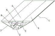
fig. 1 is a schematic perspective view of the present invention;
fig. 2 is a schematic view of the structure of the present invention;
in the figure: 1. a box girder body; 2. a bottom support beam; 3. side support beams; 4. a side beam face; 5. a middle beam surface; 6. supporting the inner beam core; 7. a side edge protection beam; 8. a steel rod; 9. and (4) pulling the steel cable.
Detailed Description
The technical solutions in the embodiments of the present invention will be described clearly and completely with reference to the accompanying drawings in the embodiments of the present invention, and it is obvious that the described embodiments are only some embodiments of the present invention, not all embodiments. Based on the embodiments in the present invention, all other embodiments obtained by a person skilled in the art without creative work belong to the protection scope of the present invention.
Examples
Referring to fig. 1-2, the present invention provides a technical solution: a novel box beam comprises a box beam body 1, wherein the box beam body 1 comprises a bottom supporting beam 2, a side supporting beam 3, a side beam surface 4 and a middle beam surface 5, the side supporting beam 3 is integrally formed at two side edges of the bottom supporting beam 2 by pouring, the side beam surface 4 is integrally formed at the upper end of the side supporting beam 3 by pouring, the middle beam surface 5 is integrally formed at the middle part of the side beam surface 4 by pouring, a supporting inner beam core 6 is integrally formed between the bottom supporting beam 2, the side supporting beam 3 and the middle beam surface 5 by pouring, a side protective beam 7 is integrally formed between the bottom supporting beam 2 and the side beam surface 4 by pouring, steel rods 8 and the bottom supporting beam 2 are embedded at the joint of the bottom supporting beam 2 and the side supporting beam 3 and the joint of the side supporting beam 3 and the side beam surface 4, the side supporting beam 3, the side beam surface 4, the middle beam surface 5, the supporting inner beam core 6 and the side protective beam 7 are all internally provided with a traction steel cable 9.
In this embodiment, through the integrally formed bottom supporting beam 2, the side supporting beam 3, the side beam surface 4 and the middle beam surface 5, the stability of the structure of the box girder body 1 is increased, and the production of the box girder body 1 is facilitated, meanwhile, the bottom supporting beam 2, the formed supporting inner beam core 6 is poured between the side supporting beam 3 and the middle beam surface 5, the stability of the connection between the bottom supporting beam 2, the side supporting beam 3 and the middle beam surface 5 is increased, and the strength of the structure of the box girder body 1 is improved, and meanwhile, the formed side protecting beam 7 is poured between the bottom supporting beam 2 and the side beam surface 4, and the stability of the side beam surface 4 is increased, so that the box girder body 1 is formed into an isosceles parallel box structure, and meanwhile, the steel rods 8 embedded inside the bottom supporting beam 2, the side supporting beam 3 and the side beam surface 4 are used as a base material, so that the firmness of the box girder body 1 is, Side supporting beam 3, side beam face 4, well beam face 5, support inner beam core 6 and the interior tractive cable wire 9 of 7 internally mounted of side guard beam have improved the stability that box girder body 1 is the box girder structure.
Specifically, the bottom support beam 2 and the side support beam 3 are both plate-shaped structures, and the included angle between the bottom support beam 2 and the side support beam 3 is 135 degrees.
In this embodiment, the bottom support beam 2 and the side support beam 3 both having a plate-like structure, and the included angle between the bottom support beam 2 and the side support beam 3 is 135 degrees, so that the bottom support beam 2 supports the side beam surface 4 and the middle beam surface 5 through the side support beam 3.
Specifically, the lower surface of the side beam surface 4 is an arc surface-shaped structure, and the upper surface of the side beam surface 4 and the upper surface of the middle beam surface 5 are on the same horizontal plane.
In this embodiment, the side beam surface 4 having the arc-surface-shaped lower surface increases the contact area between the side beam surface 4 and the side supporting beam 3, and the upper surface of the side beam surface 4 and the upper surface of the middle beam surface 5 are located on the same horizontal plane, so that the side supporting beam 3 supports the side beam surface 4 and the middle beam surface 5.
Specifically, the supporting inner beam core 6 is of a large-shaped structure, the supporting inner beam core 6 is provided with five support legs, the four support legs for supporting the inner beam core 6 and the side supporting beam 3 are integrally formed, and the other support leg for supporting the inner beam core 6 and the middle beam surface 5 are integrally formed.
In this embodiment, through the support inner beam core 6 that is "big" font structure, four stabilizer blades and the side supporting beam 3 integrated into one piece that support inner beam core 6 simultaneously, another stabilizer blade and the well roof beam face 5 integrated into one piece that support inner beam core 6 have increased the stability of case roof beam body 1 structure, have improved the firm nature of being connected between end supporting beam 2, side supporting beam 3 and the well roof beam face 5.
Specifically, the side protection beam 7 is of a plate-shaped structure, the bottom support beam 2, the side beam surface 4, the middle beam surface 5 and the side protection beam 7 form an isosceles parallelogram, and an included angle between the side protection beam 7 and the bottom support beam 2 is 160 degrees.
In this embodiment, the included angle between the side protection beam 7 and the bottom support beam 2 is 160 degrees, so that the side protection beam 7 can protect the side support beam 3 and the side beam surface 4.
Specifically, the pulling steel cable 9 is a flexible steel structure, and the pulling steel cable 9 is welded on the surfaces of the side protective beam 7 and the steel skeleton inside the box girder body 1.
In this embodiment, through the tractive cable 9 that is flexible steel construction, give tractive cable 9 to weld on the surface of side protective beam 7 and the inside steel skeleton of box girder body 1 simultaneously, increased the intensity of box girder body 1 structure.
The utility model discloses a theory of operation and use flow: during the use, 8 welding steel poles in the suitable position department of box girder steel skeleton of case, and draw-off cable wire 9 respectively with 8 steel poles and steel skeleton welded fastening, place the steel skeleton inside the mould, and pour into the concrete into at the mould inside, make end supporting beam 2, side supporting beam 3, side beam face 4, well roof beam face 5, support inner beam core 6 and side guard beam 7 integrated into one piece, make end supporting beam 2, constitute isosceles parallelogram between side supporting beam 3 and the well roof beam face 5, end supporting beam 2, side roof beam face 4, constitute isosceles parallelogram between well roof beam face 5 and the side guard beam 7.
Finally, it should be noted that: although the present invention has been described in detail with reference to the foregoing embodiments, it will be apparent to those skilled in the art that modifications may be made to the embodiments described in the foregoing embodiments, or equivalents may be substituted for elements thereof. Any modification, equivalent replacement, or improvement made within the spirit and principle of the present invention should be included in the protection scope of the present invention.
Claims (6)
1. The utility model provides a novel box girder, includes box girder body (1), its characterized in that: the box girder body (1) comprises a bottom supporting beam (2), side supporting beams (3), side beam faces (4) and middle beam faces (5), wherein the side supporting beams (3) are arranged at two side edges of the bottom supporting beam (2) through pouring of an integrated body, the side beam faces (4) are arranged at the upper ends of the side supporting beams (3) through pouring of an integrated body, the middle beam faces (5) are arranged at the middle parts of the side beam faces (4) through pouring of an integrated body, supporting inner beam cores (6) are arranged between the bottom supporting beam (2), the side supporting beams (3) and the middle beam faces (5) through pouring of an integrated body, side protecting beams (7) are arranged between the bottom supporting beam (2) and the side beam faces (4) through pouring of an integrated body, steel rods (8) are embedded at the joints of the bottom supporting beam (2) and the side supporting beam (3) and the joints of the side supporting beam (3) and the side beam faces (4), and traction steel cables (9) are arranged in the bottom supporting beam (2), the side supporting beam (3), the side beam surface (4), the middle beam surface (5), the supporting inner beam core (6) and the side protective beam (7).
2. A novel box beam as claimed in claim 1, wherein: the bottom support beam (2) and the side support beam (3) are both plate-shaped structures, and an included angle between the bottom support beam (2) and the side support beam (3) is 135 degrees.
3. A novel box beam as claimed in claim 1, wherein: the lower surface of the side beam surface (4) is of an arc surface-shaped structure, and the upper surface of the side beam surface (4) and the upper surface of the middle beam surface (5) are positioned on the same horizontal plane.
4. A novel box beam as claimed in claim 1, wherein: the supporting inner beam core (6) is of a large-shaped structure, the supporting inner beam core (6) is provided with five support legs, the four support legs of the supporting inner beam core (6) are integrally formed with the side supporting beam (3), and the other support leg of the supporting inner beam core (6) is integrally formed with the middle beam surface (5).
5. A novel box beam as claimed in claim 1, wherein: the side protection beam (7) is of a plate-shaped structure, the bottom support beam (2), the side beam surface (4), the middle beam surface (5) and the side protection beam (7) form an isosceles parallelogram, and an included angle between the side protection beam (7) and the bottom support beam (2) is 160 degrees.
6. A novel box beam as claimed in claim 1, wherein: the traction steel cable (9) is of a flexible steel structure, and the traction steel cable (9) is welded on the surfaces of the steel skeleton inside the side protective beam (7) and the box girder body (1).
Priority Applications (1)
| Application Number | Priority Date | Filing Date | Title |
|---|---|---|---|
| CN201921262046.5U CN210561663U (en) | 2019-08-06 | 2019-08-06 | Novel box-shaped beam |
Applications Claiming Priority (1)
| Application Number | Priority Date | Filing Date | Title |
|---|---|---|---|
| CN201921262046.5U CN210561663U (en) | 2019-08-06 | 2019-08-06 | Novel box-shaped beam |
Publications (1)
| Publication Number | Publication Date |
|---|---|
| CN210561663U true CN210561663U (en) | 2020-05-19 |
Family
ID=70638155
Family Applications (1)
| Application Number | Title | Priority Date | Filing Date |
|---|---|---|---|
| CN201921262046.5U Expired - Fee Related CN210561663U (en) | 2019-08-06 | 2019-08-06 | Novel box-shaped beam |
Country Status (1)
| Country | Link |
|---|---|
| CN (1) | CN210561663U (en) |
-
2019
- 2019-08-06 CN CN201921262046.5U patent/CN210561663U/en not_active Expired - Fee Related
Similar Documents
| Publication | Publication Date | Title |
|---|---|---|
| CN203188589U (en) | Rigid-frame continuous beam zero block construction bracket supporting system | |
| CN215329323U (en) | Light combined pier hoisted in small tonnage | |
| CN106638314A (en) | Pylon cross beam non-floor stand and pylon cross beam construction method | |
| CN105625186A (en) | Method for constructing large-section concrete Y-shaped column | |
| CN100545392C (en) | The construction method of hoop gusset plate and its suspended ceiling keel | |
| CN214657764U (en) | Box truss structure | |
| CN209685126U (en) | A kind of steel vestibule integrally promotes lifting lug device | |
| CN211473320U (en) | Tool type external hanging rack for corridor | |
| CN215479288U (en) | Truss portal crane with inverted triangular main beam structure | |
| CN114673074B (en) | Multipurpose standard H-shaped steel tower of cable lifting system | |
| CN213772978U (en) | Wet seam hanging die for prefabricated bent cap | |
| CN215164725U (en) | A stereotyped arc-shaped wood formwork support structure for cast-in-situ box beams of bridges | |
| CN212954025U (en) | Detachable tower crane sleeve frame | |
| CN210420839U (en) | A kind of ramp bridge steel structure | |
| CN211772739U (en) | Concrete box girder | |
| CN206127895U (en) | Cable tower crossbeam does not have floor stand and cable tower crossbeam construction system | |
| CN209260529U (en) | A new type of composite truss beam | |
| CN206418388U (en) | Suspension structure system for prefabricated middle beam installation of long-span steel tie-bar arch bridge | |
| CN217499974U (en) | Device for bridge closure construction | |
| CN222614803U (en) | Novel concrete dam crest working platform | |
| CN220789757U (en) | Manual hole digging pile lifting frame for railway business line | |
| CN224002303U (en) | Steel corridor lifting platform device | |
| CN217897288U (en) | Bearing type overhanging support structure for constructing suspended beam | |
| CN216336260U (en) | Standard knot main chord member for tower crane | |
| CN216663824U (en) | Quick assembly rack for construction of bridge pier body reinforcing steel bars |
Legal Events
| Date | Code | Title | Description |
|---|---|---|---|
| GR01 | Patent grant | ||
| GR01 | Patent grant | ||
| CF01 | Termination of patent right due to non-payment of annual fee |
Granted publication date: 20200519 Termination date: 20210806 |
|
| CF01 | Termination of patent right due to non-payment of annual fee |