CN210551663U - Waste discharge mechanism for corrugated board production line - Google Patents
Waste discharge mechanism for corrugated board production line Download PDFInfo
- Publication number
- CN210551663U CN210551663U CN201921142230.6U CN201921142230U CN210551663U CN 210551663 U CN210551663 U CN 210551663U CN 201921142230 U CN201921142230 U CN 201921142230U CN 210551663 U CN210551663 U CN 210551663U
- Authority
- CN
- China
- Prior art keywords
- groups
- welded connection
- corrugated board
- production line
- dust
- Prior art date
- Legal status (The legal status is an assumption and is not a legal conclusion. Google has not performed a legal analysis and makes no representation as to the accuracy of the status listed.)
- Expired - Fee Related
Links
- 238000004519 manufacturing process Methods 0.000 title claims abstract description 15
- 230000007246 mechanism Effects 0.000 title claims abstract description 14
- 239000002699 waste material Substances 0.000 title claims abstract description 13
- 239000000428 dust Substances 0.000 claims abstract description 43
- 238000005520 cutting process Methods 0.000 claims abstract description 11
- 244000309464 bull Species 0.000 claims abstract description 10
- 238000010521 absorption reaction Methods 0.000 claims abstract description 8
- 238000003466 welding Methods 0.000 claims description 10
- 230000036541 health Effects 0.000 abstract description 4
- 230000006872 improvement Effects 0.000 abstract description 2
- 239000011087 paperboard Substances 0.000 description 3
- 239000010410 layer Substances 0.000 description 2
- 239000000123 paper Substances 0.000 description 2
- 230000009467 reduction Effects 0.000 description 2
- 239000000853 adhesive Substances 0.000 description 1
- 230000001070 adhesive effect Effects 0.000 description 1
- 230000004075 alteration Effects 0.000 description 1
- 230000009286 beneficial effect Effects 0.000 description 1
- 238000010586 diagram Methods 0.000 description 1
- 238000001125 extrusion Methods 0.000 description 1
- 239000011229 interlayer Substances 0.000 description 1
- 238000000034 method Methods 0.000 description 1
- 230000004048 modification Effects 0.000 description 1
- 238000012986 modification Methods 0.000 description 1
- 230000008569 process Effects 0.000 description 1
- 238000006467 substitution reaction Methods 0.000 description 1
Images

Landscapes
- Refuse Collection And Transfer (AREA)
Abstract
The utility model discloses a waste discharge mechanism for corrugated board production line, including square case, the upper surface welded connection of square case has two sets of first support columns, and two sets of the free end welded connection of first support column has the roof, the utility model discloses the piston rod of cylinder drives the cutting knife downstream, and the rotation of servo motor output shaft realizes that the cutting knife cuts corrugated board, and the dust that produces when cutting corrugated board is sucked into the dust bag by dust absorption fan, effectively prevents the environment around the dust pollution, has protected operator's health; the rotation of first bull stick realizes that the second backup pad rotates on the slide bar, realizes the slope of second backup pad, and the limiting plate makes the second backup pad can be on a parallel with square incasement, makes the corrugated container board sweeps in the second backup pad roll the inner chamber of square case, and the effectual corrugated container board sweeps that prevents is piled up at square case's upper surface, great improvement work efficiency.
Description
Technical Field
The utility model belongs to the technical field of the exhaust equipment, concretely relates to waste discharge mechanism for corrugated board production line.
Background
Corrugated board is a multi-layer adhesive body, which is composed of at least one wave-shaped core paper interlayer and one layer of paper board. It has high mechanical strength and can resist collision and falling in the process of transportation. The actual performance of a corrugated box depends on three factors, the characteristics of the core paper and board, and the structure of the box itself.
When the corrugated board is cut on a production line at present, a large amount of dust is generated, the dust can pollute the surrounding environment, and the health of workers can be seriously influenced when the workers work in the environment for a long time; and the sweeps that the cutting produced are piled up and can influence the job schedule on the workstation, and these sweeps are cleared up to the manual work, great reduction work efficiency.
SUMMERY OF THE UTILITY MODEL
The utility model aims to provide a waste discharge mechanism for a corrugated board production line, which aims to solve the problems that a great deal of dust is generated when the corrugated board production line is cut at present, the dust can pollute the surrounding environment, and the health of workers can be seriously influenced when the workers work in the environment for a long time; and the sweeps that the cutting produced are piled up and can influence the job schedule on the workstation, and these sweeps are cleared up to the manual work, great reduction work efficiency's problem.
In order to achieve the above object, the utility model provides a following technical scheme: a waste discharge mechanism for a corrugated board production line comprises a square box, wherein two groups of first supporting columns are welded on the upper surface of the square box, a top plate is welded on the free end parts of the two groups of first supporting columns, an air cylinder is fixedly arranged on the upper surface of the top plate through bolts, a first supporting plate is fixedly arranged at the tail end of a piston rod of the air cylinder through bolts, a servo motor is fixedly arranged on the lower surface of the first supporting plate through bolts, two groups of vertical plates are welded on the upper surface of the first supporting plate, two groups of first bearings are arranged on the two groups of vertical plates, a connecting shaft is welded on the inner ring of the two groups of first bearings, two groups of cutting knives are fixedly arranged on the connecting shaft through bolts, a second bevel gear is welded on the connecting shaft, and a first bevel gear is welded on the output shaft of the servo, the first bevel gear and the second bevel gear are connected in a meshed manner, the lower surface of the first supporting plate is fixedly provided with a dust collection fan through a bolt, a dust collection bag is sleeved on a dust outlet pipe of the dust collection fan, two groups of bearing seats and limiting plates are welded on the inner surface of the square box, threaded rods are welded on the inner ring of the bearing seats, a second bearing is arranged on the square box, a first rotating rod is welded on the inner ring of the second bearing, a hand wheel is welded on the end part of the free end of the first rotating rod, a third bevel gear is welded on the first rotating rod, a fourth bevel gear is welded on the threaded rod, the third bevel gear is connected with the fourth bevel gear in a meshed manner, a threaded sleeve is connected on the threaded rod, a first fixing block is welded on the threaded sleeve, and a sliding rod is welded on the square box, the slide bar is rotatably connected with a second supporting plate, the lower surface of the second supporting plate is connected with a second fixed block in a welding mode, and a second rotating rod is rotatably connected between the first fixed block and the second fixed block.
Preferably, the lower surface of the square box is connected with four groups of second supporting columns in a welding mode, and the four groups of second supporting columns are arranged at four corners of the lower surface of the square box.
Preferably, a rubber support is adhered to the lower surface of the second support column, and the upper surface of the rubber support completely covers the lower surface of the second support column.
Preferably, the dust suction pipe of the dust suction fan is sleeved with an air guide cover, and the air guide cover is of a funnel-shaped structure.
Preferably, the square box is fixedly provided with a double door through a hinge, and the double door is provided with a door handle.
Preferably, the outer wall of the square box is welded with two groups of handles, and the two groups of handles are symmetrically arranged.
Compared with the prior art, the beneficial effects of the utility model are that:
1. the utility model discloses the upper surface welded connection of square case has two sets of first support columns, the free end welding connection of two sets of first support columns has the roof, the upper surface of roof has the cylinder through bolt fixed mounting, the piston rod end of cylinder has first backup pad through bolt fixed mounting, the lower surface of first backup pad has servo motor through bolt fixed mounting, the upper surface welded connection of first backup pad has two sets of risers, be provided with two sets of first bearings on two sets of risers, welded connection has the connecting axle on the inner ring of two sets of first bearings, there are two sets of cutting knife through bolt fixed mounting on the connecting axle, welded connection has second conical gear on the connecting axle, welded connection has first conical gear on the output shaft of servo motor, first conical gear and second conical gear mesh are connected, the lower surface of first backup pad has the dust absorption fan through bolt fixed mounting, the cover is equipped with the dust bag on dust exhaust pipe of dust absorption fan, and the piston rod of cylinder drives the cutter downstream, and the rotation of servo motor output shaft realizes that the cutter cuts corrugated container board, and produced dust is inhaled the dust bag by dust absorption fan when cutting corrugated container board in, and the effectual environment that prevents around the dust pollution has protected that operator's is healthy.
2. The utility model discloses welded connection has two sets of bearing frames and limiting plate on the internal surface of square case, welded connection has the threaded rod on the inner ring of two sets of bearing frames, square case is provided with the second bearing, welded connection has the first bull stick on the inner ring of second bearing, the free end welded connection of first bull stick has the hand wheel, welded connection has the third conical gear on the first bull stick, welded connection has the fourth conical gear on the threaded rod, third conical gear and fourth conical gear meshing connection, threaded connection has the thread bush on the threaded rod, welded connection has the first fixed block on the thread bush, welded connection has the slide bar on square case, rotate on the slide bar and be connected with the second backup pad, the lower surface welded connection of second backup pad has the second fixed block, rotate between first fixed block and the second fixed block and be connected with the second bull stick, rotatory hand wheel, the rotation of first bull stick realizes that the second backup pad rotates on the slide bar, realize the slope of second backup pad, the limiting plate makes the second backup pad can be on a parallel with square incasement, makes the corrugated container board sweeps in the second backup pad roll and falls into the inner chamber of square case, and the effectual corrugated container board sweeps that prevents is piled up at the upper surface of square case, great improvement work efficiency.
Drawings
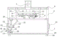
Fig. 1 is a schematic structural view of the present invention;
fig. 2 is a cross-sectional view of the present invention;
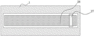
fig. 3 is a relationship diagram of the second supporting plate and the sliding rod according to the present invention.
In the figure: 1. a square box; 2. a first support column; 3. a cylinder; 4. a servo motor; 5. a first support plate; 6. a vertical plate; 7. a first bearing; 8. a top plate; 9. a connecting shaft; 10. a cutting knife; 11. a first bevel gear; 12. a second bevel gear; 13. a dust collection fan; 14. a dust collection bag; 15. a bearing seat; 16. a second bearing; 17. a first rotating lever; 18. a hand wheel; 19. a third bevel gear; 20. a fourth bevel gear; 21. a threaded rod; 22. a limiting plate; 23. a threaded sleeve; 24. a first fixed block; 25. a second rotating rod; 26. a second fixed block; 27. a slide bar; 28. a second support plate; 29. a second support column; 30. a rubber support; 31. a wind scooper; 32. double doors are opened; 33. a handle; 34. a door handle.
Detailed Description
The technical solutions in the embodiments of the present invention will be described clearly and completely with reference to the accompanying drawings in the embodiments of the present invention, and it is obvious that the described embodiments are only some embodiments of the present invention, not all embodiments. Based on the embodiments in the present invention, all other embodiments obtained by a person skilled in the art without creative work belong to the protection scope of the present invention.
Referring to fig. 1-3, the present invention provides a technical solution: a waste discharge mechanism for a corrugated board production line comprises a square box 1, wherein two groups of first supporting columns 2 are welded and connected on the upper surface of the square box 1, the free end parts of the two groups of first supporting columns 2 are welded and connected with a top plate 8, an air cylinder 3 is fixedly arranged on the upper surface of the top plate 8 through bolts, a first supporting plate 5 is fixedly arranged at the tail end of a piston rod of the air cylinder 3 through bolts, a servo motor 4 is fixedly arranged on the lower surface of the first supporting plate 5 through bolts, two groups of vertical plates 6 are welded and connected on the upper surface of the first supporting plate 5, two groups of first bearings 7 are arranged on the two groups of vertical plates 6, a connecting shaft 9 is welded and connected on the inner rings of the two groups of first bearings 7, two groups of cutting knives 10 are fixedly arranged on the connecting shaft 9 through bolts, a second bevel gear 12 is welded and connected, a first bevel gear 11 is meshed with a second bevel gear 12, a dust collection fan 13 is fixedly arranged on the lower surface of a first supporting plate 5 through bolts, a dust collection bag 14 is sleeved on a dust outlet pipe of the dust collection fan 13, two groups of bearing seats 15 and a limiting plate 22 are welded on the inner surface of a square box 1, threaded rods 21 are welded on the inner rings of the two groups of bearing seats 15, a second bearing 16 is arranged on the square box 1, a first rotating rod 17 is welded on the inner ring of the second bearing 16, a hand wheel 18 is welded on the free end of the first rotating rod 17, a third bevel gear 19 is welded on the first rotating rod 17, a fourth bevel gear 20 is welded on the threaded rod 21, the third bevel gear 19 is meshed with the fourth bevel gear 20, a threaded sleeve 23 is connected on the threaded rod 21, a first fixing block 24 is welded on the threaded sleeve 23, and a sliding rod 27 is welded on the square box 1, the slide bar 27 is rotatably connected with a second support plate 28, the lower surface of the second support plate 28 is connected with a second fixed block 26 in a welding mode, and a second rotating rod 25 is rotatably connected between the first fixed block 24 and the second fixed block 26.
Specifically, four groups of second support columns 29 are welded and connected to the lower surface of the square box 1, and the four groups of second support columns 29 are arranged at four corners of the lower surface of the square box 1, so that the lower surface of the square box 1 is far away from the ground, and stains on the ground are prevented from corroding the lower surface of the square box 1.
Specifically, a rubber support 30 is adhered to the lower surface of the second support column 29, the upper surface of the rubber support 30 completely covers the lower surface of the second support column 29, and the rubber support 30 protects the ground from being damaged by extrusion.
Specifically, the dust suction pipe of the dust suction fan 13 is sleeved with an air guide cover 31, and the air guide cover 31 is of a funnel-shaped structure, so that dust generated when the corrugated board is cut can be sucked into the dust collection bag 14 more quickly.
Specifically, two door 32 that open the door through hinge fixed mounting on the square case 1, two are provided with door handle 34 on the door 32, are convenient for collect the corrugated container board sweeps in the square case 1 inner chamber.
Specifically, welded connection has two sets of handles 33 on the outer wall of square case 1, and two sets of handles 33 symmetrical settings are convenient for to dragging or carrying of this mechanism of wasting discharge.
The working principle is as follows: the cylinder 3, the servo motor 4 and the dust absorption fan 13 are started, a piston rod of the cylinder 3 drives the cutter 10 to move downwards, the cutter 10 cuts the corrugated board through rotation of an output shaft of the servo motor 4, and dust generated when the corrugated board is cut is absorbed into the dust collection bag 14 through the dust absorption fan 13, so that the dust is effectively prevented from polluting the surrounding environment, and the body health of an operator is protected; the hand wheel 18 is rotated, the second supporting plate 28 is rotated on the sliding rod 27 by the rotation of the first rotating rod 17, the second supporting plate 28 is inclined, the limiting plate 22 enables the second supporting plate 28 to be parallel to the square box 1, corrugated paper board scraps on the second supporting plate 28 are rolled into the inner cavity of the square box 1, the corrugated paper board scraps are effectively prevented from being accumulated on the upper surface of the square box 1, and the working efficiency is greatly improved.
Although embodiments of the present invention have been shown and described, it will be appreciated by those skilled in the art that changes, modifications, substitutions and alterations can be made in these embodiments without departing from the principles and spirit of the invention, the scope of which is defined in the appended claims and their equivalents.
Claims (6)
1. The utility model provides a waste discharge mechanism for corrugated board production line, includes square case (1), its characterized in that: the upper surface of the square box (1) is connected with two groups of first supporting columns (2) in a welding manner, the free end parts of the two groups of first supporting columns (2) are connected with a top plate (8) in a welding manner, the upper surface of the top plate (8) is provided with a cylinder (3) through bolt fixing, the tail end of a piston rod of the cylinder (3) is provided with a first supporting plate (5) through bolt fixing, the lower surface of the first supporting plate (5) is provided with a servo motor (4) through bolt fixing, the upper surface of the first supporting plate (5) is connected with two groups of vertical plates (6) in a welding manner, the two groups of vertical plates (6) are provided with two groups of first bearings (7), the inner rings of the two groups of first bearings (7) are connected with a connecting shaft (9) in a welding manner, the connecting shaft (9) is provided with two groups of cutting knives (, welded connection has first conical gear (11) on the output shaft of servo motor (4), first conical gear (11) and second conical gear (12) meshing connection, there is dust absorption fan (13) lower surface of first backup pad (5) through bolt fixed mounting, the cover is equipped with dust bag (14) on the play dirt pipe of dust absorption fan (13), welded connection has two sets of bearing frame (15) and limiting plate (22) on the internal surface of square case (1), two sets of welded connection has threaded rod (21) on the inner ring of bearing frame (15), be provided with second bearing (16) on square case (1), welded connection has first bull stick (17) on the inner ring of second bearing (16), the free end welded connection of first bull stick (17) has hand wheel (18), welded connection has third conical gear (19) on first bull stick (17), welded connection has fourth conical gear (20) on threaded rod (21), third conical gear (19) and fourth conical gear (20) meshing connection, threaded connection has thread bush (23) on threaded rod (21), welded connection has first fixed block (24) on thread bush (23), welded connection has slide bar (27) on square case (1), it is connected with second backup pad (28) to rotate on slide bar (27), the lower surface welded connection of second backup pad (28) has second fixed block (26), it is connected with second bull stick (25) to rotate between first fixed block (24) and second fixed block (26).
2. A waste discharge mechanism for a corrugated board production line as claimed in claim 1, wherein: the lower surface of the square box (1) is connected with four groups of second supporting columns (29) in a welding mode, and the four groups of second supporting columns (29) are arranged at four corners of the lower surface of the square box (1).
3. A waste discharge mechanism for a corrugated board production line as claimed in claim 2, wherein: a rubber support (30) is adhered to the lower surface of the second supporting column (29), and the upper surface of the rubber support (30) completely covers the lower surface of the second supporting column (29).
4. A waste discharge mechanism for a corrugated board production line as claimed in claim 1, wherein: the dust collection fan is characterized in that a dust collection pipe of the dust collection fan (13) is sleeved with an air guide cover (31), and the air guide cover (31) is of a funnel-shaped structure.
5. A waste discharge mechanism for a corrugated board production line as claimed in claim 1, wherein: the square box (1) is fixedly provided with a double door (32) through a hinge, and the double door (32) is provided with a door handle (34).
6. A waste discharge mechanism for a corrugated board production line as claimed in claim 1, wherein: the outer wall of the square box (1) is connected with two groups of handles (33) in a welding mode, and the two groups of handles (33) are arranged symmetrically.
Priority Applications (1)
| Application Number | Priority Date | Filing Date | Title |
|---|---|---|---|
| CN201921142230.6U CN210551663U (en) | 2019-07-19 | 2019-07-19 | Waste discharge mechanism for corrugated board production line |
Applications Claiming Priority (1)
| Application Number | Priority Date | Filing Date | Title |
|---|---|---|---|
| CN201921142230.6U CN210551663U (en) | 2019-07-19 | 2019-07-19 | Waste discharge mechanism for corrugated board production line |
Publications (1)
| Publication Number | Publication Date |
|---|---|
| CN210551663U true CN210551663U (en) | 2020-05-19 |
Family
ID=70628041
Family Applications (1)
| Application Number | Title | Priority Date | Filing Date |
|---|---|---|---|
| CN201921142230.6U Expired - Fee Related CN210551663U (en) | 2019-07-19 | 2019-07-19 | Waste discharge mechanism for corrugated board production line |
Country Status (1)
| Country | Link |
|---|---|
| CN (1) | CN210551663U (en) |
Cited By (1)
| Publication number | Priority date | Publication date | Assignee | Title |
|---|---|---|---|---|
| CN116198169A (en) * | 2022-12-30 | 2023-06-02 | 杭州萧山联发包装有限公司 | Stretchable corrugated case rapid forming equipment and method thereof |
-
2019
- 2019-07-19 CN CN201921142230.6U patent/CN210551663U/en not_active Expired - Fee Related
Cited By (1)
| Publication number | Priority date | Publication date | Assignee | Title |
|---|---|---|---|---|
| CN116198169A (en) * | 2022-12-30 | 2023-06-02 | 杭州萧山联发包装有限公司 | Stretchable corrugated case rapid forming equipment and method thereof |
Similar Documents
| Publication | Publication Date | Title |
|---|---|---|
| CN105643730A (en) | Waste timber recycling device | |
| CN220737876U (en) | Manufacturing device for preparing recycled aggregate from construction waste | |
| CN214863927U (en) | Building rubbish circulation reducing mechanism | |
| CN210684573U (en) | Leaf collection truck for road | |
| CN213674526U (en) | Cutting auxiliary device for furniture design | |
| CN211678009U (en) | An environmentally friendly garbage crushing device with dust reduction function | |
| CN221659713U (en) | ALC panel processing cutting device | |
| CN221656679U (en) | A building rubbish collection device for construction | |
| CN218051607U (en) | Fan blade tip milling device | |
| CN211490704U (en) | Electrode grounding metal sheet cuts dust collector | |
| CN108970679B (en) | A breaker for abandonment wire pole recycle | |
| CN215087467U (en) | A construction waste crushing and processing device | |
| CN209501779U (en) | A kind of novel civil engineering work waste treatment device | |
| CN214683462U (en) | Household garbage treatment integrated equipment based on nano-wave | |
| CN208661327U (en) | A kind of building waste grinding device easy to repair | |
| CN210332968U (en) | Smashing device for plastic woven bags | |
| CN206690237U (en) | A kind of New-type wood cutting machine with garbage collection function | |
| CN210233379U (en) | Waste collecting device is used in production and processing of wooden curtain pole | |
| CN221850363U (en) | Drinking water filter element forming and cutting device | |
| CN210935318U (en) | High-efficient breaker for building | |
| CN219003284U (en) | A construction waste crushing device | |
| CN221452705U (en) | Municipal works management environmental protection garbage disposer | |
| CN221818846U (en) | Composite floor cutting device | |
| CN222161416U (en) | Irrigation and water conservancy irrigation ditch cleaning device | |
| CN215312845U (en) | Building rubbish crushing apparatus for building engineering |
Legal Events
| Date | Code | Title | Description |
|---|---|---|---|
| GR01 | Patent grant | ||
| GR01 | Patent grant | ||
| CF01 | Termination of patent right due to non-payment of annual fee | ||
| CF01 | Termination of patent right due to non-payment of annual fee |
Granted publication date: 20200519 Termination date: 20210719 |