CN210548231U - Perforating device for hardware mold manufacturing - Google Patents
Perforating device for hardware mold manufacturing Download PDFInfo
- Publication number
- CN210548231U CN210548231U CN201921038518.9U CN201921038518U CN210548231U CN 210548231 U CN210548231 U CN 210548231U CN 201921038518 U CN201921038518 U CN 201921038518U CN 210548231 U CN210548231 U CN 210548231U
- Authority
- CN
- China
- Prior art keywords
- electric telescopic
- telescopic column
- workbench
- clamp
- column
- Prior art date
- Legal status (The legal status is an assumption and is not a legal conclusion. Google has not performed a legal analysis and makes no representation as to the accuracy of the status listed.)
- Expired - Fee Related
Links
Images


Landscapes
- Perforating, Stamping-Out Or Severing By Means Other Than Cutting (AREA)
Abstract
The utility model discloses a punching device for manufacturing hardware moulds, which comprises a base, wherein the upper end of the base is provided with a workbench, the upper end of the workbench is provided with a supporting piece, the upper end of the workbench is provided with a supporting column, the top end of the supporting column is provided with a cross beam, the upper end of the beam is provided with a water pump, one side of the support column is provided with a first electric telescopic column, the output end of the first electric telescopic column is provided with a clamp, the top end of the clamp is provided with a first air cylinder, the output end of the first air cylinder penetrates through the top end of the clamp and is fixedly connected with a connecting plate, the connecting plate bottom is provided with the rubber pad, and the operator only needs the operation control box can accomplish the action of punching the hardware mould body, has realized the purpose that the full automatization was punched, has reached the purpose that makes hardware mould operation simple operation work efficiency high that punches, can effectually prevent the drill bit slope and the problem of the incline that punches appears.
Description
Technical Field
The utility model relates to a hardware mould processing technology field, in particular to perforating device is used in hardware mould manufacturing.
Background
In the prior art, a hardware mould is a part or a product with a required shape manufactured by pressing a metal material by using various presses and special tools arranged on the presses in industrial production, the special tools are collectively called as the hardware mould, and various tools and products used in daily production and life are as large as a base and a machine body shell of a machine tool and as small as a head screw, a button and shells of various household appliances, so that the shape of the mould determines the appearance of the product, and the processing quality and precision of the mould determine the quality of the product. Because the difference of the material of various products, outward appearance, specification and usage, the mould is divided into casting mould, forging mould, non-plastic moulds such as die mould, stamping die to and plastic mould, common hardware mould perforating device adopts the manual work to punch for the most, not only wastes time and energy, and efficiency is not high, and at the in-process that punches, raw and other materials can't be fixed, can't guarantee the accuracy of punching, so the utility model relates to a novel hardware mould perforating device.
Therefore, it is necessary to provide a punching device for manufacturing hardware molds to solve the above problems.
SUMMERY OF THE UTILITY MODEL
An object of the utility model is to provide a perforating device is used in hardware mould manufacturing to solve the problem that proposes among the above-mentioned background art.
In order to achieve the above object, the utility model provides a following technical scheme: the utility model provides a perforating device is used in hardware mould manufacturing, includes the base, its characterized in that: the upper end of the base is provided with a workbench, the upper end of the workbench is provided with a support piece, the upper end of the workbench is provided with a support column, the top end of the support column is provided with a crossbeam, the upper end of the crossbeam is provided with a water pump, one side of the support column is provided with a first electric telescopic column, the output end of the first electric telescopic column is provided with a clamp, the top end of the clamp is provided with a first air cylinder, the output end of the first air cylinder penetrates through the top end of the clamp and is fixedly connected with a connecting plate, the bottom end of the connecting plate is provided with a rubber pad, the upper end of the support column is provided with a support plate, one side of the support plate is fixedly provided with a second electric telescopic column, the other side of the support plate is fixedly provided with a control box, the output end, the drill bit is installed to the motor output, the motor lower extreme is equipped with stop device.
Preferably, the support member is provided with a groove in the middle.
Preferably, electric slide rails are arranged on two sides of the upper end of the workbench.
Preferably, the water pump, the first electric telescopic column, the second electric telescopic column, the third electric telescopic column, the motor and the electric slide rail are electrically connected with the control box.
The utility model discloses a technological effect and advantage:
the utility model discloses be convenient for to punching of hardware mould, enable the drill bit up-and-down motion, the operator only needs the operation control box can accomplish the action of punching the hardware mould body, has realized the purpose that the full automatization punched, has reached the purpose that makes hardware mould punching operation easy operation work efficiency high, can effectually prevent the drill bit slope and the oblique problem of punching appears.
Drawings
Fig. 1 is a front view of the present invention.
Fig. 2 is a side view of the present invention.
Fig. 3 is a top view of the support member of the present invention.
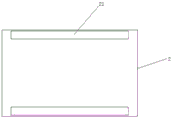
Fig. 4 is a top view of the working table of the present invention.
In the figure: 1. 2, 3, 4, 5, 6, 7, 8, 9, 10, 11, 12, 13, 14, 15, 16, 17.
Detailed Description
The technical solutions in the embodiments of the present invention will be described clearly and completely with reference to the accompanying drawings in the embodiments of the present invention, and it is obvious that the described embodiments are only some embodiments of the present invention, not all embodiments. Based on the embodiments in the present invention, all other embodiments obtained by a person skilled in the art without creative work belong to the protection scope of the present invention.
The utility model provides a perforating device is used in hardware mould manufacturing as shown in the figure, including base 1, its characterized in that: the upper end of the base 1 is provided with a workbench 2, the upper end of the workbench 2 is provided with a support piece 3, the upper end of the workbench 2 is provided with a support column 4, the top end of the support column 4 is provided with a crossbeam 5, the upper end of the crossbeam 5 is provided with a water pump 6, one side of the support column 4 is provided with a first electric telescopic column 7, the output end of the first electric telescopic column 7 is provided with a clamp 8, the top end of the clamp 8 is provided with a first air cylinder 9, the output end of the first air cylinder 9 penetrates through the top end of the clamp 8 and is fixedly connected with a connecting plate 10, the bottom end of the connecting plate 10 is provided with a rubber pad 11, the upper end of the support column 4 is provided with a support plate 22, one side of the support plate 22 is fixedly provided with a second electric telescopic column 13, the other side of, the electronic flexible post 15 of third is installed to 5 middle part lower extremes of crossbeam, the electronic flexible post 15 output of third is equipped with motor 16, drill bit 17 is installed to the 16 output of motor, 16 lower extremes of motor are equipped with stop device 18.
Further, in the above technical solution, a groove 23 is provided in the middle of the supporting member 3;
further, in the above technical solution, both sides of the upper end of the worktable 2 are provided with electric slide rails 21;
further, in the above technical solution, the water pump 6, the first electric telescopic column 7, the second electric telescopic column 13, the third electric telescopic column 15, the motor 16 and the electric slide rail 21 are all electrically connected to the control box 12.
Finally, it should be noted that: although the present invention has been described in detail with reference to the foregoing embodiments, it will be apparent to those skilled in the art that modifications and variations can be made in the embodiments or in part of the technical features of the embodiments without departing from the spirit and the scope of the invention.
Claims (4)
1. The utility model provides a perforating device for hardware mould manufacturing, includes base (1), its characterized in that: the automatic lifting device is characterized in that a workbench (2) is arranged at the upper end of the base (1), a support piece (3) is arranged at the upper end of the workbench (2), a support column (4) is arranged at the upper end of the workbench (2), a cross beam (5) is installed at the top end of the support column (4), a water pump (6) is installed at the upper end of the cross beam (5), a first electric telescopic column (7) is arranged on one side of the support column (4), a clamp (8) is arranged at the output end of the first electric telescopic column (7), a first air cylinder (9) is installed at the top end of the clamp (8), the output end of the first air cylinder (9) penetrates through the top end of the clamp (8) and is fixedly connected with a connecting plate (10), a rubber pad (11) is arranged at the bottom end of the connecting plate (10), a, and opposite side fixed mounting control box (12), second electric telescopic column (13) output is equipped with water pipe (14), high pressure nozzle (19) are installed to water pipe (14) bottom, third electric telescopic column (15) are installed to crossbeam (5) middle part lower extreme, third electric telescopic column (15) output is equipped with motor (16), drill bit (17) are installed to motor (16) output, motor (16) lower extreme is equipped with stop device (18).
2. The punching device for manufacturing the hardware die as claimed in claim 1, wherein the punching device comprises: the middle part of the support part (3) is provided with a groove (23).
3. The punching device for manufacturing the hardware die as claimed in claim 1, wherein the punching device comprises: and electric sliding rails (21) are arranged on two sides of the upper end of the workbench (2).
4. The punching device for manufacturing the hardware die as claimed in claim 1, wherein the punching device comprises: the water pump (6), the first electric telescopic column (7), the second electric telescopic column (13), the third electric telescopic column (15), the motor (16) and the electric sliding rail (21) are electrically connected with the control box (12).
Priority Applications (1)
| Application Number | Priority Date | Filing Date | Title |
|---|---|---|---|
| CN201921038518.9U CN210548231U (en) | 2019-07-05 | 2019-07-05 | Perforating device for hardware mold manufacturing |
Applications Claiming Priority (1)
| Application Number | Priority Date | Filing Date | Title |
|---|---|---|---|
| CN201921038518.9U CN210548231U (en) | 2019-07-05 | 2019-07-05 | Perforating device for hardware mold manufacturing |
Publications (1)
| Publication Number | Publication Date |
|---|---|
| CN210548231U true CN210548231U (en) | 2020-05-19 |
Family
ID=70674085
Family Applications (1)
| Application Number | Title | Priority Date | Filing Date |
|---|---|---|---|
| CN201921038518.9U Expired - Fee Related CN210548231U (en) | 2019-07-05 | 2019-07-05 | Perforating device for hardware mold manufacturing |
Country Status (1)
| Country | Link |
|---|---|
| CN (1) | CN210548231U (en) |
Cited By (1)
| Publication number | Priority date | Publication date | Assignee | Title |
|---|---|---|---|---|
| CN110202182A (en) * | 2019-07-05 | 2019-09-06 | 深圳市精创科技有限公司 | Perforating device is used in a kind of manufacture of hardware dies |
-
2019
- 2019-07-05 CN CN201921038518.9U patent/CN210548231U/en not_active Expired - Fee Related
Cited By (1)
| Publication number | Priority date | Publication date | Assignee | Title |
|---|---|---|---|---|
| CN110202182A (en) * | 2019-07-05 | 2019-09-06 | 深圳市精创科技有限公司 | Perforating device is used in a kind of manufacture of hardware dies |
Similar Documents
| Publication | Publication Date | Title |
|---|---|---|
| CN210676615U (en) | Combined die safety protection device | |
| CN210548231U (en) | Perforating device for hardware mold manufacturing | |
| CN209792577U (en) | Hardware mould convenient to drawing of patterns | |
| CN211191593U (en) | Compound burring device of aluminium die casting | |
| CN209255560U (en) | Stamping device is used in a kind of production of auto parts and components | |
| CN208758449U (en) | A kind of manufacturing device of auto parts and components mold | |
| CN214814012U (en) | Punching die with automatic waste removing function | |
| CN213317216U (en) | Hardware piece pressing die | |
| CN103551851A (en) | Method and die for combined forming of parts of metal plate with protrusion structure at bottom | |
| CN207952411U (en) | A kind of separating type die | |
| CN111229901A (en) | Die stamping fixing device | |
| CN220805179U (en) | Stamping die for display frame production and processing | |
| CN204429990U (en) | A kind of double end compression mold | |
| CN219211251U (en) | Stamping equipment for elevator upper beam production | |
| CN211028325U (en) | Cutting mechanism for machining precision die | |
| CN214601492U (en) | Stamping die for continuous machining | |
| CN217665803U (en) | Double-channel continuous stamping die | |
| CN216938070U (en) | Casting processing punching machine | |
| CN220426533U (en) | Stamping die for stamping metal products | |
| CN219004584U (en) | Extrusion separation die for sintering jig | |
| CN220361877U (en) | Stamping die | |
| CN202239267U (en) | Tapping device in metal mold | |
| CN219616504U (en) | A mould for automobile parts | |
| CN214977128U (en) | Stamping die with quick demoulding function | |
| CN216266508U (en) | High-precision whole-circle outward circular cutting die |
Legal Events
| Date | Code | Title | Description |
|---|---|---|---|
| GR01 | Patent grant | ||
| GR01 | Patent grant | ||
| CF01 | Termination of patent right due to non-payment of annual fee |
Granted publication date: 20200519 Termination date: 20210705 |
|
| CF01 | Termination of patent right due to non-payment of annual fee |