CN210541742U - Anesthesia puncture auxiliary fixing device - Google Patents
Anesthesia puncture auxiliary fixing device Download PDFInfo
- Publication number
- CN210541742U CN210541742U CN201822016321.7U CN201822016321U CN210541742U CN 210541742 U CN210541742 U CN 210541742U CN 201822016321 U CN201822016321 U CN 201822016321U CN 210541742 U CN210541742 U CN 210541742U
- Authority
- CN
- China
- Prior art keywords
- needle tube
- sleeve
- needle
- cover
- fixed
- Prior art date
- Legal status (The legal status is an assumption and is not a legal conclusion. Google has not performed a legal analysis and makes no representation as to the accuracy of the status listed.)
- Expired - Fee Related
Links
Images


Abstract
The utility model discloses an anesthesia puncture auxiliary fixture, including needle tubing cover and stable cover, and needle tubing cover and stable cover swing joint, still have the fixed component of needle tubing with needle tubing cover matched with, the cover body outer wall of needle tubing cover is opened there are two at least guide ways, the tip of stable cover has two piece at least connecting rods, the tip of every connecting rod has the slider, cooperation through guide way and slider, needle tubing cover and stable cover swing joint, the fixed component of needle tubing includes the fixed cover body, the lower extreme of the fixed cover body has the shrouding, the shrouding is opened there is the through-hole, and the periphery that the shrouding is located the through-hole has annular link, the periphery of annular link has male thread, the cover body upper end inner wall of needle tubing cover has female thread, the fixed cover body passes through the annular link thread and installs the upper end at needle tubing cover, fixed internal. The utility model discloses it is rational in infrastructure, can be in the anesthesia puncture to assist medical personnel well.
Description
Technical Field
The utility model relates to an anesthesia puncture field especially relates to an auxiliary device when anesthesia puncture.
Background
Anesthesia puncture is often required to be carried out when clinical treatment of a hospital, most of surgical operations or examinations are required to be carried out under the state that a patient is anesthetized, due to the progress of the current society, anesthesia puncture is not blind detection by hands of medical personnel in the past, anesthesia puncture is carried out by simply depending on experience and anatomical landmarks, anesthesia puncture is carried out on the premise of ultrasonic visualization, the medical personnel can directly puncture a target point under image monitoring, the anesthesia effect and the success rate are greatly improved compared with the past, however, the medical personnel are controlled by hands only when puncturing a needle, the needle is easy to shake, puncture errors can be caused, and other tissues of the patient are easy to damage.
While the chinese patent CN207627385U discloses an anesthetic puncture fixer, which can provide guiding function when puncturing the needle, and avoid the needle body from skewing and shaking when the needle is inserted, but the structure is still a series of disadvantages when in actual use, firstly, the needle tube fixing part of the structure mainly uses four threaded rods to realize the purpose of clamping the needle tube, when in use, medical personnel needs to respectively select four threaded rods, so that the abutting block at the end part can abut against the tube body of the needle tube, the first procedure is more complicated, the fixing effect is poor, the needle tube is easy to be stressed and skewed, further, by adopting the fixing mode, the needle tube is difficult to be exactly positioned at the central position of the needle tube sleeve, if the needle tube is not at the central position, the medical personnel is difficult to be positioned when puncturing, errors are easy to be caused, further, the structure simply abuts against the body of a patient through the stabilizing sleeve, provides basic support during needle insertion, but during actual puncture, the needle insertion angle is not perpendicular to the needle insertion, but the needle insertion angle is provided, so that the stable cannula is difficult to abut against the body of a patient during operation.
SUMMERY OF THE UTILITY MODEL
The utility model aims at solving the defects existing in the prior art and providing an anesthesia puncture auxiliary fixing device.
In order to achieve the above purpose, the utility model adopts the following technical scheme:
the utility model provides an anesthesia puncture auxiliary fixture, including needle tube cover and stable cover, and needle tube cover and stable cover swing joint, still have the needle tube fixed component who cooperates with the needle tube cover, the cover body outer wall of needle tube cover is opened there are two at least guide ways, the tip of stable cover has two piece at least connecting rods, the tip of every connecting rod has the slider, cooperation through guide way and slider, needle tube cover and stable cover swing joint, the needle tube fixed component includes the fixed cover body, the lower extreme of the fixed cover body has the shrouding, the shrouding is opened there is the through-hole, and the periphery that the shrouding is located the through-hole has annular link, the periphery of annular link has the male thread, the cover body upper end inner wall of needle tube cover has the female thread, the fixed cover body passes through the annular link threaded mounting in the upper end of.
The clamping component comprises a fixed clamping block and a movable clamping block which are the same in structure, one side surface of each of the body parts of the fixed clamping block and the movable clamping block is provided with a fitting arc surface matched with an external needle tube, the other side surface of each of the body parts of the fixed clamping block is connected with the fixed sleeve body through a clamping block connecting rod, the clamping component further comprises an adjusting bolt, one end of the adjusting bolt penetrates through the fixed sleeve body to be connected with the movable clamping block, the sleeve body of the fixed sleeve body is further provided with a fixed nut sleeve matched with the adjusting bolt, the other end of the adjusting bolt is provided with a holding disc, the end part of the adjusting bolt is provided with a connecting cavity, and the adjusting bolt is connected with.
The other side surface of the block body of the movable clamping block is provided with a second connecting rod, the second connecting rod penetrates through a top plate of the connecting cavity to enter the connecting cavity, a rod body of the second connecting rod is provided with two balls, and the top plate is located between the two balls.
The front end of the sleeve body of the stabilizing sleeve is connected with the connecting ring through the connecting rib plate, the attaching ring matched with the connecting ring is further arranged, the connecting spring is arranged between the connecting ring and the attaching ring, and the lower end face of the attaching ring is provided with the silica gel ring.
The needle tube fixing component further comprises a needle tube fixing seat, the needle tube fixing seat comprises a fixing plate seat, the seat body of the fixing plate seat is provided with at least two insertion columns, the needle tube fixing seat further comprises a needle tube insertion seat, the lower end of the needle tube insertion seat is provided with insertion holes, and the needle tube insertion seat is fixedly arranged on the fixing plate seat through the cooperation of the insertion columns and the insertion holes.
The needle tube inserting seat is provided with an inserting cavity, the inner wall of the upper end of the needle tube inserting seat in the inserting cavity is provided with a female thread, and the fixed sleeve body is installed on the needle tube inserting seat through the annular connecting end thread.
The seat body of fixed plate seat is located the side of every cartridge post and is opened and to be placed the recess, still has and places recess matched with removable cover, and the label can be put into and place in the recess, and the side of label has to draw and draws the strip.
Compared with the prior art, the beneficial effects of the utility model are that:
the utility model discloses can provide the direction when the needle tubing injection in reliable fixed injection needle tubing, avoid the syringe needle to rock, improve the success rate of anesthesia, can also reliably place injection needle tubing before the puncture simultaneously with the puncture back, when conveniently taking, also make things convenient for medical personnel to accomodate when the operation, be difficult to cause medical accident.
Drawings
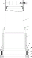
FIG. 1 is a schematic view showing the structural relationship among the condom body 7, the needle cannula cover 1 and the stabilizing cover 2;
fig. 2 is a schematic view of the structural relationship between the guide groove 4 and the slide block 6 of the present invention;
fig. 3 is a schematic structural view of the fixing sleeve 7 of the present invention;
fig. 4 is a schematic structural view of the fixing clamp 12 of the present invention;
fig. 5 is a schematic structural relationship diagram of the connection cavity 19 and the second connection rod 20 according to the present invention;
FIG. 6 is a schematic structural view of the needle cannula fixing member 3 of the present invention;
fig. 7 is a schematic view of the movable cover plate 34 and the label 35 of the present invention after being placed in the placement groove 33;
fig. 8 is a schematic structural diagram of the tag 35 of the present invention.
In the figure: the needle tube fixing device comprises a needle tube sleeve 1, a needle tube stabilizing sleeve 2, a needle tube fixing component 3, a guide groove 4, a connecting rod 5, a sliding block 6, a fixing sleeve body 7, a sealing plate 8, a through hole 9, an annular connecting end 10, a clamping component 11, a fixing clamping block 12, a movable clamping block 13, a joint cambered surface 14, a clamping block connecting rod 15, an adjusting bolt 16, a fixing nut sleeve 17, a holding disc 18, a connecting cavity 19, a second connecting rod 20, a ball 21, a connecting rib plate 22, a connecting ring 23, a joint ring 24, a connecting spring 25, a silica gel ring 26, a needle tube fixing seat 27, a fixing plate seat 28, a plug-in column 29, a needle tube plug-in seat 30, a plug-in hole 31, a needle tube inserting cavity 32, a placing groove 33, a movable.
Detailed Description
The technical solutions in the embodiments of the present invention will be described clearly and completely with reference to the accompanying drawings in the embodiments of the present invention, and it is obvious that the described embodiments are only some embodiments of the present invention, not all embodiments.
Referring to fig. 1-8, an auxiliary fixing device for anesthesia puncture comprises a needle cannula sleeve 1 and a stabilizing sleeve 2, wherein the needle cannula sleeve 1 is movably connected with the stabilizing sleeve 2, the needle cannula fixing member 3 matched with the needle cannula sleeve 1 is also provided, the outer wall of the body of the needle cannula sleeve 1 is provided with at least two guide grooves 4, the end of the stabilizing sleeve 2 is provided with at least two connecting rods 5, the end of each connecting rod 5 is provided with a slide block 6, the needle cannula sleeve 1 is movably connected with the stabilizing sleeve 2 through the matching of the guide grooves 4 and the slide block 6, the needle cannula fixing member 3 comprises a fixing sleeve body 7, the lower end of the fixing sleeve body 7 is provided with a seal plate 8, the seal plate 8 is provided with a through hole 9, the seal plate 8 is positioned at the periphery of the through hole 9 and is provided with an annular connecting end 10, the periphery of the annular connecting end 10 is provided with a male thread, the inner wall of the upper end, the fixed sleeve body 7 is internally provided with a clamping component 11. When the utility model is used, firstly, the needle cylinder is stretched into the inner cavity of the fixed sleeve body 7, the needle cylinder is clamped and fixed on the fixed sleeve body 7 through the clamping component 11, then the needle cylinder can be stretched into the inner cavity of the needle tube sleeve 1, at the moment, the fixed sleeve body 7 is installed at the upper end of the needle tube sleeve 1 through the annular connecting end 10 threads, thus the needle cylinder and the needle tube sleeve 1 are connected into a whole, then the stable sleeve 2 is placed at the body part needing puncturing by a patient according to a real-time image, at the moment, the slide block 6 at the end part of the connecting rod 5 can be stretched into the guide groove 4 of the needle tube sleeve 1 (the guide groove 4 and the connecting rod 5 can be respectively arranged at the two opposite ends of the needle tube sleeve 1 and the stable sleeve 2, thus, the guide effect is better, and in order to further improve the guide effect, the guide groove 4 can also be a dovetail groove), thus, when the, and needle tube sleeve 1 drives the cylinder motion, and the felting needle of cylinder passes the inner chamber of stabilizing sleeve 2 and pierces patient's health, just so can realize the stability of the action of inserting the needle through the cooperation of guide way 4 and slider 6, be difficult to crooked and skew when inserting the needle (needle tube sleeve 1 can all adopt transparent plastic to make with stabilizing sleeve 2 when in actual use, conveniently observes the position of cylinder in real time when the operation, and simultaneously for convenient operation, the internal diameter of stabilizing sleeve 2 can be greater than the external diameter of needle tube sleeve 1).
The clamping component 11 comprises a fixed clamping block 12 and a movable clamping block 13 which are identical in structure, one side surface of each of the body of the fixed clamping block 12 and the body of the movable clamping block 13 is provided with a fitting cambered surface 14 matched with an external needle tube, the other side surface of the body of the fixed clamping block 12 is connected with the fixed sleeve body 7 through a clamping block connecting rod 15, the clamping component 11 further comprises an adjusting bolt 16, one end of the adjusting bolt 16 penetrates through the fixed sleeve body 7 to be connected with the movable clamping block 13, the sleeve body of the fixed sleeve body 7 is further provided with a fixed nut sleeve 17 matched with the adjusting bolt 16, the other end of the adjusting bolt 16 is provided with a holding disc 18, the end part of the adjusting bolt 16 is provided with a connecting cavity 19, and the adjusting bolt 16 is connected with the movable clamping block. The clamping component 11 can ensure that the needle cylinder is concentric with the fixed sleeve body 7 and the needle sleeve 1 as much as possible, and the attaching cambered surface 14 can be attached to the outer wall of the needle tube, so that the needle tube can be reliably clamped by using the fixed clamping block 12 and the movable clamping block 13, the situation of deflection in use is avoided, the stability is ensured at first, and when the clamping component 11 is manufactured, the position of the fixed clamping block 12 can be set by taking the concentric position of the needle cylinder and the fixed sleeve body 7 as a reference, so that the concentric position of the needle cylinder and the fixed sleeve body 1 can be ensured when the needle cylinder is attached to the fixed clamping block 12, and then the needle cylinder is clamped and fixed by the movable clamping block 13.
The other side surface of the movable clamping block 13 is provided with a second connecting rod 20, the second connecting rod 20 penetrates through a top plate 37 of the connecting cavity 19 and enters the connecting cavity 19, the shaft of the second connecting rod 20 is provided with two balls 21, and the top plate 37 is positioned between the two balls 21. The advantage of such a structure is that the movable clamping block 13 can be connected with the connecting cavity 19 through the second connecting rod 20, and meanwhile, when the adjusting bolt 16 rotates, the movable clamping block 13 cannot be driven to rotate along with the adjusting bolt, so that the movable clamping block 13 and the fixed clamping block 12 can reliably clamp and fix the syringe.
The front end of the sleeve body of the stabilizing sleeve 2 is connected with a connecting ring 23 through a connecting rib plate 22, the stabilizing sleeve is also provided with a joint ring 24 matched with the connecting ring 23, a connecting spring 25 is arranged between the connecting ring 23 and the joint ring 24, and the lower end face of the joint ring 24 is provided with a silica gel ring 26. The benefit of structure like this lies in, when laminating ring 24 laminating is fixed in patient's health, stability sleeve 2 can realize the skew of self through coupling ring 23 and coupling spring 25, just so realized the adjustment of needle insertion angle, during the in-service use, laminating ring 24 can be fixed in order to realize through the laminating of silica gel circle 26 on patient's skin, simultaneously when the adjustment of needle insertion angle back that finishes, medical personnel just can be fixed in order to realize with the periphery of forefinger and thumb centre gripping coupling ring 23, medical personnel's another hand just can hold the needle tubing this moment and advance the needle and moved.
The needle tube fixing component 3 further comprises a needle tube fixing seat 27, the needle tube fixing seat 27 comprises a fixing plate seat 28, the seat body of the fixing plate seat 28 is provided with at least two insertion columns 29, the needle tube fixing seat 27 further comprises a needle tube insertion seat 30, the lower end of the needle tube insertion seat 30 is provided with insertion holes 31, and the needle tube insertion seat 30 is fixedly arranged on the fixing plate seat 28 through the matching of the insertion columns 29 and the insertion holes 31. The injection needle cylinder can be fixed by utilizing the needle tube fixing seat 27, so that the injection needle cylinder has fixed placing positions during preoperative preparation and in the operation process, each injection needle cylinder can be independently placed on the corresponding needle tube inserting seat 30, at least two needle tube inserting seats 30 can be placed on one fixing plate seat 28, the detachable structure is convenient to take, and the flexibility is high.
The needle tube cartridge 30 has an insertion cavity 32, the inner wall of the needle tube cartridge 30 at the upper end of the insertion cavity 32 has a female thread, and the fixed sleeve body 7 is threadedly mounted on the needle tube cartridge 30 through the annular connecting end 10. After the needle cylinder is arranged in the inner cavity of the fixed sleeve body 7, the front end of the needle cylinder can extend into the insertion cavity 32, and then the fixed sleeve body 7 can be installed on the needle tube insertion seat 30 in a threaded mode, so that the needle cylinder can be reliably fixed on the needle tube insertion seat 30, and the condition that the needle cylinder falls off cannot occur even in the process of transferring.
The side of the fixed plate seat 28, which is located on each insertion column 29, is provided with a placing groove 33 and a movable cover plate 34 which is matched with the placing groove 33, a label 35 can be placed in the placing groove 33, and the side of the label 35 is provided with a pulling strip 36. Label 35 can record the name of a drug in the syringe needle, information such as measurement, can not take place the mistake when guaranteeing to take the operation, and label 35 can be put into and place in the recess 33, removable cover 34 is put into and is placed in the recess 33 simultaneously, can cover fixed label 35, and when label 35 is put into and is placed in the recess 33, draw and draw the strip 36 and can expose and place the recess 33, only need to mention when needing to take out label 35 like this and draw the strip 36, just can take removable cover 34 out and place in the recess 33, conveniently take out (during the in-service use, removable cover 34 can adopt materials such as transparent plastic to make, can clearly observe label 35 like this, it is fixed with magnet to place all can inlay the dress on recess 33 and the removable cover 34 simultaneously, can reliably adsorb when removable cover 34 is put into and is placed in the recess 33 like this, label 35 is difficult to fall out).
It should be noted that the utility model discloses the standard part that uses all can purchase from the market, and dysmorphism piece can all be customized according to the record of description and attached drawing, and the concrete connected mode of each part all adopts conventional means such as mature bolt, rivet, welding among the prior art, and machinery, part and equipment all adopt among the prior art, conventional model, and the inventor does not detailed herein again.
The above, only be the concrete implementation of the preferred embodiment of the present invention, but the protection scope of the present invention is not limited thereto, and any person skilled in the art is in the technical scope of the present invention, according to the technical solution of the present invention and the utility model, the concept of which is equivalent to replace or change, should be covered within the protection scope of the present invention.
Claims (7)
1. The utility model provides an anesthesia puncture auxiliary fixture, includes needle pipe box (1) and stable cover (2), and needle pipe box (1) and stable cover (2) swing joint, its characterized in that: the needle tube fixing component is characterized by further comprising a needle tube fixing component (3) matched with the needle tube sleeve (1), at least two guide grooves (4) are formed in the outer wall of the sleeve body of the needle tube sleeve (1), at least two connecting rods (5) are arranged at the end portion of the stabilizing sleeve (2), a sliding block (6) is arranged at the end portion of each connecting rod (5), the needle tube sleeve (1) is movably connected with the stabilizing sleeve (2) through the matching of the guide grooves (4) and the sliding block (6), the needle tube fixing component (3) comprises a fixing sleeve body (7), a sealing plate (8) is arranged at the lower end of the fixing sleeve body (7), a through hole (9) is formed in the sealing plate (8), an annular connecting end (10) is arranged on the periphery of the through hole (9), a male thread is arranged on the periphery of the annular connecting end (10), a female thread is arranged on the inner wall of the upper end of the sleeve body of the needle tube sleeve (1), the fixed sleeve body (7) is internally provided with a clamping component (11).
2. The anesthesia puncture auxiliary fixing device according to claim 1, wherein the clamping member (11) comprises two fixed clamping blocks (12) and a movable clamping block (13) with the same structure, one side surfaces of the fixed clamping blocks (12) and the movable clamping blocks (13) are respectively provided with an attaching cambered surface (14) matched with an external needle tube, the other side surface of the fixed clamping block (12) is connected with the fixed sleeve body (7) through a clamping block connecting rod (15), the clamping member (11) further comprises an adjusting bolt (16), one end of the adjusting bolt (16) passes through the fixed sleeve body (7) to be connected with the movable clamping block (13), the sleeve body of the fixed sleeve body (7) is further provided with a fixed nut sleeve (17) matched with the adjusting bolt (16), the other end of the adjusting bolt (16) is provided with a holding disc (18), the end part of the adjusting bolt (16) is provided with a connecting cavity (19), the adjusting bolt (16) is connected with the movable clamping block (13) through the connecting cavity (19).
3. An anesthesia puncture auxiliary fixing device according to claim 2, wherein the other side surface of the body of the movable clamping block (13) is provided with a second connecting rod (20), the second connecting rod (20) passes through a top plate (37) of the connecting cavity (19) and enters the connecting cavity (19), the shaft of the second connecting rod (20) is provided with two balls (21), and the top plate (37) is positioned between the two balls (21).
4. The anesthesia puncture auxiliary fixing device according to claim 1, wherein the front end of the sleeve body of the stabilizing sleeve (2) is connected with the connecting ring (23) through the connecting rib plate (22), the anesthesia puncture auxiliary fixing device is further provided with an attaching ring (24) matched with the connecting ring (23), a connecting spring (25) is arranged between the connecting ring (23) and the attaching ring (24), and the lower end face of the attaching ring (24) is provided with a silica gel ring (26).
5. The auxiliary fixing device for anesthesia puncture according to claim 1, characterized in that the needle tube fixing member (3) further comprises a needle tube fixing seat (27), the needle tube fixing seat (27) comprises a fixing plate seat (28), the seat body of the fixing plate seat (28) is provided with at least two insertion columns (29), the needle tube fixing seat (27) further comprises a needle tube insertion seat (30), the lower end of the needle tube insertion seat (30) is provided with insertion holes (31), and the needle tube insertion seat (30) is fixedly arranged on the fixing plate seat (28) through the matching of the insertion columns (29) and the insertion holes (31).
6. The anesthesia puncture auxiliary fixture according to claim 5, wherein the needle cartridge (30) has an insertion cavity (32), and the inner wall of the needle cartridge (30) at the upper end of the insertion cavity (32) has a female thread, and the mounting sleeve (7) is threadedly mounted on the needle cartridge (30) through the annular connecting end (10).
7. The anesthesia puncture auxiliary fixing device according to claim 5, wherein the body of the fixing plate seat (28) is provided with a placing groove (33) at the side of each insertion column (29), and is further provided with a movable cover plate (34) matched with the placing groove (33), the label (35) can be placed in the placing groove (33), and the side of the label (35) is provided with a pulling strip (36).
Priority Applications (1)
| Application Number | Priority Date | Filing Date | Title |
|---|---|---|---|
| CN201822016321.7U CN210541742U (en) | 2018-11-27 | 2018-11-27 | Anesthesia puncture auxiliary fixing device |
Applications Claiming Priority (1)
| Application Number | Priority Date | Filing Date | Title |
|---|---|---|---|
| CN201822016321.7U CN210541742U (en) | 2018-11-27 | 2018-11-27 | Anesthesia puncture auxiliary fixing device |
Publications (1)
| Publication Number | Publication Date |
|---|---|
| CN210541742U true CN210541742U (en) | 2020-05-19 |
Family
ID=70662687
Family Applications (1)
| Application Number | Title | Priority Date | Filing Date |
|---|---|---|---|
| CN201822016321.7U Expired - Fee Related CN210541742U (en) | 2018-11-27 | 2018-11-27 | Anesthesia puncture auxiliary fixing device |
Country Status (1)
| Country | Link |
|---|---|
| CN (1) | CN210541742U (en) |
Cited By (1)
| Publication number | Priority date | Publication date | Assignee | Title |
|---|---|---|---|---|
| CN113133812A (en) * | 2021-04-01 | 2021-07-20 | 河南省肿瘤医院 | Stomach surgery abdominal cavity operation piercing depth |
-
2018
- 2018-11-27 CN CN201822016321.7U patent/CN210541742U/en not_active Expired - Fee Related
Cited By (1)
| Publication number | Priority date | Publication date | Assignee | Title |
|---|---|---|---|---|
| CN113133812A (en) * | 2021-04-01 | 2021-07-20 | 河南省肿瘤医院 | Stomach surgery abdominal cavity operation piercing depth |
Similar Documents
| Publication | Publication Date | Title |
|---|---|---|
| CN210006332U (en) | intravenous route trainer for medical education training | |
| CN208892731U (en) | A kind of lung wears needle fixation device | |
| CN208710011U (en) | A kind of novel localised puncture needle device | |
| CN203556009U (en) | Visual-positioning puncture infusion needle | |
| CN209172461U (en) | A kind of high-precision hard film external anesthetic puncture positioning device | |
| CN210541742U (en) | Anesthesia puncture auxiliary fixing device | |
| CN209932923U (en) | Ultrasonic-guided multi-angle puncture medicine injection device in lower plane | |
| CN208426186U (en) | Ultrasonic probe laser assisted position indicator | |
| CN210205487U (en) | Needle tube fixing component for anesthesia puncture auxiliary fixing device | |
| CN209595862U (en) | A kind of Pain Management anesthetic care device | |
| CN202892021U (en) | Novel operation suture needle | |
| CN204909511U (en) | Take novel thyroid gland pjncture needle of scale nook closing member and protection sheath | |
| CN211749948U (en) | Puncture positioning device for nerve intervention operation | |
| CN211325544U (en) | Thermal ablation needle holder for assisting CT interventional navigation robot | |
| CN204520896U (en) | Disposable lock silk fixing type pleuroperitoneal puncture needle | |
| CN203507295U (en) | Improved intracranial hematoma drainage device | |
| CN114521941A (en) | Intracardiac branch of academic or vocational study heart hydrops patient automatic control puncture locator | |
| CN213883436U (en) | Epidural puncture needle | |
| CN213249571U (en) | B-ultrasonic guided nerve block puncture needle | |
| CN2699915Y (en) | Painless injection assisting device | |
| CN215839372U (en) | Puncture drainage needle for dermatology | |
| CN211094541U (en) | Puncture device for anesthesia | |
| CN213697121U (en) | Clinical novel puncture equipment of intracardiac branch of academic or vocational study | |
| CN211243630U (en) | Epidural anesthesia operation supporting device | |
| CN206526056U (en) | Nursing postoperative wound recovery from illness detection means |
Legal Events
| Date | Code | Title | Description |
|---|---|---|---|
| GR01 | Patent grant | ||
| GR01 | Patent grant | ||
| CF01 | Termination of patent right due to non-payment of annual fee | ||
| CF01 | Termination of patent right due to non-payment of annual fee |
Granted publication date: 20200519 Termination date: 20201127 |