CN210481069U - Integrated sewage treatment equipment - Google Patents
Integrated sewage treatment equipment Download PDFInfo
- Publication number
- CN210481069U CN210481069U CN201921239352.7U CN201921239352U CN210481069U CN 210481069 U CN210481069 U CN 210481069U CN 201921239352 U CN201921239352 U CN 201921239352U CN 210481069 U CN210481069 U CN 210481069U
- Authority
- CN
- China
- Prior art keywords
- pipe
- fixedly connected
- water tank
- wall
- sewage treatment
- Prior art date
- Legal status (The legal status is an assumption and is not a legal conclusion. Google has not performed a legal analysis and makes no representation as to the accuracy of the status listed.)
- Active
Links
Images
Landscapes
- Filtration Of Liquid (AREA)
Abstract
The utility model discloses an integration sewage treatment device belongs to sewage treatment technical field, comprising a water tank, be equipped with just heavy control chamber from a left side to the right side in proper order in the water tank, the contact oxidation room, two heavy room and clear water disinfection room, the round hole has been seted up in the upper end left side of water tank, the installation pipe has been slided and has been cup jointed in the round hole, fixedly connected with spacing ring on the pipe wall of installation pipe, the upper end left side inner wall fixedly connected with sleeve pipe of water tank, the intraductal sliding and cup jointed filter tube that has cup jointed of cover, the interior wall connection through drive mechanism and installation pipe of following in the upper end mouth of pipe department of filter tube, the bar through-hole has all been seted up to. The utility model discloses, can effectually filter solid waste and suspended solid in the adjusting tank just sinking entering, alleviate the processing pressure in follow-up sewage treatment functional area, be convenient for clear up the rubbish in the filtration equipment fast moreover, reduced sewage treatment device's clearance cost.
Description
Technical Field
The utility model relates to a sewage treatment technical field especially relates to integration sewage treatment device.
Background
Sewage treatment is a process of purifying sewage to meet the water quality requirement of discharging the sewage into a certain water body or reusing the sewage. Sewage treatment is by each field such as wide application in building, agriculture, medical treatment, food and beverage, also more and more walk into common people's daily life, be equipped with in the current integrated sewage treatment equipment and just sink the regulating chamber, the contact oxidation room, functional areas such as two heavy rooms and clear water disinfection room, wherein just sink the regulating chamber and intake before the great solid waste of grid interception filtration, but some less rubbish and suspended solid can directly get into just sink the indoor sediment of regulating chamber, consequently also need often regularly to carry out artifical clearance, the direct solid waste who deposits in filtration equipment clears up the degree of difficulty great, and the clearance is thorough inadequately, sewage treatment's cost has been increased.
SUMMERY OF THE UTILITY MODEL
The utility model aims at solving the problem that the solid garbage in the filtering equipment directly deposits in the prior art is difficult to clean, and the cleaning is not thorough enough, thereby increasing the cost of sewage treatment and providing an integrated sewage treatment equipment.
In order to achieve the above purpose, the utility model adopts the following technical scheme:
integration sewage treatment device, including the water tank, it just sinks surge chamber, contact oxidation room, two heavy rooms and clear water disinfection rooms to be equipped with in proper order from a left side to the right side in the water tank, the round hole has been seted up in the upper end left side of water tank, the installation pipe has been slided and has been cup jointed in the round hole, fixedly connected with spacing ring on the pipe wall of installation pipe, the upper end left side inner wall fixedly connected with sleeve pipe of water tank, the intraductal sliding and cup joint of filter tube of cover, the interior wall connection through drive mechanism and installation pipe of following of the upper end mouth of pipe department of filter tube, the bar through-hole has all been seted up, two in the bar through-hole equal fixedly connected with filter screen, the inlet tube of the left end upper side fixedly connected with L type structure of water tank, the horizontal part one.
Preferably, the transmission mechanism comprises a cross rod fixed in the installation pipe, a support rod is fixedly connected to the center of the lower end of the cross rod, the lower end of the support rod penetrates through the sleeve and extends into the filter pipe, a circular plate is connected to the opening of the lower end of the filter pipe in a contact manner, the center of the upper end of the circular plate is rotatably connected to the lower end of the support rod through a rolling bearing, an annular sliding groove is formed in the inner wall of the filter pipe, an annular sliding block is connected to the annular sliding groove in a sliding manner, a connecting rod is fixedly connected to the inside of the annular sliding block and is slidably sleeved with the rod wall of the support rod through a through hole, an inner gear ring is fixedly connected to the inner edge of the opening of the upper end of the filter pipe, a motor is fixedly connected to the rod wall of.
Preferably, the left side and the right side of the lower end of the connecting rod are both vertically and fixedly connected with scrapers, and the two scrapers are respectively in contact connection with the inner walls of the two opposite sides of the filter pipe.
Preferably, the circle center of the lower end of the circular plate is fixedly connected with a positioning block, the lower end of the positioning block is provided with a conical groove, the inner wall of the left side of the lower end of the water tank is fixedly connected with a conical block, and the upper end of the conical block is connected with the conical groove in a sliding manner.
Preferably, the dirty groove of collection has been seted up in the slope of the lower extreme left side inner wall of water tank, the left end downside fixedly connected with blow off pipe of water tank, the lateral wall of water tank is passed to the one end of blow off pipe and extends to the dirty inslot of collection.
Preferably, the lower extreme fixedly connected with rubber circle of spacing ring, the rubber circle is connected with the upper end contact of water tank, two lugs of the upper end symmetry fixedly connected with of spacing ring, the upper end mouth of pipe department of installation pipe articulates through the hinge has the closing plate, the closing plate is kept away from one side of hinge and is passed through the pipe wall fastening connection of hasp and installation pipe.
Compared with the prior art, the utility model provides an integration sewage treatment device possesses following beneficial effect:
1. this integration sewage treatment device through inlet tube, filter screen, motor, gear, ring gear, locating piece, toper piece and the scraper blade that is equipped with, can effectually filter solid waste and suspended solid in the adjusting tank just sinking the entering, alleviates the processing pressure in follow-up sewage treatment functional area, can effectually avoid filter screen blocking to influence treatment facility's treatment rate moreover.
2. This integration sewage treatment device through lug, spacing ring, installation pipe, horizontal pole, bracing piece, the plectane that is equipped with, is convenient for clear up the interior rubbish of filtration equipment fast, has reduced sewage treatment device's clearance cost.
The part that does not relate to among the device all is the same with prior art or can adopt prior art to realize, the utility model discloses, can filter solid rubbish and suspended solid in getting into the primary settling pond, alleviate the treatment pressure in follow-up sewage treatment functional area, be convenient for clear up the rubbish in the filtration equipment fast moreover, reduced sewage treatment equipment's clearance cost.
Drawings
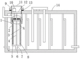
FIG. 1 is a schematic structural view of an integrated sewage treatment apparatus provided by the present invention;
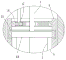
fig. 2 is an enlarged view of a structure at a in fig. 1.
In the figure: the device comprises a sleeve 1, a filter screen 2, a scraper 3, a support rod 4, a circular plate 5, a conical block 6, a positioning block 7, a filter pipe 8, a mounting pipe 9, a motor 10, a sealing plate 11, a cross rod 12, a limiting ring 13, a water tank 14, an annular sliding block 15, an annular sliding block 16, a gear 17 and a connecting rod 18.
Detailed Description
The technical solutions in the embodiments of the present invention will be described clearly and completely with reference to the accompanying drawings in the embodiments of the present invention, and it is obvious that the described embodiments are only some embodiments of the present invention, not all embodiments.
In the description of the present invention, it is to be understood that the terms "upper", "lower", "front", "rear", "left", "right", "top", "bottom", "inner", "outer", and the like indicate orientations or positional relationships based on the orientations or positional relationships shown in the drawings, and are only for convenience of description and simplicity of description, and do not indicate or imply that the device or element being referred to must have a particular orientation, be constructed and operated in a particular orientation, and therefore, should not be construed as limiting the present invention.
Referring to fig. 1-2, the integrated sewage treatment equipment comprises a water tank 14, a primary settling chamber, a contact oxidation chamber, a secondary settling chamber and a clear water disinfection chamber are sequentially arranged in the water tank 14 from left to right, a round hole is formed in the left side of the upper end of the water tank 14, an installation pipe 9 is slidably sleeved in the round hole, a limiting ring 13 is fixedly connected to the pipe wall of the installation pipe 9, a sleeve 1 is fixedly connected to the inner wall of the left side of the upper end of the water tank 14, a filter pipe 8 is slidably sleeved in the sleeve 1, the inner edge of the pipe orifice at the upper end of the filter pipe 8 is connected with the inner wall of the installation pipe 9 through a transmission mechanism, strip-shaped through holes are respectively formed in two opposite sides of the filter pipe 8, a filter screen 2 is fixedly connected to each of the two strip-shaped through holes, a water inlet pipe with an L-shaped structure is fixedly connected to, the bell jar has been seted up to the lower extreme of locating piece 7, lower extreme left side inner wall fixedly connected with toper piece 6 of water tank 14, the upper end and the bell jar sliding connection of toper piece 6, it is spacing to be convenient for filter tube 8 when the pairing rotation, dirty groove of collection has been seted up to the lower extreme left side inner wall slope of water tank 14, the left end downside fixedly connected with blow off pipe of water tank 14, the blow off pipe is connected with outside sludge pump, the lateral wall that the water tank 14 was passed to the one end of blow off pipe extends to the dirty inslot of collection, be convenient for discharge the interior slight granule rubbish of just sinking control chamber.
The transmission mechanism comprises a cross rod 12 fixed in the installation pipe 9, a support rod 4 is fixedly connected at the center of the lower end of the cross rod 12, the lower end of the support rod 4 penetrates through the sleeve 1 and extends into the filter pipe 8, a circular plate 5 is connected at the lower end pipe orifice of the filter pipe 8 in a contact manner, the upper end circle center of the circular plate 5 is rotatably connected with the lower end of the support rod 4 through a rolling bearing, an annular sliding groove is formed in the inner wall of the filter pipe 8, an annular sliding block 15 is connected in the annular sliding groove in a sliding manner, a connecting rod 18 is fixedly connected in the annular sliding block 15, the left side and the right side of the lower end of the connecting rod 18 are vertically and fixedly connected with scraping plates 3, the two scraping plates 3 are respectively connected with the inner walls of two opposite sides of the filter pipe 8 in a contact manner, so as to scrape garbage on, and when in use, under the gravity action of the filter pipe 8 and the garbage therein, the gear 17 is not easy to disengage from the inner gear ring 16 during transmission, the inner edge of the pipe orifice at the upper end of the filter pipe 8 is fixedly connected with the inner gear ring 16, the rod wall of the cross rod 12 is fixedly connected with the motor 10, the power input end of the motor 10 is electrically connected with an external power supply through a lead and a control switch, the technology is widely applied in life, and a person skilled in the art knows that redundant description is not needed, the output end of the motor 10 penetrates through the rod wall of the cross rod 12 and is fixedly connected with the gear 17, the gear 17 is meshed with the inner gear ring 16, the lower end of the spacing ring 13 is fixedly connected with a rubber ring, the rubber ring is in contact connection with the upper end of the water tank 14, the upper end of the spacing ring 13 is symmetrically and fixedly connected with two lifting lugs, which is convenient for taking out the garbage in the filter pipe 8 by, one side of the sealing plate 11, which is far away from the hinge, is fixedly connected with the pipe wall of the mounting pipe 9 through a lock catch, so that the amount of garbage accumulated in the filter pipe 8 can be checked conveniently.
In the utility model, sewage is input from the water inlet pipe, the sewage directly enters the filter pipe 8 and is filtered and discharged by the filter screen 2, the filtered solid garbage and suspended matters are stored in the filter pipe 8, so that the solid garbage and suspended matters entering the primary settling regulating reservoir can be effectively filtered, the treatment pressure of a subsequent sewage treatment functional area is reduced, the starting motor 10 drives the gear 17 to rotate the inner gear ring 16, the inner gear ring 16 rotates to drive the filter pipe 8 to rotate, the positioning block 7 and the conical block 6 can be matched to position the filter pipe 8 when the filter pipe 8 rotates, and the filter pipe 8 rotates to rub with the scraper 3, so that the treatment speed of treatment equipment can be effectively prevented from being influenced by the blockage of the filter screen 2, when the garbage needs to be cleaned, the lifting lug is lifted by using the lifting equipment, the lifting lug moves to drive the limiting ring 13 to move the installation pipe 9, the installation pipe 9 moves to drive the cross rod 12 to move the support rod, the bracing piece 4 removes and drives plectane 5 and remove to can remove filter tube 8 to 14 outsides of water tank fast, place plectane 5 on ground after removing 14 outsides of water tank, promote filter tube 8 along bracing piece 4 upwards slides and plectane 5 separation with the hand, thereby can arrange the rubbish in the filter tube 8 fast, be convenient for clear up the rubbish in the filtration equipment fast, reduced sewage treatment device's clearance cost.
The above, only be the concrete implementation of the preferred embodiment of the present invention, but the protection scope of the present invention is not limited thereto, and any person skilled in the art is in the technical scope of the present invention, according to the technical solution of the present invention and the utility model, the concept of which is equivalent to replace or change, should be covered within the protection scope of the present invention.
Claims (6)
1. Integrated sewage treatment equipment comprises a water tank (14), wherein a primary settling adjusting chamber, a contact oxidation chamber, a secondary settling chamber and a clear water disinfection chamber are sequentially arranged in the water tank (14) from left to right, and the integrated sewage treatment equipment is characterized in that a round hole is formed in the left side of the upper end of the water tank (14), an installation pipe (9) is sleeved in the round hole in a sliding manner, a limit ring (13) is fixedly connected onto the pipe wall of the installation pipe (9), a sleeve (1) is fixedly connected onto the inner wall of the left side of the upper end of the water tank (14), a filter pipe (8) is sleeved in the sleeve (1) in the sliding manner, the inner edge of the upper end pipe orifice of the filter pipe (8) is connected with the inner wall of the installation pipe (9) through a transmission mechanism, strip-shaped through holes are formed in two opposite sides of the filter pipe (8), a filter screen (2) is fixedly connected into the two strip-shaped through, one end of the horizontal part of the water inlet pipe is communicated with the pipe wall of the sleeve (1).
2. The integrated sewage treatment equipment according to claim 1, wherein the transmission mechanism comprises a cross rod (12) fixed in the installation pipe (9), a support rod (4) is fixedly connected to the center of the lower end of the cross rod (12), the lower end of the support rod (4) passes through the sleeve (1) and extends into the filter pipe (8), a circular plate (5) is connected to the lower end pipe orifice of the filter pipe (8) in a contact manner, the circle center of the upper end of the circular plate (5) is rotatably connected with the lower end of the support rod (4) through a rolling bearing, an annular sliding groove is formed in the inner wall of the filter pipe (8), an annular sliding block (15) is connected in the annular sliding groove in a sliding manner, a connecting rod (18) is fixedly connected in the annular sliding block (15), the connecting rod (18) is slidably sleeved with the rod wall of the support rod (4) through a through hole, and an inner gear ring (16) is fixedly connected in the, the motor (10) is fixedly connected to the rod wall of the cross rod (12), the output end of the motor (10) penetrates through the rod wall of the cross rod (12) and is fixedly connected with a gear (17), and the gear (17) is meshed with the inner gear ring (16).
3. The integrated sewage treatment equipment according to claim 2, wherein the left side and the right side of the lower end of the connecting rod (18) are vertically and fixedly connected with the scrapers (3), and the two scrapers (3) are respectively in contact connection with the inner walls of two opposite sides of the filter pipe (8).
4. The integrated sewage treatment device according to claim 2, wherein a positioning block (7) is fixedly connected to the center of the lower end of the circular plate (5), a conical groove is formed in the lower end of the positioning block (7), a conical block (6) is fixedly connected to the inner wall of the left side of the lower end of the water tank (14), and the upper end of the conical block (6) is slidably connected with the conical groove.
5. The integrated sewage treatment device according to claim 1, wherein a sewage collecting groove is obliquely formed in the inner wall of the left side of the lower end of the water tank (14), a sewage discharge pipe is fixedly connected to the lower side of the left end of the water tank (14), and one end of the sewage discharge pipe penetrates through the side wall of the water tank (14) and extends into the sewage collecting groove.
6. The integrated sewage treatment equipment according to claim 1, wherein a rubber ring is fixedly connected to the lower end of the limiting ring (13), the rubber ring is in contact connection with the upper end of the water tank (14), two lifting lugs are symmetrically and fixedly connected to the upper end of the limiting ring (13), a sealing plate (11) is hinged to the upper end pipe orifice of the mounting pipe (9) through a hinge, and one side, away from the hinge, of the sealing plate (11) is fixedly connected with the pipe wall of the mounting pipe (9) through a lock catch.
Priority Applications (1)
| Application Number | Priority Date | Filing Date | Title |
|---|---|---|---|
| CN201921239352.7U CN210481069U (en) | 2019-08-02 | 2019-08-02 | Integrated sewage treatment equipment |
Applications Claiming Priority (1)
| Application Number | Priority Date | Filing Date | Title |
|---|---|---|---|
| CN201921239352.7U CN210481069U (en) | 2019-08-02 | 2019-08-02 | Integrated sewage treatment equipment |
Publications (1)
| Publication Number | Publication Date |
|---|---|
| CN210481069U true CN210481069U (en) | 2020-05-08 |
Family
ID=70534003
Family Applications (1)
| Application Number | Title | Priority Date | Filing Date |
|---|---|---|---|
| CN201921239352.7U Active CN210481069U (en) | 2019-08-02 | 2019-08-02 | Integrated sewage treatment equipment |
Country Status (1)
| Country | Link |
|---|---|
| CN (1) | CN210481069U (en) |
Cited By (2)
| Publication number | Priority date | Publication date | Assignee | Title |
|---|---|---|---|---|
| CN114558382A (en) * | 2022-04-06 | 2022-05-31 | 上海清宁环境规划设计有限公司 | Online cleaning device for floaters, suspended matters and colloidal sludge in sewage discharge channel |
| CN116147013A (en) * | 2023-02-13 | 2023-05-23 | 北京慧峰仁和科技股份有限公司 | Circulating cooling water recovery device of steam turbine |
-
2019
- 2019-08-02 CN CN201921239352.7U patent/CN210481069U/en active Active
Cited By (3)
| Publication number | Priority date | Publication date | Assignee | Title |
|---|---|---|---|---|
| CN114558382A (en) * | 2022-04-06 | 2022-05-31 | 上海清宁环境规划设计有限公司 | Online cleaning device for floaters, suspended matters and colloidal sludge in sewage discharge channel |
| CN116147013A (en) * | 2023-02-13 | 2023-05-23 | 北京慧峰仁和科技股份有限公司 | Circulating cooling water recovery device of steam turbine |
| CN116147013B (en) * | 2023-02-13 | 2023-10-13 | 北京慧峰仁和科技股份有限公司 | Circulating cooling water recovery device of steam turbine |
Similar Documents
| Publication | Publication Date | Title |
|---|---|---|
| CN109847426A (en) | A kind of sewage treatment unit with collection waste residue function | |
| CN210481069U (en) | Integrated sewage treatment equipment | |
| CN210287092U (en) | Multi-medium filtering sewage treatment device capable of operating in stages | |
| CN108379909A (en) | A kind of sewage-treatment plant | |
| CN204079703U (en) | City river sewage disposal device | |
| CN217645972U (en) | Complete equipment suitable for sewage treatment of public toilets in scenic spots | |
| CN207551056U (en) | A kind of solid-liquid separating environmental sanitation dustbin | |
| CN208898640U (en) | A kind of small towns sewage treatment unit recycled | |
| CN212881420U (en) | Filter equipment for sewage treatment | |
| CN204343438U (en) | A kind of multi-functional sewage process well | |
| CN205294987U (en) | Novel waste water storage water tank | |
| CN208802951U (en) | A kind of wastewater treatment equipment | |
| CN204699482U (en) | A kind of sewage disposal filter | |
| CN216092467U (en) | Sewage treatment system with back flush function | |
| CN208485687U (en) | A kind of home-use sanitary sewage filter device | |
| CN207286831U (en) | A kind of sewage processing filtering device | |
| CN215559489U (en) | Sewage treatment purifier of municipal works construction | |
| CN205151950U (en) | City ditch sewage treatment plant | |
| CN205216391U (en) | Mobile sewage treatment device | |
| CN211411210U (en) | Pool water purification device convenient to clearance waste residue | |
| CN203977542U (en) | Floor drain | |
| CN208293714U (en) | A kind of municipal drainage system | |
| CN208694458U (en) | A kind of henhouse flushing chicken manure water purification installation | |
| CN220223900U (en) | Advanced treatment device | |
| CN205235574U (en) | Sewage treating pond |
Legal Events
| Date | Code | Title | Description |
|---|---|---|---|
| GR01 | Patent grant | ||
| GR01 | Patent grant |