CN210476207U - Clamping device for machining precision die - Google Patents
Clamping device for machining precision die Download PDFInfo
- Publication number
- CN210476207U CN210476207U CN201920766179.XU CN201920766179U CN210476207U CN 210476207 U CN210476207 U CN 210476207U CN 201920766179 U CN201920766179 U CN 201920766179U CN 210476207 U CN210476207 U CN 210476207U
- Authority
- CN
- China
- Prior art keywords
- fixedly connected
- clamping device
- accurate mould
- workbench
- box
- Prior art date
- Legal status (The legal status is an assumption and is not a legal conclusion. Google has not performed a legal analysis and makes no representation as to the accuracy of the status listed.)
- Expired - Fee Related
Links
Images

Landscapes
- Jigs For Machine Tools (AREA)
Abstract
The utility model discloses a clamping device is used in processing of accurate mould, comprises a workbench, the equal fixedly connected with supporting legs in four corners of workstation bottom, the platform is placed to the center fixedly connected with in department at workstation top, the rear side fixedly connected with curb plate at workstation top, the top fixedly connected with roof of curb plate, the bottom of roof is provided with drilling mechanism. The utility model discloses a set up installation mechanism, the box, the bearing, the threaded rod, the carousel, the handle, chucking mechanism, the screw thread piece, remove the post, prevent shaking mechanism, the cardboard, stopper and cushion and mutually support, reached and pressed from both sides tight effectual advantage to accurate mould, make accurate mould add man-hour, can effectually press from both sides tightly accurate mould, prevent that accurate mould from appearing sliding, prevent that accurate mould from appearing processing damage simultaneously, reduce the wastrel of accurate mould to accurate mould processing is with clamping device's practicality has been improved.
Description
Technical Field
The utility model relates to an accurate mould processing technology field specifically is a clamping device is used in accurate mould processing.
Background
The mould is used for making the tool of the shaping article, this kind of tool is formed by various parts, different moulds are formed by different parts, it mainly realizes the processing of the article appearance through the change of the physical state of the shaping material, it is the name of "industrial mother".
Precision mold adds man-hour, need use clamping device to in fixing precision mold, current precision mold processing presss from both sides tight effect not good with clamping device, leads to precision mold adding man-hour, appears sliding easily, causes precision mold to appear processing damage, makes precision mold's wastrel increase, thereby has reduced precision mold processing and has used clamping device's practicality.
SUMMERY OF THE UTILITY MODEL
Technical problem to be solved
The utility model provides a not enough to prior art, the utility model provides a clamping device is used in precision mold processing possesses the tight effectual advantage of clamp to precision mold, and it is not good to have solved current clamping device for precision mold processing and press from both sides tight effect, leads to precision mold to add man-hour, appears sliding easily, causes precision mold to appear processing the problem of damaging.
(II) technical scheme
In order to achieve the above object, the utility model provides a following technical scheme: a clamping device for machining a precise mold comprises a workbench, wherein supporting legs are fixedly connected to four corners of the bottom of the workbench, a placing table is fixedly connected to the center of the top of the workbench, a side plate is fixedly connected to the rear side of the top of the workbench, a top plate is fixedly connected to the top of the side plate, a drilling mechanism is arranged at the bottom of the top plate, mounting mechanisms are arranged on two sides of the top of the workbench, a box body is fixedly connected to the top of each mounting mechanism, a bearing is fixedly connected to one side of the inner wall of the box body, a threaded rod is sleeved in an inner cavity of the bearing, the outer end of the threaded rod penetrates through the outer side of the box body and is fixedly connected with a rotary table, a handle is fixedly connected to the bottom of the outer side of the rotary table, a clamping mechanism is arranged at the top of the outer side of the box, the anti-shaking mechanism is arranged on the outer side of the moving column, the inner side of the moving column penetrates through the outer portion of the box body and is fixedly connected with a clamping plate, limiting blocks are fixedly connected to four corners of the inner side of the clamping plate, and a cushion pad is fixedly connected to the center of the inner side of the clamping plate.
Preferably, the drilling mechanism includes the cylinder, the top of cylinder and the bottom fixed connection of roof, the left side fixedly connected with air pump of cylinder, the first servo motor of bottom fixedly connected with of cylinder, first servo motor's output fixedly connected with drill bit.
Preferably, installation mechanism includes the mounting panel, the top fixed connection of bolt and workstation is passed through to the bottom of mounting panel, the equal fixedly connected with installing support in four corners at mounting panel top, the top of installing support and the bottom fixed connection of box.
Preferably, the clamping mechanism includes the fixed block, the inboard top fixed connection in the box outside of fixed block, the draw-in groove has been seted up on the surface of carousel, there is the fixture block in the front of fixed block through activity round pin swing joint, the inner chamber to the draw-in groove is run through to the bottom of fixture block.
Preferably, the anti-shaking mechanism comprises a sliding sleeve, the inner side of the sliding sleeve is fixedly connected with the outer side of the movable column, the inner cavity of the sliding sleeve is slidably connected with a sliding rod, the two sides of the sliding rod are fixedly connected with connecting blocks, and the outer side of each connecting block is fixedly connected with the inner wall of the box body.
(III) advantageous effects
Compared with the prior art, the utility model provides a clamping device is used in accurate mould processing possesses following beneficial effect:
1. the utility model discloses a set up installation mechanism, the box, a bearing, the threaded rod, the carousel, a handle, chucking mechanism, the screw thread piece, remove the post, prevent shaking the mechanism, the cardboard, stopper and cushion mutually support, reached and tightly effectual advantage is pressed from both sides to accurate mould, it is not good to have solved current clamping device for precision mold machining and press from both sides tight effect, lead to accurate mould to add man-hour, slide appears easily, cause the problem that processing damage appears in accurate mould, make accurate mould add man-hour, can effectually press from both sides tight accurate mould, prevent that accurate mould from appearing sliding, prevent that processing damage from appearing in accurate mould simultaneously, reduce the wastrel of accurate mould, thereby the practicality of clamping device for precision mold machining has been improved.
2. The utility model solves the problem that the workbench slides when in use by arranging the supporting legs, increases the stability of the workbench when in use, has the function of convenient installation for the box body by arranging the installation mechanism, solves the problem that the box body is complicated when in installation, has the function of stabilizing the threaded rod when rotating by arranging the bearing, solves the problem that the threaded rod shakes when rotating, increases the stability of the threaded rod when rotating, has the function of clamping the turntable by arranging the clamping mechanism, solves the problem that the turntable autorotates after the rotation is finished, has the function of stabilizing the moving column when moving by arranging the anti-shaking mechanism, solves the problem that the moving column shakes when moving, increases the stability of the moving column when moving, and plays the role of protecting the precise mould by arranging the cushion pad, the problem of the cardboard when pressing from both sides tight precision mould, cause precision mould to appear pressing from both sides tight damage is solved.
Drawings
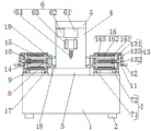
FIG. 1 is a schematic structural view of the present invention;
FIG. 2 is a left side view of the structure of the present invention;
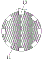
fig. 3 is a side view of the turntable of the present invention.
In the figure: 1 workbench, 2 supporting legs, 3 placing table, 4 side plates, 5 top plates, 6 drilling mechanism, 61 cylinder, 62 air pump, 63 first servo motor, 64 drill bit, 7 installation mechanism, 71 installation plate, 72 installation support, 8 box body, 9 bearing, 10 threaded rod, 11 turntable, 12 handle, 13 clamping mechanism, 131 fixing block, 132 clamping groove, 133 clamping block, 14 threaded block, 15 moving column, 16 anti-shaking mechanism, 161 sliding sleeve, 162 sliding rod, 163 connecting block, 17 clamping plate, 18 limiting block and 19 cushion pad.
Detailed Description
The technical solutions in the embodiments of the present invention will be described clearly and completely with reference to the accompanying drawings in the embodiments of the present invention, and it is obvious that the described embodiments are only some embodiments of the present invention, not all embodiments. Based on the embodiments in the present invention, all other embodiments obtained by a person skilled in the art without creative work belong to the protection scope of the present invention.
All the components of the present invention are general standard components or components known to those skilled in the art, and the structure and principle thereof can be known to those skilled in the art through technical manuals or through routine experimental methods.
Referring to fig. 1-3, a clamping device for precision mold processing comprises a workbench 1, wherein four corners of the bottom of the workbench 1 are fixedly connected with supporting legs 2, a placing table 3 is fixedly connected at the center of the top of the workbench 1, a side plate 4 is fixedly connected at the rear side of the top of the workbench 1, a top plate 5 is fixedly connected at the top of the side plate 4, a drilling mechanism 6 is arranged at the bottom of the top plate 5, mounting mechanisms 7 are arranged at two sides of the top of the workbench 1, a box body 8 is fixedly connected at the top of the mounting mechanisms 7, a bearing 9 is fixedly connected at one side of the inner wall of the box body 8, a threaded rod 10 is sleeved in an inner cavity of the bearing 9, the outer end of the threaded rod 10 penetrates through the outer side of the box body 8 and is fixedly connected with a turntable 11, a handle 12 is fixedly connected at the bottom of the outer side, the top and the bottom of the thread block 14 are fixedly connected with a movable column 15, the outer side of the movable column 15 is provided with an anti-shaking mechanism 16, the inner side of the movable column 15 penetrates through the outer part of the box body 8 and is fixedly connected with a clamping plate 17, the four corners of the inner side of the clamping plate 17 are fixedly connected with limiting blocks 18, the center of the inner side of the clamping plate 17 is fixedly connected with a cushion pad 19, the drilling mechanism 6 comprises a cylinder 61, the top of the cylinder 61 is fixedly connected with the bottom of the top plate 5, the left side of the cylinder 61 is fixedly connected with an air pump 62, the bottom of the cylinder 61 is fixedly connected with a first servo motor 63, the output end of the first servo motor 63 is fixedly connected with a drill bit 64, the mounting mechanism 7 comprises a mounting plate 71, the bottom of the mounting plate 71 is fixedly connected with the top of the workbench 1 through bolts, the four, the clamping mechanism 13 comprises a fixed block 131, the inner side of the fixed block 131 is fixedly connected with the top of the outer side of the box body 8, the surface of the rotary disc 11 is provided with a clamping groove 132, the front of the fixed block 131 is movably connected with a clamping block 133 through a movable pin, the bottom of the clamping block 133 penetrates into the inner cavity of the clamping groove 132, the anti-shaking mechanism 16 comprises a sliding sleeve 161, the inner side of the sliding sleeve 161 is fixedly connected with the outer side of the movable column 15, the inner cavity of the sliding sleeve 161 is slidably connected with a sliding rod 162, both sides of the sliding rod 162 are fixedly connected with connecting blocks 163, the outer side of the connecting blocks 163 is fixedly connected with the inner wall of the box body 8, the anti-skidding effect is achieved on the workbench 1 through the arrangement of the supporting legs 2, the problem that the workbench 1 slides in use is solved, the stability of the workbench 1 in use is improved, the installation, through setting up bearing 9, play stable effect when rotating to threaded rod 10, the problem that threaded rod 10 appears rocking when rotating has been solved, stability when threaded rod 10 rotates has been increased, through setting up chucking mechanism 13, play the effect of chucking to carousel 11, the problem that carousel 11 appears the rotation after the rotation is accomplished has been solved, through setting up anti-shake mechanism 16, play stable effect when moving to removal post 15, the problem that removes post 15 and appears rocking when removing has been solved, stability when removing post 15 and removing has been increased, through setting up blotter 19, play the effect of protection precision mould, the problem that precision mould appears pressing from both sides and damages when the cardboard 17 presss from both sides tight to precision mould has been solved, through setting up installation mechanism 7, box 8, bearing 9, threaded rod 10, carousel 11, handle 12, chucking mechanism 13, threaded block 14, Remove post 15, prevent shaking mechanism 16, cardboard 17, stopper 18 and cushion 19 mutually support, reached and tightly effectual advantage to accurate mould clamp, it is not good to have solved current accurate mould processing with clamping device clamp effect, it adds man-hour to lead to accurate mould, the easy slip that appears, cause accurate mould to appear processing the problem of damaging, make accurate mould add man-hour, can effectually press from both sides tight accurate mould, prevent that accurate mould from appearing slipping, prevent that accurate mould from appearing processing the damage simultaneously, reduce accurate mould's wastrel, thereby the practicality of precision mould processing with clamping device has been improved.
When the precise die is used, a worker firstly places the precise die to be drilled on the top of the placing table 3, then pulls the clamping block 133, so that the clamping block 133 leaves the inner cavity of the clamping groove 132 through the movable pin, then rotates the handle 12, the handle 12 rotates to drive the rotary table 11 to start rotating, the rotary table 11 rotates to drive the threaded rod 10 to start rotating in the inner cavity of the bearing 9, so that the threaded rod 10 rotates stably, meanwhile, the threaded rod 10 rotates to drive the threaded block 14 to start moving on the surface of the threaded rod 10 through threads, the threaded block 14 moves to drive the movable column 15 to start moving, the movable column 15 moves to drive the sliding sleeve 161 to slide on the surface of the sliding rod 162, so that the movable column 15 moves stably, meanwhile, the movable column 15 moves to push the clamping plate 17 to start moving, the clamping plate 17 moves to clamp the precise die, so that the precise die is prevented from, prevent that the precision mould from rocking before and after appearing, then stimulate fixture block 133 again, make fixture block 133 go into corresponding draw-in groove 132 inner chamber through the removable pin card, prevent that carousel 11 from appearing the rotation, then the workman is opening air pump 62 and first servo motor 63 through the peripheral hardware controller, first servo motor 63 starts to drive drill bit 64 and begins to rotate, then air pump 62 starts to carry high-pressure gas to the inner chamber of cylinder 61, the output pole of cylinder 61 promotes first servo motor 63 and drill bit 64 and begins to carry out drilling processing to the precision mould, make the precision mould add man-hour, can effectually press from both sides tight precision mould, prevent that the precision mould from appearing sliding, prevent that processing damage from appearing in the precision mould simultaneously, reduce the wastrel of precision mould, thereby reached and pressed from both sides tight effectual advantage to the precision mould.
The standard parts used in the present application document can be purchased from the market, and can be customized according to the description of the specification and the accompanying drawings, the specific connection mode of each part adopts the conventional means of mature bolt, rivet, welding and the like in the prior art, the machines, parts and equipment adopt the conventional models in the prior art, the circuit connection adopts the conventional connection mode in the prior art, no specific description is provided here, meanwhile, the electric elements appearing in the specification are all electrically connected with the external main controller and 220V mains supply, the peripheral controller mentioned in the specification can play a control role for the electric elements mentioned in the specification, and the peripheral controller is the conventional known equipment.
To sum up, this clamping device for precision mold processing mutually supports through installation mechanism 7, box 8, bearing 9, threaded rod 10, carousel 11, handle 12, chucking mechanism 13, screw block 14, removal post 15, anti-shake mechanism 16, cardboard 17, stopper 18 and cushion 19, has solved current clamping device for precision mold processing and has pressed from both sides tight effect not good, leads to precision mold to add man-hour, appears sliding easily, causes precision mold to appear processing damage's problem.
Although embodiments of the present invention have been shown and described, it will be appreciated by those skilled in the art that changes, modifications, substitutions and alterations can be made in these embodiments without departing from the principles and spirit of the invention, the scope of which is defined in the appended claims and their equivalents.
Claims (5)
1. The utility model provides a clamping device is used in precision mold processing, includes workstation (1), its characterized in that: the four corners of the bottom of the workbench (1) are fixedly connected with supporting legs (2), the center of the top of the workbench (1) is fixedly connected with a placing table (3), the rear side of the top of the workbench (1) is fixedly connected with a side plate (4), the top of the side plate (4) is fixedly connected with a top plate (5), the bottom of the top plate (5) is provided with a drilling mechanism (6), two sides of the top of the workbench (1) are respectively provided with an installing mechanism (7), the top of the installing mechanism (7) is fixedly connected with a box body (8), one side of the inner wall of the box body (8) is fixedly connected with a bearing (9), an inner cavity of the bearing (9) is sleeved with a threaded rod (10), the outer end of the threaded rod (10) penetrates through the outer side of the box body (8) and is fixedly connected with a turntable (11), the bottom of the outer, the top in the box (8) outside is provided with chucking mechanism (13), the surperficial threaded connection of threaded rod (10) has screw block (14), the equal fixedly connected with in top and the bottom of screw block (14) removes post (15), the outside of removing post (15) is provided with prevents shaking mechanism (16), the inboard of removing post (15) runs through to the outside and the fixedly connected with cardboard (17) of box (8), the equal fixedly connected with stopper (18) in four corners of cardboard (17) inboard, fixedly connected with blotter (19) are located to the inboard center of cardboard (17).
2. The clamping device for precision mold machining according to claim 1, characterized in that: drilling mechanism (6) include cylinder (61), the top of cylinder (61) and the bottom fixed connection of roof (5), the left side fixedly connected with air pump (62) of cylinder (61), the first servo motor (63) of bottom fixedly connected with of cylinder (61), the output fixedly connected with drill bit (64) of first servo motor (63).
3. The clamping device for precision mold machining according to claim 1, characterized in that: installation mechanism (7) include mounting panel (71), the top fixed connection of bolt and workstation (1) is passed through to the bottom of mounting panel (71), the equal fixedly connected with installing support (72) in four corners at mounting panel (71) top, the top of installing support (72) and the bottom fixed connection of box (8).
4. The clamping device for precision mold machining according to claim 1, characterized in that: chucking mechanism (13) include fixed block (131), the top fixed connection in the inboard and box (8) outside of fixed block (131), draw-in groove (132) have been seted up on the surface of carousel (11), there is fixture block (133) front of fixed block (131) through removable pin swing joint, the inner chamber to draw-in groove (132) is run through to the bottom of fixture block (133).
5. The clamping device for precision mold machining according to claim 1, characterized in that: the anti-shaking mechanism (16) comprises a sliding sleeve (161), the inner side of the sliding sleeve (161) is fixedly connected with the outer side of the moving column (15), a sliding rod (162) is connected to the inner cavity of the sliding sleeve (161) in a sliding mode, connecting blocks (163) are fixedly connected to the two sides of the sliding rod (162), and the outer side of each connecting block (163) is fixedly connected with the inner wall of the box body (8).
Priority Applications (1)
| Application Number | Priority Date | Filing Date | Title |
|---|---|---|---|
| CN201920766179.XU CN210476207U (en) | 2019-05-27 | 2019-05-27 | Clamping device for machining precision die |
Applications Claiming Priority (1)
| Application Number | Priority Date | Filing Date | Title |
|---|---|---|---|
| CN201920766179.XU CN210476207U (en) | 2019-05-27 | 2019-05-27 | Clamping device for machining precision die |
Publications (1)
| Publication Number | Publication Date |
|---|---|
| CN210476207U true CN210476207U (en) | 2020-05-08 |
Family
ID=70512178
Family Applications (1)
| Application Number | Title | Priority Date | Filing Date |
|---|---|---|---|
| CN201920766179.XU Expired - Fee Related CN210476207U (en) | 2019-05-27 | 2019-05-27 | Clamping device for machining precision die |
Country Status (1)
| Country | Link |
|---|---|
| CN (1) | CN210476207U (en) |
Cited By (1)
| Publication number | Priority date | Publication date | Assignee | Title |
|---|---|---|---|---|
| CN113681055A (en) * | 2021-10-27 | 2021-11-23 | 徐州市通泰交通设施有限公司 | Device and method for processing highway traffic guardrail |
-
2019
- 2019-05-27 CN CN201920766179.XU patent/CN210476207U/en not_active Expired - Fee Related
Cited By (1)
| Publication number | Priority date | Publication date | Assignee | Title |
|---|---|---|---|---|
| CN113681055A (en) * | 2021-10-27 | 2021-11-23 | 徐州市通泰交通设施有限公司 | Device and method for processing highway traffic guardrail |
Similar Documents
| Publication | Publication Date | Title |
|---|---|---|
| CN206732949U (en) | A kind of novel mechanical manufactures workbench | |
| CN210476207U (en) | Clamping device for machining precision die | |
| CN215968155U (en) | Polishing equipment for long shaft machining | |
| CN211389877U (en) | Positioning mechanism for injection mold of automobile lamp bottom shell | |
| CN211441493U (en) | Rigging machine suitable for not unidimensional material | |
| CN210677169U (en) | Fixed stable cutting device for special-shaped workpiece | |
| CN218192021U (en) | Fitment is built with five metals work piece piercing press that possesses upset function in room | |
| CN207788342U (en) | A kind of processing precise copper casting drilling and milling machine | |
| CN211465982U (en) | Fastener is polished and is used clamping device | |
| CN215092151U (en) | Frock clamp of auto-parts processing usefulness | |
| CN213497803U (en) | Automatic clamp | |
| CN209986618U (en) | Numerical control vertical milling machine presss from both sides with getting device convenient to adjust | |
| CN211414395U (en) | Anti-deviation device for bearing ring machining | |
| CN210282014U (en) | Clamping device is used in car shell processing | |
| CN211111716U (en) | Cutting machine for glass processing | |
| CN211361964U (en) | Anchor clamps for machining convenient to adjust | |
| CN216575212U (en) | Novel mould location frock | |
| CN112372536A (en) | Clamp convenient for positioning for automobile part machining and operation method | |
| CN213259064U (en) | Clamping jig for automobile inspection tool | |
| CN216138504U (en) | Clamp of machine tool | |
| CN213411768U (en) | Novel shaft sleeve and base processing jig | |
| CN210476301U (en) | Moving frame for machine tool machining | |
| CN220970764U (en) | Lathe equipment for mold processing | |
| CN219787847U (en) | Automatic equipment of polishing of high strength mould spare and accessory parts | |
| CN218136622U (en) | Composite machine tool |
Legal Events
| Date | Code | Title | Description |
|---|---|---|---|
| GR01 | Patent grant | ||
| GR01 | Patent grant | ||
| CF01 | Termination of patent right due to non-payment of annual fee | ||
| CF01 | Termination of patent right due to non-payment of annual fee |
Granted publication date: 20200508 Termination date: 20210527 |