CN210473212U - Device for improving self-circulation of sewage treatment plant - Google Patents
Device for improving self-circulation of sewage treatment plant Download PDFInfo
- Publication number
- CN210473212U CN210473212U CN201920883045.6U CN201920883045U CN210473212U CN 210473212 U CN210473212 U CN 210473212U CN 201920883045 U CN201920883045 U CN 201920883045U CN 210473212 U CN210473212 U CN 210473212U
- Authority
- CN
- China
- Prior art keywords
- fixedly connected
- frame
- connecting rod
- filter screen
- sewage treatment
- Prior art date
- Legal status (The legal status is an assumption and is not a legal conclusion. Google has not performed a legal analysis and makes no representation as to the accuracy of the status listed.)
- Expired - Fee Related
Links
Images

Landscapes
- Filtration Of Liquid (AREA)
Abstract
The utility model discloses an improve device of sewage treatment plant self-loopa, which comprises a frame, the top internal surface fixedly connected with rose box of frame, the inside fixedly connected with filter screen of rose box, the last fixed surface of filter screen is connected with the fixed block, two the mounting groove has not been seted up, two is equallyd divide to the both sides outer wall of fixed block other fixedly connected with first pneumatic cylinder, two is equallyd divide to one side outer wall in opposite directions of mounting groove one side outer wall that first pneumatic cylinder is relative does not be equipped with first hydraulic stem, the one end fixedly connected with sleeve of first pneumatic cylinder is kept away from to first hydraulic stem, telescopic inside sliding connection has first connecting rod, the top fixedly connected with limiting plate of first connecting rod. The utility model relates to a simply, convenient operation can clear up the granule on the filter screen, can not make the filter screen blockked up to can also remove the receipts workbin, conveniently handle the granule of receiving the workbin.
Description
Technical Field
The utility model relates to a sewage treatment device technical field especially relates to an improve sewage treatment plant self-loopa's device.
Background
The sewage treatment plant is sewage discharged from a pollution source, and the total amount or concentration of the pollutant is higher, so that the sewage cannot meet the requirement of a discharge standard or the requirement of environmental capacity, so that when the water environment quality and the function target are reduced, places needing artificial strengthening treatment are generally divided into a municipal concentrated sewage treatment plant and various pollution source dispersed sewage treatment plants, the sewage is discharged into a water body or a municipal pipeline after treatment, and sometimes, in order to recycle the wastewater resource, the sewage treatment plant needs to be constructed for recycling or recycling when the quality of treated effluent water needs to be improved.
Especially, the filtering link in the self-circulation device of the sewage treatment plant is particularly important, if the bad filtering effect on the particles in the sewage can influence the operation of the whole circulation device, the filtering equipment in the sewage treatment plant can not treat the particles on the filtering net, so that the filtering net can not block the particles in the water.
SUMMERY OF THE UTILITY MODEL
The utility model aims at solving the defects existing in the prior art and providing a device for improving self circulation of a sewage treatment plant.
In order to achieve the above purpose, the utility model adopts the following technical scheme:
a device for improving self-circulation of a sewage treatment plant comprises a frame, wherein a filter box is fixedly connected to the inner surface of the top of the frame, a filter screen is fixedly connected to the inside of the filter box, fixed blocks are fixedly connected to the upper surface of the filter screen, mounting grooves are respectively formed in the outer walls of two sides of the two fixed blocks, the outer wall of one opposite side of the two mounting grooves is respectively and fixedly connected with a first hydraulic cylinder, a first hydraulic rod is respectively arranged on the outer wall of one opposite side of the two first hydraulic cylinders, a sleeve is fixedly connected to one end, away from the first hydraulic cylinder, of the first hydraulic rod, a first connecting rod is slidably connected to the inside of the sleeve, a limiting plate is fixedly connected to the top end of the first connecting rod, a second connecting rod is slidably sleeved on the inner wall of the first connecting rod, a push plate is fixedly connected to the, the spring is sleeved with the first connecting rod and the second connecting rod in a sliding manner, through holes are formed in the outer walls of the two sides of the filter box, grooves are formed in the lower surfaces of the through holes, rectangular cavities are formed in the upper surfaces of the through holes, pull plates are sleeved in the rectangular cavities in a sliding manner, baffle plates are fixedly connected to the lower surfaces of the pull plates, discs are fixedly connected to the upper surfaces of the pull plates and are located on the upper surface of the frame, pull rings are fixedly connected to the upper surfaces of the discs, inclined plates are fixedly connected to the inner surface of the bottom of the filter box in a symmetrical manner, second hydraulic cylinders are fixedly connected to the inner surface of the bottom of the frame in a symmetrical manner, second hydraulic cylinders are respectively arranged on the upper surfaces of the two second hydraulic cylinders, mounting plates are respectively and fixedly connected to the top ends of the two second hydraulic cylinders, material receiving boxes are fixedly connected to the upper surfaces, the material receiving box is respectively connected with the frame and the filter box in a sliding manner.
Preferably, the fixed block is positioned on the inner surface of the bottom of the frame, and the fixed block is fixedly connected with the frame.
Preferably, the limiting plate is located above the sleeve, the push plate is located on the upper surface of the filter screen, and the push plate is connected with the filter screen in a sliding mode.
Preferably, the baffle is located inside the through hole, the baffle is connected with the through hole in a sliding mode, the bottom end of the baffle is located inside the groove, and the baffle is connected with the groove in a sliding mode.
Preferably, the bottom fixedly connected with connecting pipe of rose box, the bottom fixedly connected with water storage box of connecting pipe, the water storage box is located the bottom internal surface of frame, fixed connection between water storage box and the frame, the outer wall fixedly connected with outlet pipe of one side of water storage box.
Preferably, the upper surface of the frame is symmetrically and fixedly connected with a water inlet pipe, and the water inlet pipe is communicated with the filter box.
Compared with the prior art, the beneficial effects of the utility model are that:
1. in the utility model, the spring is arranged, so that the push plate can be tightly pressed on the filter screen, and the particles on the filter screen are quickly cleaned;
2. in the utility model, the second hydraulic cylinder and the second hydraulic rod are arranged, so that the material receiving box can be moved down, and the particles in the material receiving box can be conveniently treated by people;
to sum up, the utility model relates to a simply, convenient operation can clear up the granule on the filter screen, can not make the filter screen blockked up to can also remove the receipts workbin and get off, conveniently handle the granule of receiving the workbin.
Drawings
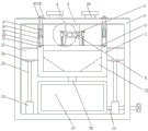
Fig. 1 is a schematic structural diagram of a device for improving self-circulation of a sewage treatment plant according to the present invention;
fig. 2 is an enlarged view of a structure at a position a of the device for improving self-circulation of the sewage treatment plant.
In the figure: the filter comprises a frame 1, a filter box 2, a filter screen 3, a fixing block 4, a mounting groove 5, a first hydraulic cylinder 6, a first hydraulic rod 7, a sleeve 8, a first connecting rod 9, a limiting plate 10, a second connecting rod 11, a push plate 12, a spring 13, a through hole 14, a groove 15, a rectangular cavity 16, a pull plate 17, a baffle 18, a disc 19, a pull-out plate 20, a sloping plate 21, a second hydraulic cylinder 22, a second hydraulic rod 23, a mounting plate 24, a material receiving box 25, a connecting pipe 26, a water storage box 27, a water outlet pipe 28 and a water inlet pipe 29.
Detailed Description
The technical solutions in the embodiments of the present invention will be described clearly and completely with reference to the accompanying drawings in the embodiments of the present invention, and it is obvious that the described embodiments are only some embodiments of the present invention, not all embodiments.
Referring to fig. 1-2, a device for improving self-circulation of a sewage treatment plant comprises a frame 1, a filter box 2 is fixedly connected to the inner surface of the top of the frame 1, a filter screen 3 is fixedly connected to the inside of the filter box 2, fixed blocks 4 are fixedly connected to the upper surface of the filter screen 3, mounting grooves 5 are respectively formed on the outer walls of two sides of the two fixed blocks 4, a first hydraulic cylinder 6 is respectively fixedly connected to the outer wall of one side of the two mounting grooves 5 opposite to each other, a first hydraulic rod 7 is respectively arranged on the outer wall of one side of the two first hydraulic cylinders 6 opposite to each other, a sleeve 8 is fixedly connected to one end of the first hydraulic rod 7 far away from the first hydraulic cylinder 6, a first connecting rod 9 is slidably connected to the inside of the sleeve 8, a limiting plate 10 is fixedly connected to the top end of the first connecting rod 9, a second connecting rod, a spring 13 is fixedly connected between the sleeve 8 and the push plate 12, the spring 13 is slidably sleeved with the first connecting rod 9 and the second connecting rod 11, through holes 14 are respectively formed in the outer walls of the two sides of the filter box 2, grooves 15 are formed in the lower surfaces of the through holes 14, rectangular cavities 16 are formed in the upper surfaces of the through holes 14, pull plates 17 are slidably sleeved in the rectangular cavities 16, baffles 18 are fixedly connected to the lower surfaces of the pull plates 17, discs 19 are fixedly connected to the upper surfaces of the pull plates 17, the discs 19 are located on the upper surface of the frame 1, pull rings 20 are fixedly connected to the upper surfaces of the discs 19, inclined plates 21 are symmetrically and fixedly connected to the inner surface of the bottom of the filter box 2, second hydraulic cylinders 22 are symmetrically and fixedly connected to the inner surface of the bottom of the frame 1, second hydraulic cylinders 23 are respectively arranged on the upper surfaces of the two second hydraulic cylinders 22, mounting plates 24 are respectively and fixedly connected to the, the material receiving box 25 is positioned between the frame 1 and the filter box 2, and the material receiving box 25 is respectively connected with the frame 1 and the filter box 2 in a sliding way.
Fixed block 4 is located the bottom internal surface of frame 1, fixed connection between fixed block 4 and the frame 1, limiting plate 10 is located sleeve 8's top, push pedal 12 is located the upper surface of filter screen 3, sliding connection between push pedal 12 and the filter screen 3, baffle 18 is located the inside of through-hole 14, sliding connection between baffle 18 and the through-hole 14, the bottom of baffle 18 is located the inside of recess 15, sliding connection between baffle 18 and the recess 15, the bottom fixedly connected with connecting pipe 26 of rose box 2, the bottom fixedly connected with water storage box 27 of connecting pipe 26, water storage box 27 is located the bottom internal surface of frame 1, fixed connection between water storage box 27 and the frame 1, one side outer wall fixedly connected with outlet pipe 28 of water storage box 27, the upper surface symmetry fixedly connected with inlet tube 29 of frame 1, be linked together between inlet tube 29 and the rose box 2.
The working principle is as follows: when the utility model is used, sewage is input into the filter box 2 from the water inlet pipe 29, the filter screen 3 in the filter box 2 filters particles in the sewage, so that the particles are left on the filter screen 3, when the sewage is filtered, the sewage flows into the water storage box 27 from the filter box 2 through the connecting pipe 26, two inclined plates 21 in the filter box 2 can ensure that the sewage flows out and is cleaned, then a pulling damage 20 on the disc 19 is pulled, the pulling damage 20 drives the pulling plate 17 to move, the pulling plate 17 drives the baffle 18 to move, so that the baffle 18 is separated from the through hole 14, the through hole 14 is opened, at the moment, a switch of the first hydraulic cylinder 6 is started, the first hydraulic cylinder 6 pushes the first hydraulic rod 7 to move, the first hydraulic rod 7 pushes the sleeve 8 to move, the sleeve 8 drives the first connecting rod 9 and the push plate 12 under the second connecting rod 11 to move on the filter screen 3, the push plate 12 can push the particles on the filter screen 3 to the through hole, and under the action of the spring 13 between the sleeve 8 and the push plate 12, the push plate 12 can be tightly pressed on the filter screen 3, so that particles on the filter screen 3 are quickly cleaned; the push plate 12 pushes the particles to the through hole 14, the particles fall into the material receiving box 25, then the switch of the second hydraulic cylinder 22 is started, the second hydraulic cylinder 22 pulls the second hydraulic rod 23 to move downwards, the second hydraulic rod 23 pulls the material receiving box 25 on the mounting plate 24 to move downwards, so that the material receiving box 25 can move downwards, and people can conveniently process the particles in the material receiving box 25; the utility model relates to a simply, convenient operation can clear up the granule on the filter screen 3, can not make the filter screen blockked up to can also remove the receipts workbin 25 and get off, the convenient granule to receiving the workbin 25 is handled.
The above, only be the concrete implementation of the preferred embodiment of the present invention, but the protection scope of the present invention is not limited thereto, and any person skilled in the art is in the technical scope of the present invention, according to the technical solution of the present invention and the utility model, the concept of which is equivalent to replace or change, should be covered within the protection scope of the present invention.
Claims (6)
1. The device for improving the self-circulation of the sewage treatment plant comprises a frame (1) and is characterized in that a filter box (2) is fixedly connected to the inner surface of the top of the frame (1), a filter screen (3) is fixedly connected to the inside of the filter box (2), fixed blocks (4) are fixedly connected to the upper surface of the filter screen (3), mounting grooves (5) are respectively formed in the outer walls of the two sides of the two fixed blocks (4), a first hydraulic cylinder (6) is respectively and fixedly connected to the outer wall of one opposite side of the two mounting grooves (5), a first hydraulic rod (7) is respectively and fixedly arranged on the outer wall of one opposite side of the two first hydraulic cylinders (6), a sleeve (8) is fixedly connected to one end, far away from the first hydraulic cylinder (6), of the first hydraulic rod (7), a first connecting rod (9) is fixedly connected to the inside of, the top end of the first connecting rod (9) is fixedly connected with a limiting plate (10), the inner wall of the first connecting rod (9) is slidably sleeved with a second connecting rod (11), the bottom end of the second connecting rod (11) is fixedly connected with a push plate (12), a spring (13) is fixedly connected between the sleeve (8) and the push plate (12), the spring (13) is slidably sleeved between the first connecting rod (9) and the second connecting rod (11), through holes (14) are formed in the outer walls of the two sides of the filter box (2), grooves (15) are formed in the lower surfaces of the through holes (14), rectangular cavities (16) are formed in the upper surfaces of the through holes (14), pull plates (17) are slidably sleeved in the rectangular cavities (16), baffle plates (18) are fixedly connected to the lower surfaces of the pull plates (17), and discs (19) are fixedly connected to the upper surfaces of the pull plates (17), disc (19) are located the upper surface of frame (1), the last fixed surface of disc (19) is connected with pull ring (20), the bottom internal surface symmetry fixedly connected with swash plate (21) of rose box (2), the bottom internal surface symmetry fixedly connected with second hydraulic cylinder (22) of frame (1), two the upper surface of second hydraulic cylinder (22) is equallyd divide and is do not equipped with second hydraulic cylinder (23), two do not fixedly connected with mounting panel (24) are equallyd divide on the top of second hydraulic cylinder (23), the last fixed surface of mounting panel (24) is connected with receipts workbin (25), it is located between frame (1) and rose box (2) to receive workbin (25), receive workbin (25) equally divide do not with sliding connection between frame (1) and the rose box (2).
2. The apparatus for improving self-circulation of a sewage treatment plant according to claim 1, wherein the fixing block (4) is located on the bottom inner surface of the frame (1), and the fixing block (4) is fixedly connected with the frame (1).
3. The device for improving self-circulation of a sewage treatment plant according to claim 1, wherein the limiting plate (10) is located above the sleeve (8), the push plate (12) is located on the upper surface of the filter screen (3), and the push plate (12) is connected with the filter screen (3) in a sliding manner.
4. The device for improving self-circulation of the sewage treatment plant according to claim 1, wherein the baffle (18) is located inside the through hole (14), the baffle (18) is slidably connected with the through hole (14), the bottom end of the baffle (18) is located inside the groove (15), and the baffle (18) is slidably connected with the groove (15).
5. The device for improving the self-circulation of the sewage treatment plant according to claim 1, wherein a connecting pipe (26) is fixedly connected to the bottom end of the filter tank (2), a water storage tank (27) is fixedly connected to the bottom end of the connecting pipe (26), the water storage tank (27) is positioned on the inner surface of the bottom of the frame (1), the water storage tank (27) is fixedly connected with the frame (1), and an outlet pipe (28) is fixedly connected to the outer wall of one side of the water storage tank (27).
6. The device for improving the self-circulation of the sewage treatment plant according to the claim 1 is characterized in that the upper surface of the frame (1) is symmetrically and fixedly connected with a water inlet pipe (29), and the water inlet pipe (29) is communicated with the filter box (2).
Priority Applications (1)
| Application Number | Priority Date | Filing Date | Title |
|---|---|---|---|
| CN201920883045.6U CN210473212U (en) | 2019-06-13 | 2019-06-13 | Device for improving self-circulation of sewage treatment plant |
Applications Claiming Priority (1)
| Application Number | Priority Date | Filing Date | Title |
|---|---|---|---|
| CN201920883045.6U CN210473212U (en) | 2019-06-13 | 2019-06-13 | Device for improving self-circulation of sewage treatment plant |
Publications (1)
| Publication Number | Publication Date |
|---|---|
| CN210473212U true CN210473212U (en) | 2020-05-08 |
Family
ID=70513607
Family Applications (1)
| Application Number | Title | Priority Date | Filing Date |
|---|---|---|---|
| CN201920883045.6U Expired - Fee Related CN210473212U (en) | 2019-06-13 | 2019-06-13 | Device for improving self-circulation of sewage treatment plant |
Country Status (1)
| Country | Link |
|---|---|
| CN (1) | CN210473212U (en) |
-
2019
- 2019-06-13 CN CN201920883045.6U patent/CN210473212U/en not_active Expired - Fee Related
Similar Documents
| Publication | Publication Date | Title |
|---|---|---|
| CN209651999U (en) | A kind of multi-stage sewage filter device | |
| CN208234735U (en) | A kind of sludge high effective dehydration device | |
| CN209068517U (en) | A kind of refuse incinerator slag sewage sludge separating and treating apparatus | |
| CN206304418U (en) | A kind of energy-saving sewage treating device | |
| CN209974434U (en) | Automatic filtering device | |
| CN210473212U (en) | Device for improving self-circulation of sewage treatment plant | |
| CN207581524U (en) | A kind of sewage purification circulation uses environmental protecting device | |
| CN208161123U (en) | A kind of hydraulic engineering filter device | |
| CN216999608U (en) | Water surface blue algae collector and system comprising same | |
| CN109821285B (en) | Domestic sewage filters utilizes system | |
| CN204747450U (en) | Remover recovery unit | |
| CN206204050U (en) | A kind of water treatment facilities for sanitary sewage drainage arrangement | |
| CN211111304U (en) | Artificial wetland for sewage treatment and ecological restoration | |
| CN211056942U (en) | Sludge press filtration device for sewage treatment | |
| CN205007734U (en) | Sesame oil filtration equipment | |
| CN210237282U (en) | Water source filter equipment is used in production of diesel vehicle tail gas treatment liquid | |
| CN213771530U (en) | Active burnt adsorption equipment of sewage treatment fluidized bed granule | |
| CN219585009U (en) | Urban intelligent garbage management device | |
| CN214936467U (en) | Filter equipment for sewage treatment | |
| CN214088090U (en) | Multistage waste water treatment pond | |
| CN216073276U (en) | Sewage treatment plant that building engineering construction used | |
| CN215939219U (en) | Preliminary screening device for sewage treatment | |
| CN204151208U (en) | A kind of dry slag disposal oil removal all-in-one | |
| CN216395424U (en) | Concrete is pressure filter for sewage | |
| CN213885145U (en) | Wastewater treatment device for aniline production |
Legal Events
| Date | Code | Title | Description |
|---|---|---|---|
| GR01 | Patent grant | ||
| GR01 | Patent grant | ||
| CF01 | Termination of patent right due to non-payment of annual fee |
Granted publication date: 20200508 Termination date: 20210613 |
|
| CF01 | Termination of patent right due to non-payment of annual fee |