CN210467917U - Power battery system of electric automobile - Google Patents
Power battery system of electric automobile Download PDFInfo
- Publication number
- CN210467917U CN210467917U CN201921461463.2U CN201921461463U CN210467917U CN 210467917 U CN210467917 U CN 210467917U CN 201921461463 U CN201921461463 U CN 201921461463U CN 210467917 U CN210467917 U CN 210467917U
- Authority
- CN
- China
- Prior art keywords
- battery
- box body
- bus bar
- positive
- negative
- Prior art date
- Legal status (The legal status is an assumption and is not a legal conclusion. Google has not performed a legal analysis and makes no representation as to the accuracy of the status listed.)
- Active
Links
Images
Classifications
-
- Y—GENERAL TAGGING OF NEW TECHNOLOGICAL DEVELOPMENTS; GENERAL TAGGING OF CROSS-SECTIONAL TECHNOLOGIES SPANNING OVER SEVERAL SECTIONS OF THE IPC; TECHNICAL SUBJECTS COVERED BY FORMER USPC CROSS-REFERENCE ART COLLECTIONS [XRACs] AND DIGESTS
- Y02—TECHNOLOGIES OR APPLICATIONS FOR MITIGATION OR ADAPTATION AGAINST CLIMATE CHANGE
- Y02E—REDUCTION OF GREENHOUSE GAS [GHG] EMISSIONS, RELATED TO ENERGY GENERATION, TRANSMISSION OR DISTRIBUTION
- Y02E60/00—Enabling technologies; Technologies with a potential or indirect contribution to GHG emissions mitigation
- Y02E60/10—Energy storage using batteries
Abstract
The utility model relates to the field of new energy automobiles, in particular to an electric automobile power battery system; the battery box comprises a box body, wherein a box cover which is connected in a sealing way is covered on the box body, a positive connecting terminal, a negative connecting terminal and a communication aerial connector are arranged outside the box body, and at least one battery module, a high-voltage control system and a battery system control module are arranged in the box body; by the technical scheme, the size of the space in the box body is small, the box body has the characteristics of standardization and universalization, and the space of different areas of the whole vehicle is fully utilized for electric energy arrangement; the battery in the box body can adopt a modularized form or a modularized form according to actual conditions, the installation is simple and convenient, the processing and manufacturing cost is low, high-voltage and low-voltage are divided into two paths to be executed, the electromagnetic interference can be effectively avoided, and a high-voltage control system is arranged, so that the whole device is compact in structure, concise in layout and high in production efficiency.
Description
Technical Field
The utility model relates to a new energy automobile field, concretely relates to electric automobile power battery system.
Background
With the development of science and technology and the progress of society, due to the increasing exhaustion of petroleum resources and the pressure of environmental protection, new energy automobiles become the key point of research and development of the future automobile industry, the industry recognizes that the most key component of new energy electric automobiles is a power battery system assembly at present, the most common power battery of pure electric automobiles at the present stage is a secondary lithium battery, and a plurality of single lithium batteries are combined in different series or parallel or series-parallel combination modes to provide the voltage and the electric quantity required by the electric automobiles. Sometimes, a larger battery system is formed by combining a plurality of different sub-power battery systems in series and parallel again to provide power for the electric automobile; especially in the express delivery industry, the urban logistics transportation cost pressure is increased sharply. In order to solve the last kilometer of urban transportation, the demand of industries and governments on pure electric low-speed logistics vehicles is increasing day by day. In the prior art, all power battery systems of a pure electric low-speed logistics vehicle use a lead-acid battery scheme, and the biggest defect of the method is serious pollution to the environment. Therefore, for a pure electric logistics vehicle, a corresponding power battery system needs to be developed by considering the actual use condition of the vehicle, and if the logistics vehicle requires low operation cost, the vehicle does not need to travel for a long distance in urban operation, and the vehicle runs frequently, namely needs frequent quick charging and also needs long-time full charging.
SUMMERY OF THE UTILITY MODEL
To the problem mentioned in the prior art, the utility model aims at providing an electric automobile power battery system.
The utility model relates to an electric automobile power battery system, including the box, the box upper cover closes a sealed case lid that links to each other, states the box and is equipped with positive connecting terminal, negative connecting terminal and communication boat and inserts outward, is equipped with at least one battery module, high-pressure control system and battery system control module in the box, the battery module links to each other with battery system control module, high-pressure control system respectively, and battery system control module links to each other with high-pressure control system, high-pressure control system links to each other with positive connecting terminal and negative connecting terminal located outside the box respectively;
the battery module comprises a plurality of battery modules connected in series, a protective cover, an insulating plate, serial busbars, end busbars, mounting supports and screws, the serial busbars are arranged between the adjacent battery modules connected in series, the two ends of the outermost side of each battery module are respectively provided with the end busbars, the insulating plates and the mounting supports from inside to outside in sequence, the screws penetrate through the end mounting supports, the insulating plates, the end busbars and the battery modules in sequence and penetrate out of the mounting supports at the other ends of the battery modules, the battery modules are connected in series into a whole, and the protective cover is arranged at the top of each battery module.
Preferably, the high-voltage control system comprises an electric control relay, a pre-charging resistor, a pre-charging relay, a shunt, a positive connecting wire and a negative connecting wire, wherein the electric control relay is respectively connected with the pre-charging resistor, the pre-charging relay and the shunt, one end of the positive connecting wire is connected with the electric control relay, the other end of the positive connecting wire is connected with the positive pole of the battery module, one end of the negative connecting wire is connected with the shunt, and the other end of the negative connecting wire is connected with the.
Preferably, the battery module includes positive pole support, negative pole support and a plurality of 18650 electricity cores that the structure is the same and mutual symmetry sets up, 18650 electricity cores are all installed between positive pole support and negative pole support, positive pole support outer wall screw thread links to each other has positive pole cylinder manifold, negative pole support outer wall screw thread links to each other negative pole cylinder manifold, still be equipped with the cylinder recess that matches the setting with 18650 electricity cores on positive pole support and the negative pole support inner wall, all be equipped with the elastic contact on positive pole cylinder manifold and the negative pole cylinder manifold, and the elastic contact is connected with 18650 electricity core's positive negative pole one-to-one correspondence, positive pole support and negative pole support pass through buckle structure mutual lock, and positive pole support and negative pole support's top all is equipped with pencil fixed knot structure.
Preferably, a plurality of contacts are arranged on the serial bus bar, a flanging is arranged at the top of the end bus bar, and the end bus bar and the battery module can be connected through threads by the flanging.
Preferably, the box body is provided with a connecting support corresponding to the positions of the battery module and the high-voltage control system, and the connecting support is respectively in threaded connection with the battery module and the high-voltage control system.
Compared with the prior art, the utility model, following technological effect has been gained:
by the technical scheme, the size of the space in the box body is small, the box body has the characteristics of standardization and universalization, and the space of different areas of the whole vehicle is fully utilized for electric energy arrangement; the battery in the box body can adopt a modularized form or a modularized form according to actual conditions, the installation is simple and convenient, the processing and manufacturing cost is low, high-voltage and low-voltage are divided into two paths to be executed, the electromagnetic interference can be effectively avoided, and a high-voltage control system is arranged, so that the whole device is compact in structure, concise in layout and high in production efficiency.
Drawings
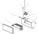
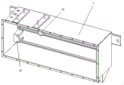
FIG. 1 is an exploded view of the overall structure of the present invention;
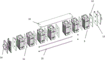
fig. 2 is an overall exploded view of the battery module of the present invention;
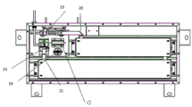
FIG. 3 is a schematic view of the high-voltage control system of the present invention;
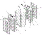
fig. 4 is a schematic view of a battery module according to the present invention;
FIG. 5 is a schematic view of the serial bus of the present invention;
FIG. 6 is a schematic view of an end bus bar of the present invention;
fig. 7 is a schematic view of the box body of the present invention.
Reference numerals: 1-a box body; 2-box cover; 3, communication aviation plug; 4-a negative connection terminal; 5-a positive connection terminal; 6-a battery module; 7-high pressure control system; 8-a battery system control module; 9-a battery module; 10-a protective cover; 11-a series bus; 12-an end bus; 13-an insulating plate; 14-a mounting bracket; 15-screw rod; 16-an electrically controlled relay; 17-a pre-charge resistor; 18-a pre-charge relay; 19-a flow divider; 20-negative connection line; 21-positive connection line; 22-positive support; 23-a negative support; 24-18650 cells; 25-positive collector plate; 26-negative pole collector plate; 27-a resilient contact; 28-cylindrical grooves; 29-buckling; 30-a harness securing structure; 31-a contact; 32-flanging; 33-connecting the stent.
Detailed Description
Examples
The utility model relates to an electric automobile power battery system, as shown in fig. 1, fig. 2, fig. 3, including box 1, box 1 upper cover closes a sealed case lid 2 that links to each other, states that box 1 is equipped with positive connecting terminal 5, negative connecting terminal 4 and communication boat and inserts 3 outward, is equipped with at least one battery module 6, high-pressure control system 7 and battery system control module 8 in the box 1, battery module 6 links to each other with battery system control module 8, high-pressure control system 7 respectively, and battery system control module 8 links to each other with high-pressure control system 7, high-pressure control system 7 links to each other with positive connecting terminal 5 and negative connecting terminal 4 outside being located box 1 respectively; the battery module 6 comprises a plurality of battery modules 9, a protective cover 10, an insulating plate 13, a serial bus bar 11, an end bus bar 12, a mounting bracket 14 and a screw rod 15 which are connected in series, wherein the serial bus bar 11 is arranged between the adjacent battery modules 9 connected in series, the end bus bar 12, the insulating plate 13 and the mounting bracket 14 are sequentially arranged at two ends of the outermost side of each battery module 9 from inside to outside, the screw rod 15 sequentially penetrates through the mounting bracket 14, the insulating plate 13, the end bus bar 12 and the battery modules 9 from one end and penetrates out of the mounting bracket 14 at the other end to connect the battery modules 9 into a whole in series, and the protective cover 10 is arranged at the top of each battery module 9. The high-voltage control system 7 comprises an electric control relay 16, a pre-charging resistor 17, a pre-charging relay 18, a shunt 19, a positive connecting wire 21 and a negative connecting wire 20, wherein the electric control relay 16 is respectively connected with the pre-charging resistor 17, the pre-charging relay 18 and the shunt 19, one end of the positive connecting wire 21 is connected with the electric control relay 16, the other end of the positive connecting wire is connected with the positive pole of the battery module 6, one end of the negative connecting wire 20 is connected with the shunt 19, and the other end of the negative connecting wire is connected with the.
As shown in fig. 4, 5, 6, and 7, the battery module 9 includes a positive electrode support 22, a negative electrode support 23, and a plurality of 18650 electric cores 24 that are identical in structure and are symmetrically arranged with respect to each other, the 18650 electric cores 24 are all installed between the positive electrode support 22 and the negative electrode support 23, the outer wall of the positive electrode support 22 is connected with a positive electrode bus bar 25 through a screw thread, the outer wall of the negative electrode support 23 is connected with a negative electrode bus bar 26 through a screw thread, the inner walls of the positive electrode support 22 and the negative electrode support 23 are further provided with cylindrical grooves 28 that are matched with the 18650 electric cores 24, the positive electrode bus bar 25 and the conflux negative electrode plate 26 are both provided with elastic contacts 3127, the elastic contacts 3127 are connected with the positive and negative electrodes of the 18650 electric cores 24 in a one-to-one correspondence manner, the positive electrode support 22 and the negative electrode support 23 are buckled with each other through a buckle. The serial bus bar 11 is provided with a plurality of contacts 31, the top of the end bus bar 12 is provided with a flange 32, and the end bus bar 12 and the battery module 9 can be connected through the flange 32 in a threaded manner. The box body 1 is provided with a connecting support 33 corresponding to the positions of the battery module 6 and the high-voltage control system 7, and the connecting support 33 is in threaded connection with the battery module 6 and the high-voltage control system 7 respectively.
In this embodiment, the box body 1 is made of high-strength metal plates, the communication aerial plug 3 is used for communication control of the battery system control module 8 and the whole vehicle, the explosion-proof device is used for balancing the pressure inside and outside the battery system and for pressure relief of high-pressure gas inside the power battery system under abnormal conditions, the battery modules 6 in the box body 1 are arranged in two rows, the battery modules 6 are arranged in two rows, one battery module 9 on the outermost side of the battery module 6 is positive and is connected with the high-pressure control system 7 through a positive connecting wire 21, the other battery module is negative and is connected with the high-pressure control system 7 through a negative connecting wire 20, the battery modules 6 are connected in series, the arranged battery system control module 8 is a BMS battery management system, the arranged high-pressure control system 7 comprises a plurality of electronic devices, wherein the electronic control relay 16 is used for on-off of, the type of the pre-charging relay 18 and the pre-charging resistor 17 are used for smoothing current of the whole system at the initial stage of discharging, and impact of abnormal large current on the system is avoided, the type of the pre-charging relay 18 is JCQD10, the type of the pre-charging resistor 17 is EVRX24-100W-75 ohm in the embodiment, the shunt 19 is used for current collection of the whole system, whether discharging current or charging current is purchased through the shunt 19 and then uploaded to the battery system control module 8, the connecting support 33 is arranged in a C shape, and the connecting support 33 fixes the battery module 6 and the high-voltage control system 7 through threads.
In this embodiment, the protective cover 10 can be used to protect the entire battery module 6 from external interference, so as to improve the safety of the battery module 6, the protective cover 10 is made of flame-retardant plastic, so as to improve the flame retardancy of the system, and the protective cover is covered on the battery module 9 through threaded connection, so as to facilitate mounting and dismounting; after the serial bus bar 11 is assembled and compressed, the contact 31 ensures the stability of the serial connection of the battery modules 9 at two sides, and can also ensure that the battery modules 9 cannot be disconnected under certain displacement conditions, thereby improving the mechanical and electrical properties of the system under severe working conditions such as high-frequency vibration and the like; installing support 14 adopts panel beating or aluminum alloy to make, be equipped with a plurality of screw holes on installing support 14, link to each other with box 1 through the screw thread, insulating board 13 can guarantee to be insulating between battery module 9 and the installing support 14, insulating board 13 adopts insulating fire-retardant material, like PC + fire-retardant ABS, can improve the security performance of whole battery module 6, its size of tip busbar 12 is the same with battery module 9, and according to the electric current size definition thickness, T2 red copper also can be chooseed for use to pure aluminium such as the optional 1070 of material.
In this embodiment, the positive bus plate 25 and the negative bus plate 26 may be made of nickel-plated steel sheet and nickel-plated copper sheet, and the elastic contact 3127 may be made in different forms according to practical applications, such as a circular contact 31, for example, the contact 31 may be embossed to position a concave point, for example, the direction of the contact 31 may be arbitrary, and the like. The buckles 29 are arranged in a matched mode, the buckle 29 on the positive electrode support 22 is of a protruding structure, the negative electrode support 23 is of a concave structure, and therefore accurate positioning and effective fastening of the battery cell can be guaranteed when the positive electrode support 23 and the negative electrode support 23 are installed.
Claims (5)
1. A power battery system of an electric automobile comprises a box body (1), wherein a box cover (2) which is connected in a sealing mode is covered on the box body (1), and the power battery system is characterized in that a positive connecting terminal (5), a negative connecting terminal (4) and a communication aerial plug (3) are arranged outside the box body (1), at least one battery module (6), a high-voltage control system (7) and a battery system control module (8) are arranged in the box body (1), the battery module (6) is respectively connected with the battery system control module (8) and the high-voltage control system (7), the battery system control module (8) is connected with the high-voltage control system (7), and the high-voltage control system (7) is respectively connected with the positive connecting terminal (5) and the negative connecting terminal (4) which are positioned outside the box body (1);
the battery module (6) comprises a plurality of battery modules (9) connected in series, a protective cover (10), an insulating plate (13), a serial bus bar (11), an end bus bar (12), a mounting bracket (14) and a screw rod (15), wherein the serial bus bar (11) is arranged between the battery modules (9) connected in series adjacently, the end bus bar (12), the insulating plate (13) and the mounting bracket (14) are sequentially arranged at the two outermost ends of the battery modules (9) from inside to outside, the screw rod (15) sequentially penetrates through the end mounting bracket (14), the insulating plate (13), the end bus bar (12) and the battery modules (9) and penetrates out of the other end mounting bracket (14), the battery modules (9) are connected in series into a whole, and the protective cover (10) is arranged at the top of the battery modules (9).
2. The electric vehicle power battery system according to claim 1, characterized in that the high voltage control system (7) comprises an electric control relay (16), a pre-charging resistor (17), a pre-charging relay (18), a shunt (19), a positive connecting line (21) and a negative connecting line (20), the electric control relay (16) is respectively connected with the pre-charging resistor (17), the pre-charging relay (18) and the shunt (19), wherein one end of the positive connecting line (21) is connected with the electric control relay (16), the other end of the positive connecting line is connected with the positive pole of the battery module (6), one end of the negative connecting line (20) is connected with the shunt (19), and the other end of the negative connecting line is connected with the negative pole of the battery module (6).
3. The electric vehicle power battery system as claimed in claim 1, wherein the battery module (9) comprises a positive electrode bracket (22), a negative electrode bracket (23) and a plurality of 18650 cells (24) which are identical in structure and are arranged symmetrically with each other, the 18650 cells (24) are all installed between the positive electrode bracket (22) and the negative electrode bracket (23), an outer wall of the positive electrode bracket (22) is connected with a positive electrode bus bar (25) through a screw thread, an outer wall of the negative electrode bracket (23) is connected with a negative electrode bus bar (26) through a screw thread, cylindrical grooves (28) matched with the 18650 cells (24) are further arranged on inner walls of the positive electrode bracket (22) and the negative electrode bracket (23), elastic contacts (27) are arranged on the positive electrode bus bar (25) and the negative electrode bus bar (26), the elastic contacts (27) are connected with positive and negative electrodes of the 18650 cells (24) in a one-to one correspondence manner, and the positive electrode bracket (22) and the negative electrode bracket (23) are buckled with each other through a buckle (, and the tops of the positive support (22) and the negative support (23) are respectively provided with a wire harness fixing structure (30).
4. The power battery system of the electric automobile according to claim 1, characterized in that a plurality of contacts (31) are arranged on the serial bus bar (11), a flanging (32) is arranged on the top of the end bus bar (12), and the end bus bar (12) and the battery module (9) can be connected through the flanging (32) in a threaded manner.
5. The power battery system of the electric automobile according to claim 1, characterized in that the box body (1) is provided with a connecting bracket (33) corresponding to the battery module (6) and the high-voltage control system (7), and the connecting bracket (33) is respectively in threaded connection with the battery module (6) and the high-voltage control system (7).
Priority Applications (1)
| Application Number | Priority Date | Filing Date | Title |
|---|---|---|---|
| CN201921461463.2U CN210467917U (en) | 2019-09-04 | 2019-09-04 | Power battery system of electric automobile |
Applications Claiming Priority (1)
| Application Number | Priority Date | Filing Date | Title |
|---|---|---|---|
| CN201921461463.2U CN210467917U (en) | 2019-09-04 | 2019-09-04 | Power battery system of electric automobile |
Publications (1)
| Publication Number | Publication Date |
|---|---|
| CN210467917U true CN210467917U (en) | 2020-05-05 |
Family
ID=70431250
Family Applications (1)
| Application Number | Title | Priority Date | Filing Date |
|---|---|---|---|
| CN201921461463.2U Active CN210467917U (en) | 2019-09-04 | 2019-09-04 | Power battery system of electric automobile |
Country Status (1)
| Country | Link |
|---|---|
| CN (1) | CN210467917U (en) |
Cited By (1)
| Publication number | Priority date | Publication date | Assignee | Title |
|---|---|---|---|---|
| CN112654190A (en) * | 2020-12-21 | 2021-04-13 | 孚能科技(赣州)股份有限公司 | High-voltage distribution box, lower shell assembly thereof, power battery system and automobile |
-
2019
- 2019-09-04 CN CN201921461463.2U patent/CN210467917U/en active Active
Cited By (1)
| Publication number | Priority date | Publication date | Assignee | Title |
|---|---|---|---|---|
| CN112654190A (en) * | 2020-12-21 | 2021-04-13 | 孚能科技(赣州)股份有限公司 | High-voltage distribution box, lower shell assembly thereof, power battery system and automobile |
Similar Documents
| Publication | Publication Date | Title |
|---|---|---|
| CN103481792B (en) | A kind of high voltage distribution box of electrokinetic cell | |
| CN102306717B (en) | Lithium ion power battery pack for electric automobile and manufacturing method of lithium ion power battery pack | |
| CN204651430U (en) | Battery modules voltage acquisition assembly and there is the battery modules of this voltage acquisition assembly | |
| CN210897528U (en) | Modular standard battery box | |
| KR101136806B1 (en) | Electrode Terminal Connecting Device and Battery Module Assembly Employed with the Same | |
| CN109742304A (en) | A kind of power battery module and electric vehicle | |
| CN210467917U (en) | Power battery system of electric automobile | |
| CN112635883B (en) | New energy automobile battery package | |
| EP3790080B1 (en) | Battery module and battery pack | |
| CN210092194U (en) | Commodity circulation car battery system | |
| CN205303200U (en) | Lithium ion capacitor module | |
| CN111668435A (en) | Vehicle-mounted battery and vehicle with same | |
| CN217134554U (en) | Battery and electric equipment | |
| CN115843398B (en) | Battery, electric device, method and equipment for preparing battery | |
| CN210182526U (en) | High-voltage box for power battery pack | |
| CN211844309U (en) | Integrated power battery assembly and automobile | |
| CN115968515A (en) | Battery, electric equipment, method and equipment for preparing battery | |
| CN111668434B (en) | Battery module and vehicle with same | |
| CN209001012U (en) | The battery case panel of integrated high current-carrying | |
| CN208336319U (en) | A kind of novel power battery echelon utilizes PACK | |
| CN220021224U (en) | Split type high-voltage box and power battery system | |
| CN220290981U (en) | Battery system | |
| CN219739125U (en) | Energy storage plastic battery box with grounding protection function | |
| CN214338258U (en) | Intelligent integrated battery control unit device | |
| CN218677365U (en) | New energy automobile quick change power battery |
Legal Events
| Date | Code | Title | Description |
|---|---|---|---|
| GR01 | Patent grant | ||
| GR01 | Patent grant | ||
| TR01 | Transfer of patent right | ||
| TR01 | Transfer of patent right |
Effective date of registration: 20210317 Address after: 410000 Changsha Economic and Technological Development Zone, Changsha, Hunan Province Patentee after: Changsha Banghua New Energy Technology Co.,Ltd. Address before: 723100 east section of Liangzhou Road, Liangshan Industrial Park, Nanzheng County, Hanzhong City, Shaanxi Province Patentee before: SHAANXI BANGHUA NEW ENERGY POWER Co.,Ltd. |