CN210453931U - Packing carton edge rubber coating device - Google Patents
Packing carton edge rubber coating device Download PDFInfo
- Publication number
- CN210453931U CN210453931U CN201920924888.6U CN201920924888U CN210453931U CN 210453931 U CN210453931 U CN 210453931U CN 201920924888 U CN201920924888 U CN 201920924888U CN 210453931 U CN210453931 U CN 210453931U
- Authority
- CN
- China
- Prior art keywords
- glue
- roller
- frame
- band conveyer
- supporting
- Prior art date
- Legal status (The legal status is an assumption and is not a legal conclusion. Google has not performed a legal analysis and makes no representation as to the accuracy of the status listed.)
- Active
Links
Images


Abstract
Packing carton edge rubber coating device, including band conveyer, there is the backup pad at band conveyer frame both sides difference fixed mounting, it stores up the gluey groove to be equipped with between two backup pads, there are two pivots at two backup pads of storing up gluey groove below upper shaft coupling, install a plurality of glue roller in one of them pivot, it has many glue outlet pipe to put through on each glue roller top glue storage groove, each glue outlet pipe lower extreme supports respectively to lean on each glue roller periphery, install a plurality of glue roller in another pivot, each glue roller periphery is pasted on each glue roller periphery, gear drive is passed through to two pivot one end and is connected, one of them other one end of pivot is passed through sprocket feed mechanism and is connected with band conveyer transmission. The utility model discloses can evenly paint glue to the packing carton edge.
Description
Technical Field
The utility model relates to a packing carton edge rubber coating device.
Background
Packing carton includes the welt and pastes the wrapping paper on welt surface, and wrapping paper bordures the welt in some packing carton, and this back of need the workman to carry out the rubber coating to the welt edge, and current mode of pasting is that the workman uses the brush to paint glue, in order to guarantee the effect of borduring of packing carton, generally can brush some glue more, on the one hand can leave unnecessary glue vestige on welt surface, influence packing carton outward appearance, and on the other hand is artifical rubber coating high in labor strength.
SUMMERY OF THE UTILITY MODEL
The to-be-solved technical problem of the utility model is to provide packing carton edge rubber coating device, can evenly paint glue to the packing carton edge.
In order to solve the above problem, the to-be-solved technical scheme of the utility model is:
packing carton edge rubber coating device, including band conveyer, there is the backup pad at band conveyer frame both sides difference fixed mounting, it stores up the gluey groove to be equipped with between two backup pads, there are two pivots at two backup pads of storing up gluey groove below upper shaft coupling, install a plurality of glue roller in one of them pivot, it has many glue outlet pipe to put through on each glue roller top glue storage groove, each glue outlet pipe lower extreme supports respectively to lean on each glue roller periphery, install a plurality of glue roller in another pivot, each glue roller periphery is pasted on each glue roller periphery, gear drive is passed through to two pivot one end and is connected, one of them other one end of pivot is passed through sprocket feed mechanism and is connected with band conveyer transmission.
A support shaft is arranged on a frame below the belt surface of the belt conveyor, a support roller is arranged on the support shaft, the support roller and a glue spreader are symmetrically arranged on two sides of the belt surface, and the belt surface of the belt conveyor moves on the surface of the support roller.
The supporting shaft is connected with the belt conveyor frame through a set of jacking mechanism at two ends respectively, the jacking mechanism comprises a waist-shaped hole formed in the frame, two sides of the waist-shaped hole are respectively and fixedly connected with a guide bar, a bearing seat is arranged between the two guide bars, one end of the supporting shaft penetrates through the waist-shaped hole and then is connected with the bearing seat, a top plate is fixedly connected to the frame below the bearing seat, a jack screw is installed on the top plate, a spring is arranged between the bearing seat and the frame, and the spring pushes the bearing seat to abut against the jack screw.
The two guide plates are respectively arranged on the belt surface of the belt conveyor and are connected with the belt conveyor frame through a plurality of connecting frames, a channel is formed by the two guide plates at the surface of the belt conveyor at intervals, and one end, far away from the glue roller, of the channel is horn-shaped.
The technical effects of the utility model are that: at the in-process that the packing carton cardboard was carried on band conveyer, on the glue spreader that glue roller will store up glue tank glue and scribble, scribble the packing carton cardboard edge of below process with glue by the glue spreader, realize improving rubber coating efficiency to the even rubber coating at packing carton cardboard edge, make the rubber coating more even.
Drawings
The invention will be further explained with reference to the drawings:
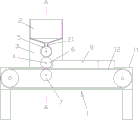
FIG. 1 is a schematic view of the front view structure of the present invention,
figure 2 is a schematic top view of the present invention,
FIG. 3 is a schematic cross-sectional view taken along line A-A in FIG. 1,
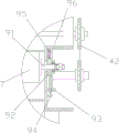
figure 4 is a schematic view of a partially enlarged structure at B in figure 3,
fig. 5 is a partial right view of the present invention.
In the figure: the rubber coating machine comprises a belt conveyor 1, a rubber storage tank 2, a supporting plate 3, a rotating shaft 4, a rubber roller 5, a rubber coating roller 6, a supporting roller 7, a guide plate 8, a jacking mechanism 9, a rack 11, a belt surface 12, a rubber outlet pipe 21, a gear 41, a chain wheel transmission mechanism 42, a connecting frame 81, a supporting shaft 91, a bearing seat 92, a top plate 93, a top thread 94, a spring 95 and a guide strip 96.
Detailed Description
As shown in figures 1 to 3, the packing box edge gluing device comprises a belt conveyor 1, wherein two sides of a frame 11 of the belt conveyor 1 are respectively and fixedly provided with a support plate 3, a glue storage groove 2 is arranged between the two support plates 3, two support plates 3 below the glue storage groove 2 are in shaft connection with two rotating shafts 4, one rotating shaft 4 is provided with a plurality of glue rollers 5, the glue storage groove 2 above each glue roller 5 is communicated with a plurality of glue outlet pipes 21, the lower ends of the glue outlet pipes 21 are respectively abutted against the circumferential surface of each glue roller 5, the other rotating shaft 4 is provided with a plurality of glue rollers 6, the circumferential surface of each glue roller 6 is abutted against the circumferential surface of each glue roller 5, one end of a roller of the belt conveyor 1 is connected with a chain wheel, one end of the two rotating shafts 4 is in transmission connection through a gear 41, the other end of one rotating shaft 4 is in transmission connection with the belt conveyor 1 through a chain wheel transmission mechanism 42, in the process that the belt conveyor 1 takes the packing box paperboard to pass through the glue spreader 6, the glue spreader 6 is pressed on the surface of the packing box paperboard, and two glue spreaders 6 in figure 3 just correspond to the edges of two ends of the packing box lining plate.
The utility model discloses a working process does: band conveyer 1 transportation cardboard removes from glue roller 5 below, and at this in-process, band conveyer 1 drives glue spreader 6 and glue roller 5 synchronous revolution through chain drive mechanism, and glue roller 5 paints glue spreader 6 after taking out glue in glue storage tank 2, and then glue spreader 6 paints the welt both ends edge with glue, accomplishes to paint welt both ends edge glue.
As shown in fig. 4 and 5, a supporting shaft 91 is installed on the frame 11 below the belt surface of the belt conveyor 1, a supporting roller 7 is installed on the supporting shaft 91, the supporting roller 7 and the glue spreader 6 are symmetrically arranged on two sides of the belt surface, and the belt surface of the belt conveyor 1 moves on the surface of the supporting roller 7. The supporting roller 7 is used for preventing the glue spreading roller 6 from pressing the packing box lining plate, the supporting roller 7 supports the lining plate, and the phenomenon that the lining plate is not uniformly spread due to depression of the lining plate is avoided.
Two ends of the supporting shaft 91 are respectively connected with a frame 11 of the belt conveyor 1 through a group of jacking mechanisms 9, each jacking mechanism 9 comprises a waist-shaped hole arranged on the frame 11, two sides of the waist-shaped hole are respectively fixedly connected with a guide strip 96, a bearing seat 92 is arranged between the two guide strips 96, one end of the supporting shaft 91 passes through the waist-shaped hole and then is connected with the bearing seat 92, a top plate 93 is fixedly connected on the frame 11 below the bearing seat 92, a jackscrew 94 is arranged on the top plate 93, a spring 95 is arranged between the bearing seat 92 and the frame 11, the spring 95 pushes the bearing seat 92 to abut against the jackscrew 94, in the using process, the supporting shaft 91 can be pushed to move up and down in the kidney-shaped hole by rotating the jackscrew 94, so as to adjust the height position of the bearing seat 92, and then finely adjust the interval between back shaft 91 and glue spreader 6, make it can carry out the rubber coating to different thickness packing carton cardboard edge.
Be equipped with two baffle 8 on band conveyer 1 belt face respectively, two baffle 8 are connected with band conveyer 1 frame 11 through a plurality of link 81, by two baffle 8 at 1 surperficial interval play of band conveyer a passageway, the passageway is kept away from 5 one end of glue roller for tubaeform. In the process that belt conveyor 1 takes the cardboard to remove, lead by two blocks of baffle 8 to the packing carton cardboard, make packing carton cardboard both ends edge can aim at glue spreader 6, improve packing carton cardboard gummed accuracy.
Claims (4)
1. Packing carton edge rubber coating device includes band conveyer (1), its characterized in that: supporting plates (3) are respectively and fixedly arranged on two sides of a frame (11) of the belt conveyor (1), a glue storage groove (2) is arranged between the two supporting plates (3), the two supporting plates (3) below the glue storage groove (2) are connected with two rotating shafts (4) in an upper shaft way, a plurality of glue rollers (5) are arranged on one rotating shaft (4), a plurality of glue outlet pipes (21) are communicated with the glue storage groove (2) above each glue roller (5), the lower ends of the glue outlet pipes (21) are respectively abutted against the circumferential surface of each glue roller (5), a plurality of glue coating rollers (6) are arranged on the other rotating shaft (4), the circumferential surface of each glue coating roller (6) is attached to the circumferential surface of each glue roller (5), one ends of the two rotating shafts (4) are in transmission connection through a gear (41), the other end of one rotating shaft (4) is in transmission connection with the belt conveyor (1) through a chain wheel transmission mechanism (42).
2. The apparatus for gluing the edge of a packing box according to claim 1, wherein: a supporting shaft (91) is installed on a rack (11) below the belt surface of a belt conveyor (1), a supporting roller (7) is installed on the supporting shaft (91), the supporting roller (7) and a glue spreader (6) are symmetrically arranged on two sides of the belt surface, and the belt surface of the belt conveyor (1) moves on the surface of the supporting roller (7).
3. The apparatus for gluing the edge of a packing box according to claim 2, wherein: back shaft (91) both ends are connected with band conveyer (1) frame (11) through a set of climbing mechanism (9) respectively, climbing mechanism (9) are including seting up the waist type hole in frame (11), at waist type hole both sides fixedly connected with conducting bar (96) respectively, be equipped with bearing frame (92) between two conducting bar (96), back shaft (91) one end is passed and is connected with bearing frame (92) behind the waist type hole, fixedly connected with roof (93) on bearing frame (92) below frame (11), install jackscrew (94) on roof (93), be equipped with spring (95) between bearing frame (92) and frame (11), spring (95) ejection bearing frame (92) are supported and are leaned on jackscrew (94).
4. The apparatus for gumming an edge of a packing box as set forth in any one of claims 1 to 3, wherein: be equipped with two baffle (8) respectively on band conveyer (1) belt face, two baffle (8) are connected with band conveyer (1) frame (11) through a plurality of link (81), are kept away from glue roller (5) one end by two baffle (8) and are horn shape at band conveyer (1) surface interval play a passageway, passageway.
Priority Applications (1)
| Application Number | Priority Date | Filing Date | Title |
|---|---|---|---|
| CN201920924888.6U CN210453931U (en) | 2019-06-19 | 2019-06-19 | Packing carton edge rubber coating device |
Applications Claiming Priority (1)
| Application Number | Priority Date | Filing Date | Title |
|---|---|---|---|
| CN201920924888.6U CN210453931U (en) | 2019-06-19 | 2019-06-19 | Packing carton edge rubber coating device |
Publications (1)
| Publication Number | Publication Date |
|---|---|
| CN210453931U true CN210453931U (en) | 2020-05-05 |
Family
ID=70441442
Family Applications (1)
| Application Number | Title | Priority Date | Filing Date |
|---|---|---|---|
| CN201920924888.6U Active CN210453931U (en) | 2019-06-19 | 2019-06-19 | Packing carton edge rubber coating device |
Country Status (1)
| Country | Link |
|---|---|
| CN (1) | CN210453931U (en) |
Cited By (1)
| Publication number | Priority date | Publication date | Assignee | Title |
|---|---|---|---|---|
| CN114453206A (en) * | 2022-02-21 | 2022-05-10 | 湖北泰友纸业有限公司 | Glue constant-temperature smearing device for corrugated paper production |
-
2019
- 2019-06-19 CN CN201920924888.6U patent/CN210453931U/en active Active
Cited By (1)
| Publication number | Priority date | Publication date | Assignee | Title |
|---|---|---|---|---|
| CN114453206A (en) * | 2022-02-21 | 2022-05-10 | 湖北泰友纸业有限公司 | Glue constant-temperature smearing device for corrugated paper production |
Similar Documents
| Publication | Publication Date | Title |
|---|---|---|
| CN205739572U (en) | Cardboard box printing feed guide device | |
| CN206030708U (en) | Automatic laminating machine of glass | |
| CN210453931U (en) | Packing carton edge rubber coating device | |
| CN208558425U (en) | A kind of automatic box-folding corner pasting machine | |
| CN210436688U (en) | Improve full-automatic case gluing machine of viscose effect | |
| CN207327704U (en) | Packing case bonds gumming mechanism | |
| CN218834996U (en) | Cardboard box glue spreader | |
| CN114194515B (en) | Carton packer | |
| CN208558427U (en) | A kind of automatic carton corner pasting machine | |
| CN109178528B (en) | Two-sided labeller's of carton streamlined device | |
| CN214354560U (en) | Corrugated paper rubberizing device | |
| CN211616760U (en) | Cigarette case forming machine | |
| CN209479091U (en) | Automatic bottom sticking machine | |
| CN216885396U (en) | Paper feeding device additionally arranged for paperboard box pasting machine | |
| CN203611497U (en) | Automatic paperboard feeding workbench of double paperboard stitcher | |
| CN216965115U (en) | Automatic bag sealer of photovoltaic module | |
| CN206307356U (en) | A kind of carton packing machine | |
| CN214812111U (en) | Glue dispensing mechanism of multi-liner carton packaging machine | |
| CN218084427U (en) | Packing gift box printing is with pasting case device | |
| CN216579401U (en) | Automatic gluing mechanism of full-automatic box pasting machine | |
| CN212328742U (en) | Full-automatic packing carton rubberizing device | |
| CN112478234B (en) | Automatic packaging device for firework pot finished products | |
| CN216100659U (en) | Automatic bottom-sticking forming machine for paper tube processing | |
| CN210477937U (en) | A rubber coating subassembly for cardboard side spreading machine | |
| CN219338762U (en) | Guide wheel set for pasting paper box |
Legal Events
| Date | Code | Title | Description |
|---|---|---|---|
| GR01 | Patent grant | ||
| GR01 | Patent grant |