CN210451943U - Special fixture for throttle valve side flange - Google Patents
Special fixture for throttle valve side flange Download PDFInfo
- Publication number
- CN210451943U CN210451943U CN201920162102.1U CN201920162102U CN210451943U CN 210451943 U CN210451943 U CN 210451943U CN 201920162102 U CN201920162102 U CN 201920162102U CN 210451943 U CN210451943 U CN 210451943U
- Authority
- CN
- China
- Prior art keywords
- chassis
- throttle valve
- pressing plate
- positioning block
- supporting frame
- Prior art date
- Legal status (The legal status is an assumption and is not a legal conclusion. Google has not performed a legal analysis and makes no representation as to the accuracy of the status listed.)
- Expired - Fee Related
Links
Images
Abstract
The utility model relates to the field of machine manufacturing, in particular to a special clamp for a side flange of a throttle valve; the method is characterized in that: comprises a chassis, a supporting frame, a positioning block, a pull rod, a pressing plate, a pressing block, a balance weight and an arch-shaped clamp; the supporting frame is vertically arranged on the chassis, a positioning block is arranged on the side face of the supporting frame, an arch clamp is arranged at the top of the positioning block, a pressing plate is arranged opposite to the positioning block, a pressing block is arranged on the pressing plate, a balance weight is arranged beside the pressing plate, and a pull rod is arranged beside the supporting frame; the throttle valve is erected on the chassis and fastened through the combination of the support frame, the positioning block, the pressing plate and the pressing block, the arch-shaped clamp is used for limiting the upper structure of the throttle valve, the balancing weight is used for enabling the weight of the chassis loaded with the throttle valve to be uniformly distributed, and the support frame is firmly fixed on the chassis through the pull rod. The special fixture can avoid the resonance phenomenon of the cutting force on the main shaft and improve the stability of the fixture and the material blank in the machining process.
Description
Technical Field
The utility model relates to the field of machine-building, specifically a special fixture of choke valve side flange.
Background
The shape of the throttle valve body is forged and irregular, and common three-jaw clamping cannot be finished; the requirements of geometric tolerance between each hole and each end face are difficult to be ensured. In order to solve the problems, a complex calibration tool is used for detecting the processing surface in the processing process, the operation process often reduces the production efficiency, and the uniformity of the processing quality is difficult to ensure due to the complex detection process.
Disclosure of Invention
An object of the utility model is to overcome above-mentioned defect, provide a special fixture convenient to throttle valve side flange processing and can guarantee processingquality.
In order to achieve the above object, the present invention is realized as follows:
a special clamp for a throttle valve side flange comprises a chassis, a support frame, a positioning block, a pull rod, a pressing plate, a pressing block, a balance weight and an arch-shaped clamp; the supporting frame is vertically arranged on the chassis, a positioning block is arranged on the side face of the supporting frame, an arch clamp is arranged at the top of the positioning block, a pressing plate is arranged opposite to the positioning block, a pressing block is arranged on the pressing plate, a balance weight is arranged beside the pressing plate, and a pull rod is arranged beside the supporting frame; the throttle valve is erected on the chassis and fastened through the combination of the support frame, the positioning block, the pressing plate and the pressing block, the arch-shaped clamp is used for limiting the upper structure of the throttle valve, the balancing weight is used for enabling the weight of the chassis loaded with the throttle valve to be uniformly distributed, and the support frame is firmly fixed on the chassis through the pull rod.
The action principle of the clamp is as follows: the chassis is directly connected with a main shaft of the processing equipment; meanwhile, the chassis and the support frame are combined and locked by bolts, the center distance is finely adjusted by moving the bolts in the second process, the side face of the support frame is ensured to be vertical to the chassis, and the pull rods on the two sides ensure the stability of the chassis in rotation; the positioning block is connected to the support frame through a hole shaft in a matching way; the blank is overlapped on the locating piece to compress tightly the work piece through the clamp plate, the bow clamp then supports on the excircle at blank top, improves stability, carries out machining at last, and then guarantees dimensional tolerance.
The special fixture has the advantages that the chassis is directly connected with the lathe spindle, the overhang distance of the blank can be shortened, the center of gravity of the blank is closer to the spindle, the phenomenon that the cutting force generates resonance on the spindle is avoided, and the stability of the fixture and the blank in the machining process is improved.
Drawings
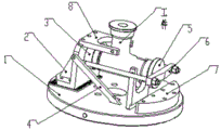
Fig. 1 is a schematic view of the use state of the clamp.
Detailed Description
The invention is further illustrated by the following specific examples.
As shown in fig. 1, a special fixture for a throttle side flange comprises a chassis 1, a support frame 2, a positioning block 3, a pull rod 4, a pressure plate 6, a pressing block 5, a balancing weight 7 and an arch clamp 8; the supporting frame 2 is vertically arranged on the chassis 1, a positioning block 3 is arranged on the side face of the supporting frame 2, an arch clamp 8 is arranged at the top of the positioning block 3, a pressing plate 6 is arranged opposite to the positioning block 3, a pressing block 5 is arranged on the pressing plate 6, a balancing weight 7 is arranged beside the pressing plate 6, and a pull rod 4 is arranged beside the supporting frame 2; make the throttle valve erect on chassis 1 and fasten through the combination of support frame 2, locating piece 3, clamp plate 6 and compact heap 5, and bow-shaped clamp 8 is used for spacing the superstructure of throttle valve, and balancing weight 7 is used for making the chassis 1 weight distribution who carries the throttle valve even, and pull rod 4 ensures that support frame 2 is fixed on chassis 1 firmly.
The action principle of the clamp is as follows: the chassis is directly connected with a main shaft of the processing equipment; meanwhile, the chassis and the support frame are combined and locked by bolts, the center distance is finely adjusted by moving the bolts in the second process, the side face of the support frame is ensured to be vertical to the chassis, and the pull rods on the two sides ensure the stability of the chassis in rotation; the positioning block is connected to the support frame through a hole shaft in a matching way; the blank is overlapped on the locating piece to compress tightly the work piece through the clamp plate, the bow clamp then supports on the excircle at blank top, improves stability, carries out machining at last, and then guarantees dimensional tolerance.
The special fixture has the advantages that the chassis is directly connected with the lathe spindle, the overhang distance of the blank can be shortened, the center of gravity of the blank is closer to the spindle, the phenomenon that the cutting force generates resonance on the spindle is avoided, and the stability of the fixture and the blank in the machining process is improved.
Claims (1)
1. The utility model provides a special fixture of choke valve side flange which characterized in that: comprises a chassis, a supporting frame, a positioning block, a pull rod, a pressing plate, a pressing block, a balancing weight and an arch-shaped clamp; the supporting frame is vertically arranged on the chassis, a positioning block is arranged on the side face of the supporting frame, an arch clamp is arranged at the top of the positioning block, a pressing plate is arranged opposite to the positioning block, a pressing block is arranged on the pressing plate, a balancing weight is arranged beside the pressing plate, and a pull rod is arranged beside the supporting frame; the throttle valve is erected on the chassis and fastened through the combination of the support frame, the positioning block, the pressing plate and the pressing block, the arch-shaped clamp is used for limiting the upper structure of the throttle valve, the balancing weight is used for enabling the weight of the chassis loaded with the throttle valve to be uniformly distributed, and the support frame is firmly fixed on the chassis through the pull rod.
Priority Applications (1)
| Application Number | Priority Date | Filing Date | Title |
|---|---|---|---|
| CN201920162102.1U CN210451943U (en) | 2019-01-30 | 2019-01-30 | Special fixture for throttle valve side flange |
Applications Claiming Priority (1)
| Application Number | Priority Date | Filing Date | Title |
|---|---|---|---|
| CN201920162102.1U CN210451943U (en) | 2019-01-30 | 2019-01-30 | Special fixture for throttle valve side flange |
Publications (1)
| Publication Number | Publication Date |
|---|---|
| CN210451943U true CN210451943U (en) | 2020-05-05 |
Family
ID=70428428
Family Applications (1)
| Application Number | Title | Priority Date | Filing Date |
|---|---|---|---|
| CN201920162102.1U Expired - Fee Related CN210451943U (en) | 2019-01-30 | 2019-01-30 | Special fixture for throttle valve side flange |
Country Status (1)
| Country | Link |
|---|---|
| CN (1) | CN210451943U (en) |
-
2019
- 2019-01-30 CN CN201920162102.1U patent/CN210451943U/en not_active Expired - Fee Related
Similar Documents
| Publication | Publication Date | Title |
|---|---|---|
| CN205342590U (en) | Automobile -used anchor clamps of hydraulic pressure cylinder end | |
| CN201792230U (en) | Fixture for draw bar | |
| CN204725191U (en) | Gooseneck shaped piece automobile clamper | |
| CN206883199U (en) | A kind of valve body lathe process clamping tooling | |
| CN106002421A (en) | Special-shaped part turning fixture and application method thereof | |
| CN202087999U (en) | Jig used for machining a brake bottom board | |
| CN205218599U (en) | Module processing upset anchor clamps about forge hot mould | |
| CN205834845U (en) | A kind of turning clamp of special-shaped part | |
| CN202461591U (en) | Special machine tool for balance shaft bracket boring tooling | |
| CN203418337U (en) | Fixture suitable for rapid drilling of rope clip | |
| CN211414375U (en) | CNC axle type part boring grab | |
| CN210451943U (en) | Special fixture for throttle valve side flange | |
| CN202571918U (en) | Frock clamp for machine body facing | |
| CN102205431A (en) | Multi-station processing machine tool for danfoss crank shaft oil hole | |
| CN205147885U (en) | Centre gripping is clamp plate anchor clamps for slewing bearing | |
| CN205096651U (en) | A frock for eccentric T type thread processing of bearing bracket | |
| CN201755675U (en) | Hinge type jig with replaceable jig bushing block | |
| CN207239782U (en) | A kind of train wagons balancing frame processing tool | |
| CN203471077U (en) | Bevel gear clamp | |
| CN102990509B (en) | Blade grinding clamp of silicon steel sheet punching die punch | |
| CN207735975U (en) | A kind of PC beam supports clamping device for processing | |
| CN202377832U (en) | Bearing hole machining fixture for auxiliary shafts of front covers | |
| CN206662301U (en) | A kind of tailstock tool body clamp structure | |
| CN205218820U (en) | Taper hole grinding fixture in main shaft | |
| CN202825343U (en) | Tool used for horizontal boring machine to process rear box body |
Legal Events
| Date | Code | Title | Description |
|---|---|---|---|
| GR01 | Patent grant | ||
| GR01 | Patent grant | ||
| CF01 | Termination of patent right due to non-payment of annual fee |
Granted publication date: 20200505 Termination date: 20220130 |
|
| CF01 | Termination of patent right due to non-payment of annual fee |