CN210430641U - Automatic control heat dissipation regulator cubicle - Google Patents
Automatic control heat dissipation regulator cubicle Download PDFInfo
- Publication number
- CN210430641U CN210430641U CN201921547845.7U CN201921547845U CN210430641U CN 210430641 U CN210430641 U CN 210430641U CN 201921547845 U CN201921547845 U CN 201921547845U CN 210430641 U CN210430641 U CN 210430641U
- Authority
- CN
- China
- Prior art keywords
- cabinet body
- accommodating cavity
- cabinet
- heat dissipation
- driving wheel
- Prior art date
- Legal status (The legal status is an assumption and is not a legal conclusion. Google has not performed a legal analysis and makes no representation as to the accuracy of the status listed.)
- Active
Links
Images


Abstract
The utility model discloses an automatic control heat dissipation regulator cubicle, including the cabinet body and cabinet door, the cabinet door passes through hinge and cabinet body coupling, and cabinet door right side is equipped with handle, its characterized in that: the lower end of the cabinet body is provided with a bottom plate, the bottom surface of the cabinet body and the side wall of the cabinet body enclose a closed accommodating cavity, and the front side of the accommodating cavity is provided with an air inlet channel penetrating through the outside and the accommodating cavity; the bottom plate is uniformly provided with air inlet holes which penetrate through the accommodating cavity and the inner part of the cabinet body; an air exhaust channel which is communicated with the inside and the outside is vertically arranged on the top surface of the cabinet body, an exhaust fan is arranged in the air exhaust channel, a U-shaped cavity is arranged on the inner side of the cabinet body, and an auxiliary heat dissipation device is arranged in the U-shaped cavity; this device makes the circulation of air in the switch board get up through the air exhauster that the top set up and the inlet air duct of bottom design, realizes good cooling effect.
Description
Technical Field
The utility model relates to a switch board technical field, concretely relates to automatic control heat dissipation regulator cubicle.
Background
The control cabinet is formed by assembling switch equipment, measuring instruments, protective electrical appliances and auxiliary equipment in a closed or semi-closed metal cabinet or on a screen according to the electrical wiring requirement, and the arrangement of the control cabinet meets the requirement of normal operation of a power system, is convenient to maintain and does not endanger the safety of people and surrounding equipment; the existing control cabinet has low heat dissipation capacity, and can generate heat in the operation process of equipment, if the heat cannot be dissipated in time, the equipment can be damaged due to temperature rise, and the safety of a user can be seriously threatened; but current rack heat radiation structure design is unreasonable, because the rack only designs a fan on the cabinet door, because the air exit sets up in the below, ventilation effect is poor, reaches due radiating effect, even need open the cabinet door of the rack that fills electric pile when summer, inside and external heat transfer area of radiating cabinet and with external circulation of air to reduce the inside temperature of radiating cabinet.
Disclosure of Invention
An object of the utility model is to provide an automatic control heat dissipation regulator cubicle, this device make the circulation of air in the switch board get up through the air exhauster that the top set up and the inlet air duct of bottom design, realize good cooling effect.
The utility model adopts the technical scheme as follows: an automatic control heat dissipation electrical cabinet comprises a cabinet body and a cabinet door, wherein the cabinet door is connected with the cabinet body through a hinge, a handle is arranged on the right side of the cabinet door, a bottom plate is arranged at the lower end of the cabinet body, a closed accommodating cavity is enclosed by the bottom plate, the bottom surface of the cabinet body and the side wall of the cabinet body, and an air inlet channel penetrating through the outside and the accommodating cavity is arranged on the front side of the accommodating cavity; the bottom plate is uniformly provided with air inlet holes which penetrate through the accommodating cavity and the inner part of the cabinet body; an air exhaust channel which is communicated with the inside and the outside is vertically arranged on the top surface of the cabinet body, and an exhaust fan is arranged in the air exhaust channel;
a U-shaped cavity is formed in the inner side of the cabinet body, fan blade channels are uniformly formed in the inner side wall of the U-shaped cavity, and fan blades are rotationally connected in the U-shaped cavity; the fan blades comprise rotating shafts and rectangular blades, and the upper parts of the rotating shafts are rotatably connected in rotating shaft grooves above the cabinet body; a rotating shaft channel penetrating through the bottom plate is arranged below the rotating shaft and extends into the accommodating cavity, and the rotating shaft channel is rotatably connected to the lower surface of the accommodating cavity; a driving wheel is fixedly connected on the rotating shaft between the bottom plate and the lower surface of the accommodating cavity; a driving motor is fixed on the front side of the lower surface of the accommodating cavity, a driving wheel is welded on a motor shaft of the driving motor, the driving wheel and the driving wheel are positioned on the same horizontal plane, and the driving wheel are in chain transmission connection through a transmission chain;
the front side of the cabinet body is provided with a first switch for controlling the work of the exhaust fan and a second switch for controlling the work of the driving motor.
As optimization, temperature sensors for detecting the temperature in the cabinet body are oppositely arranged on the left side and the right side of the interior of the cabinet body, and a plc is arranged on the rear side of the interior of the cabinet body; and the plc is respectively and electrically connected with the temperature sensor, the driving motor and the exhaust fan.
Preferably, a filter screen is glued in the air inlet channel.
Further, a sealing ring is arranged between the cabinet door and the cabinet body.
The beneficial effects of the utility model reside in that:
1. the air exhaust channel on the top surface of the cabinet body and the air inlet channel on the bottom of the cabinet body cover the inner cavity of the cabinet body, so that comprehensive heat dissipation is performed, and the ventilation and heat dissipation effects are good;
2. when the temperature in the cabinet body rises abnormally, the second switch controls the driving motor to rotate, so that the fan blades in the U-shaped groove are driven to rotate to perform auxiliary heat dissipation, air circulation is quicker, and damage to components in the cabinet body due to abnormal temperature rise is avoided;
3. a filter screen is glued in the air inlet channel to filter external dust and prevent internal dust accumulation;
4. a sealing ring is arranged between the cabinet door and the cabinet body, so that a closed space is formed inside the cabinet body, and when air draft is used for heat dissipation, interference is prevented, and a stable heat dissipation flowing direction is formed.
Drawings
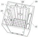
Fig. 1 is a schematic structural diagram of the present invention.
Fig. 2 is a schematic view of the bottom plate structure.
Fig. 3 is a schematic view of the internal structure of the accommodating chamber.
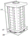
Fig. 4 is a schematic structural view of a U-shaped cavity.
FIG. 5 is a schematic view of a fan blade structure.
Fig. 6 is a schematic structural view of the sealing ring.
Fig. 7 is a circuit connection diagram.
In the figure: the cabinet comprises a cabinet body 1, a cabinet door 2, a handle 3, a bottom plate 4, an accommodating cavity 5, an air inlet channel 6, an air inlet hole 7, an exhaust channel 8, an exhaust fan 9, a U-shaped cavity 10, a fan blade channel 11, fan blades 12, a rotating shaft 13, blades 14, a rotating shaft groove 15, a rotating shaft channel 16, a driving wheel 17, a driving motor 18, a driving wheel 19, a driving chain 20, a temperature sensor 21, plc22, a filter screen 23, a sealing ring 24, a first switch 25 and a second switch 26.
Detailed Description
In order to make the technical solutions of the present invention better understood by those skilled in the art, the present invention will be further described in detail with reference to the accompanying drawings, which are only used for illustrating the technical solutions of the present invention and are not limited.
In the description of the present invention, it is to be understood that the terms "center", "longitudinal", "lateral", "up", "down", "front", "back", "left", "right", "vertical", "horizontal", "top", "bottom", "inner", "outer", and the like, indicate orientations or positional relationships based on those shown in the drawings, and are only for convenience of description and simplicity of description, and do not indicate or imply that the device or element being referred to must have a particular orientation, be constructed and operated in a particular orientation, and therefore, should not be construed as limiting the present invention; furthermore, the terms "first", "second", etc. are used for descriptive purposes only and are not to be construed as indicating or implying relative importance or implicitly indicating the number of technical features indicated; thus, a feature defined as "first," "second," etc. may explicitly or implicitly include one or more of that feature; in the description of the present invention, "a plurality" means two or more unless otherwise specified.
In the description of the present invention, it is to be noted that, unless otherwise explicitly specified or limited, the terms "mounted," "connected," and "connected" are to be construed broadly, and may be, for example, fixedly connected, detachably connected, or integrally connected; can be mechanically or electrically connected; the two components can be directly connected or indirectly connected through an intermediate medium, and the two components can be communicated with each other; the specific meaning of the above terms in the present invention can be understood by those of ordinary skill in the art through specific situations.
An automatic control heat dissipation electrical cabinet comprises a cabinet body 1 and a cabinet door 2, wherein the cabinet door 2 is connected with the cabinet body 1 through a hinge, a handle 3 is arranged on the right side of the cabinet door 2, a bottom plate 4 is arranged at the lower end of the cabinet body 1, a closed accommodating cavity 5 is enclosed by the bottom plate 4, the bottom surface of the cabinet body 1 and the side wall of the cabinet body 1, and an air inlet channel 6 penetrating through the outside and the accommodating cavity 5 is arranged on the front side of the accommodating cavity 5; the bottom plate 4 is uniformly provided with air inlet holes 7 which penetrate through the accommodating cavity 5 and the interior of the cabinet body 1; an air exhaust channel 8 which is communicated with the inside and the outside is vertically arranged on the top surface of the cabinet body 1, and an exhaust fan 9 is arranged in the air exhaust channel 8; the air inlet channel 6 at the bottom of the cabinet body 1 and the air exhaust channel 8 at the top surface of the cabinet body 1 cover the inner cavity of the cabinet body 1 in a stroke manner, so that comprehensive heat dissipation is realized, the ventilation and heat dissipation effects are good, the cabinet body 1 is in a closed state, and the heat dissipation is more stable.
A U-shaped cavity 10 is arranged on the inner side of the cabinet body 1, fan blade channels 11 are uniformly arranged on the inner side wall of the U-shaped cavity 10, and fan blades 12 are rotatably connected in the U-shaped cavity 10; the fan blades 12 comprise rotating shafts 13 and rectangular blades 14, and the upper parts of the rotating shafts 13 are rotatably connected in rotating shaft grooves 15 above the cabinet body 1; a rotating shaft channel 16 passing through the bottom plate 4 below the rotating shaft 13 extends into the accommodating cavity 5 and is rotatably connected with a rotating shaft groove 15 on the lower surface of the accommodating cavity 5; a transmission wheel 17 is fixedly connected to a rotating shaft 13 between the bottom plate 4 and the lower surface of the accommodating cavity 5, the transmission wheel 17 can be selected from a gear or a belt pulley, different fixed connection modes can be selected according to different materials of the selected fan blades 12 and the transmission wheel 17, and if the fan blades 12 and the transmission wheel 17 are made of plastic materials, the fixed mode can be a mode of direct molding by gluing or hot melting; if the fan blades 12 and the driving wheel 17 are made of metal materials, the fixed connection mode can be a welding mode; a driving motor 18 is installed on the front side of the lower surface of the accommodating cavity 5 through a bolt, a driving wheel 19 is connected to a motor shaft of the driving motor 18 in a key mode, the driving wheel 19 is the same as the driving wheel 17, and if the driving wheel 17 is a gear, the driving wheel 19 also is a gear; the driving wheel 19 and the driving wheel 17 are positioned on the same horizontal plane, and the driving wheel 19 and the driving wheel 17 are in transmission connection through a transmission chain 20; the transmission chain 20 is matched with the driving wheel 19 and the transmission wheel 17.
A first switch 25 for controlling the exhaust fan 9 to work and a second switch 26 for controlling the driving motor 18 to work are arranged at the front side of the cabinet 1;
when the temperature in the cabinet body rises, the first switch 25 is turned on to control the exhaust fan 9 to work, when the effect of the exhaust fan 9 is poor when the temperature in the cabinet body continuously rises, the second switch 26 is turned on to control the driving motor 18 to rotate, and the driving wheel 19 fixedly connected with the motor shaft of the driving motor 18 also rotates along with the rotation; the driving wheel 19 transmits power to the driving wheel 17 through the driving chain 20, so that the fan blades 12 rotate to perform auxiliary heat dissipation on the cabinet body 1, so that the internal air circulation is quicker, and the damage of components in the cabinet body 1 due to abnormal temperature rise is avoided.
Because the temperature difference in four seasons and the temperature difference between day and night are large, the inside of the cabinet body 1 does not need to be radiated at any moment, in order to adopt a better radiating mode, the left side and the right side of the inside of the cabinet body 1 are oppositely provided with temperature sensors 21 for detecting the temperature in the cabinet body, and the rear side of the inside of the cabinet body 1 is provided with a plc 22; the plc22 is respectively and electrically connected with the temperature sensor 21, the driving motor 18 and the exhaust fan 9; plc22 can receive signals from temperature sensor 21 to control the start and stop of drive motor 18 and suction fan 9; the ideal temperature in the cabinet body 1 is 5-35 ℃, and when the temperature of the cabinet body 1 reaches above 35 ℃, plc22 can receive signals sent by the temperature sensor 21 to drive the exhaust fan 9 to be started for heat dissipation, so that the circulation of internal air is enhanced; when the temperature in the cabinet body 1 is lower than 25 ℃, the exhaust fan 9 is closed; when the temperature in the cabinet body 1 rises to above 60 ℃ abnormally, the plc22 can receive signals sent by the temperature sensor 21, drive the driving motor 18 in the accommodating cavity 5 to rotate, drive the fan blades 12 to perform auxiliary heat dissipation, so that the air circulation is quicker, and the components in the cabinet body 1 are prevented from being damaged due to the abnormal temperature rise; when the temperature in the cabinet 1 is lower than 50 ℃, the driving motor 18 is turned off.
Considering that the performance of internal components is affected when external dust enters the cabinet body 1, a filter screen 23 is glued inside the air inlet channel 6; the filter screen 23 filters external dust to prevent internal dust accumulation.
In order to improve the sealing performance of the cabinet body 1, a sealing ring 24 is arranged between the cabinet door 2 and the cabinet body 1; guarantee that cabinet body inside forms an inclosed space, during the convulsions heat dissipation, prevent to disturb, form stable heat dissipation flow direction.
The using method comprises the following steps: when the temperature in the cabinet body rises, the first switch 25 is turned on to control the exhaust fan 9 to work, when the effect of the exhaust fan 9 is poor when the temperature in the cabinet body continuously rises, the second switch 26 is turned on to control the driving motor 18 to rotate, and the driving wheel 19 fixedly connected with the motor shaft of the driving motor 18 also rotates along with the rotation; the driving wheel 19 transmits power to the driving wheel 17 through the driving chain 20, so that the fan blades 12 rotate to perform auxiliary heat dissipation on the cabinet body 1, so that the internal air circulation is quicker, and the damage of components in the cabinet body 1 due to abnormal temperature rise is avoided.
Although the present invention has been described in detail with reference to the foregoing examples, it will be apparent to those skilled in the art that various changes and modifications can be made in the embodiments described above, or equivalent changes and modifications can be made to some of the technical features of the embodiments described above, and any changes, equivalents, and improvements made within the spirit and principles of the present invention are intended to be included within the scope of the present invention.
Claims (4)
1. The utility model provides an automatic control heat dissipation regulator cubicle, includes the cabinet body and cabinet door, the cabinet door passes through hinge and cabinet body coupling, and cabinet door right side is equipped with handle, its characterized in that: the lower end of the cabinet body is provided with a bottom plate, the bottom surface of the cabinet body and the side wall of the cabinet body enclose a closed accommodating cavity, and the front side of the accommodating cavity is provided with an air inlet channel penetrating through the outside and the accommodating cavity; the bottom plate is uniformly provided with air inlet holes which penetrate through the accommodating cavity and the inner part of the cabinet body; an air exhaust channel which is communicated with the inside and the outside is vertically arranged on the top surface of the cabinet body, and an exhaust fan is arranged in the air exhaust channel;
a U-shaped cavity is formed in the inner side of the cabinet body, fan blade channels are uniformly formed in the inner side wall of the U-shaped cavity, and fan blades are rotationally connected in the U-shaped cavity; the fan blades comprise rotating shafts and rectangular blades, and the upper parts of the rotating shafts are rotatably connected in rotating shaft grooves above the cabinet body; a rotating shaft channel penetrating through the bottom plate is arranged below the rotating shaft and extends into the accommodating cavity, and the rotating shaft channel is rotatably connected to the lower surface of the accommodating cavity; a driving wheel is fixedly connected on the rotating shaft between the bottom plate and the lower surface of the accommodating cavity; a driving motor is fixed on the front side of the lower surface of the accommodating cavity, a driving wheel is welded on a motor shaft of the driving motor, the driving wheel and the driving wheel are positioned on the same horizontal plane, and the driving wheel are in chain transmission connection through a transmission chain;
the front side of the cabinet body is provided with a first switch for controlling the work of the exhaust fan and a second switch for controlling the work of the driving motor.
2. The automatic control heat dissipation electrical cabinet of claim 1, wherein: temperature sensors for detecting the temperature in the cabinet body are oppositely arranged on the left side and the right side in the cabinet body, and a plc is arranged on the rear side in the cabinet body; and the plc is respectively and electrically connected with the temperature sensor, the driving motor and the exhaust fan.
3. The automatic control heat dissipation electrical cabinet of any one of claims 1-2, wherein: a filter screen is glued in the air inlet channel.
4. The automatic control heat dissipation electrical cabinet of claim 3, wherein: and a sealing ring is arranged between the cabinet door and the cabinet body.
Priority Applications (1)
| Application Number | Priority Date | Filing Date | Title |
|---|---|---|---|
| CN201921547845.7U CN210430641U (en) | 2019-09-18 | 2019-09-18 | Automatic control heat dissipation regulator cubicle |
Applications Claiming Priority (1)
| Application Number | Priority Date | Filing Date | Title |
|---|---|---|---|
| CN201921547845.7U CN210430641U (en) | 2019-09-18 | 2019-09-18 | Automatic control heat dissipation regulator cubicle |
Publications (1)
| Publication Number | Publication Date |
|---|---|
| CN210430641U true CN210430641U (en) | 2020-04-28 |
Family
ID=70367161
Family Applications (1)
| Application Number | Title | Priority Date | Filing Date |
|---|---|---|---|
| CN201921547845.7U Active CN210430641U (en) | 2019-09-18 | 2019-09-18 | Automatic control heat dissipation regulator cubicle |
Country Status (1)
| Country | Link |
|---|---|
| CN (1) | CN210430641U (en) |
Cited By (1)
| Publication number | Priority date | Publication date | Assignee | Title |
|---|---|---|---|---|
| CN112186516A (en) * | 2020-08-24 | 2021-01-05 | 国网山东省电力公司惠民县供电公司 | Power cabinet for power engineering |
-
2019
- 2019-09-18 CN CN201921547845.7U patent/CN210430641U/en active Active
Cited By (1)
| Publication number | Priority date | Publication date | Assignee | Title |
|---|---|---|---|---|
| CN112186516A (en) * | 2020-08-24 | 2021-01-05 | 国网山东省电力公司惠民县供电公司 | Power cabinet for power engineering |
Similar Documents
| Publication | Publication Date | Title |
|---|---|---|
| CN201940725U (en) | Internal combustion arc welding equipment driven by air-cooled diesel engine | |
| CN210430641U (en) | Automatic control heat dissipation regulator cubicle | |
| CN116249334A (en) | Electromechanical equipment cooling protection device and protection method | |
| CN211208180U (en) | Transformer that radiating effect is good | |
| CN211209072U (en) | High-efficient radiating electrical control cabinet | |
| CN115158059A (en) | Method for maintaining constant-temperature heat dissipation of power exchange cabinet | |
| CN210350925U (en) | New energy automobile motor that heat dispersion is good | |
| CN220452676U (en) | High-efficient speed reducer quick cooling structure | |
| CN219287006U (en) | Ac low-voltage distribution box | |
| CN220822645U (en) | Charger for power supply module | |
| CN216598543U (en) | Electric cabinet with good heat dissipation function | |
| CN214379662U (en) | Electrical engineering is with good electrical engineering switch board of ventilation effect | |
| CN216530652U (en) | Photovoltaic charge-discharge control device | |
| CN218586709U (en) | Wire outlet cabinet | |
| CN210440259U (en) | Air-cooled ventilation machine cooling air duct assembly | |
| CN216699729U (en) | Air-cooled motor | |
| CN214361876U (en) | Air equalizing device for spinning box | |
| CN215185148U (en) | Energy-saving variable frequency control cabinet | |
| CN220319861U (en) | Three-phase variable frequency fan driver | |
| CN114449797B (en) | Charger that security performance is high | |
| CN212850317U (en) | Novel soft starter | |
| CN219781045U (en) | Energy-saving temperature-control type greenhouse | |
| CN218472605U (en) | Box energy storage transformer substation structure | |
| CN219107903U (en) | Shell heat abstractor of controller | |
| CN213484690U (en) | Cooling mechanism assembly for gas generator and gas generator |
Legal Events
| Date | Code | Title | Description |
|---|---|---|---|
| GR01 | Patent grant | ||
| GR01 | Patent grant |