CN210430444U - Synthesize block terminal upper cover waterproof construction - Google Patents
Synthesize block terminal upper cover waterproof construction Download PDFInfo
- Publication number
- CN210430444U CN210430444U CN201921410126.0U CN201921410126U CN210430444U CN 210430444 U CN210430444 U CN 210430444U CN 201921410126 U CN201921410126 U CN 201921410126U CN 210430444 U CN210430444 U CN 210430444U
- Authority
- CN
- China
- Prior art keywords
- block terminal
- upper cover
- terminal box
- water
- ventilation hole
- Prior art date
- Legal status (The legal status is an assumption and is not a legal conclusion. Google has not performed a legal analysis and makes no representation as to the accuracy of the status listed.)
- Active
Links
Images
Abstract
The utility model provides a synthesize block terminal upper cover waterproof construction, including block terminal box and upper cover, the upper cover setting is on the block terminal box, through welded fastening between block terminal box and the upper cover, and block terminal box and upper cover junction are other to be provided with the ventilation hole, dispel the heat in the block terminal box through the ventilation hole, and block terminal box and upper cover junction are provided with the breakwater, and the breakwater slope sets up, and is 30 contained angles with water flat line. Under the great condition of wind and rain, the rainwater that will blow into in the box through the breakwater blocks, and lead to through radiator fan to the hot-air in the block terminal box, blow off the hot-air from the ventilation hole, and open radiator fan in rainy day, produce the windage to the ventilation hole, prevent that the rainwater from wafting into in the block terminal box, water level detection sensor through the water catch bowl judges whether rainy, and accomplish opening of radiator fan automatically, avoid radiator fan to still move and lead to the energy resource consumption to increase when need not during operation.
Description
Technical Field
The utility model relates to a synthesize the block terminal field, especially relate to a synthesize block terminal upper cover waterproof construction.
Background
At present in intercity railway and track traffic field, it is very common to use to synthesize block terminal as bearing of control circuit, and because intercity railway and track traffic generally build in the open air, synthesize the block terminal and also can have the condition of building in the open air, because control circuit can give out heat at the during operation, consequently generally can set up the louvre on synthesizing the block terminal, but under the great weather condition of wind and rain, the rainwater probably gets into in the box through the louvre, lead to in the box moist, influence electrical component's working life, consequently, it just seems very important to solve the problem of synthesizing block terminal ventilation louvre and intaking easily.
SUMMERY OF THE UTILITY MODEL
The utility model is not enough to prior art, the utility model aims at providing a synthesize block terminal upper cover waterproof construction, the downthehole slope installation breakwater of the radiating hole of seting up at last, under the great condition of wind and rain, the rainwater that will blow into in the box through the breakwater blocks, and lead to the hot-air in the block terminal box through radiator fan, blow off the hot-air from the ventilation hole, and open radiator fan at rainy day, produce the windage to the ventilation hole, prevent that the rainwater from wafting into in the block terminal box, the easy problem of intaking of block terminal ventilation louvre of synthesizing has been solved.
The utility model provides a synthesize block terminal upper cover waterproof construction, including block terminal box and upper cover, the upper cover sets up on the block terminal box, through welded fastening between block terminal box and the upper cover, the other ventilation hole that is provided with of block terminal box and upper cover junction dispels the heat in the block terminal box through the ventilation hole, block terminal box and upper cover junction are provided with the breakwater, the breakwater slope sets up, and is 30 contained angles with water flat line.
The further improvement lies in that: be provided with radiator fan in the block terminal box, lead through radiator fan to the hot-air in the block terminal box, blow off the hot-air from the ventilation hole to open radiator fan in rainy day, produce the windage to the ventilation hole, prevent that the rainwater from wafting into in the block terminal box.
The further improvement lies in that: the rain water drainage device is characterized in that a water collecting tank is arranged on the upper cover, a water level detection sensor is arranged in the water collecting tank, the water level detection sensor detects the amount of water in the water collecting tank, whether rain falls or not is judged, a water drainage pipe is arranged at the lower end of the water collecting tank, a valve is arranged on the water drainage pipe and is in electrical signal connection with the water level detection sensor, and when the water level detection sensor detects that the water level reaches a preset value, the valve is opened to drain water.
The further improvement lies in that: the heat dissipation fan is in electric signal connection with a water level detection sensor in the water collecting tank, and when the water level detection sensor detects that the water level reaches a preset value, the heat dissipation fan is started to form wind resistance.
The further improvement lies in that: be provided with the slider that has magnetism on the block terminal box, shield the ventilation hole through manual slip slider.
The utility model has the advantages that: the downthehole slope installation breakwater of the radiating hole of seting up on the upper cover, under the great condition of wind and rain, the rainwater that will blow into in the box through the breakwater blocks, and lead to the hot-air in the block terminal box through radiator fan, blow off the hot-air from the ventilation hole, and open radiator fan on rainy day, produce the windage to the ventilation hole, prevent that the rainwater from wafting into in the block terminal box, judge whether rainy through the water level detection sensor in the water catch bowl, and accomplish opening of radiator fan automatically, avoid radiator fan to still move and lead to the energy resource consumption to increase when need not the during operation.
Drawings
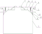
Fig. 1 is a schematic structural diagram of the present invention.
Wherein: 1-distribution box body, 2-upper cover, 3-heat dissipation holes, 4-water baffle, 5-heat dissipation fan, 6-water collection tank, 7-water level detection sensor, 8-drain pipe, 9-valve and 10-slide block.
Detailed Description
In order to deepen the understanding of the present invention, the present invention will be described in detail with reference to the following embodiments, which are only used for explaining the present invention and do not constitute the limitation of the protection scope of the present invention.
As shown in fig. 1, this embodiment provides a synthesize block terminal upper cover waterproof construction, including block terminal box 1 and upper cover 2, upper cover 2 sets up on block terminal box 1, through welded fastening between block terminal box 1 and the upper cover 2, block terminal box 1 and the other ventilation hole 3 that is provided with of 2 junctions of upper cover, dispel the heat in block terminal box 1 through ventilation hole 3, its characterized in that: the water baffle 4 is arranged at the joint of the distribution box body 1 and the upper cover 2, and the water baffle 4 is obliquely arranged and forms an included angle of 30 degrees with the horizontal line. Be provided with radiator fan 5 in the block terminal box 1, lead through radiator fan 5 to the hot-air in the block terminal box 1, blow off hot-air from ventilation hole 3 to open radiator fan 5 in rainy day, produce the windage to ventilation hole 3, prevent that the rainwater from wafting into in the block terminal box 1. The improved rain-proof cover is characterized in that a water collecting tank 6 is arranged on the upper cover 2, a water level detection sensor 7 is arranged in the water collecting tank 6, the water amount in the water collecting tank 6 is detected through the water level detection sensor 7, whether rain falls or not is judged, a drain pipe 8 is arranged at the lower end of the water collecting tank 6, a valve 9 is arranged on the drain pipe 8, the valve 9 is in electrical signal connection with the water level detection sensor 7, and when the water level detection sensor 7 detects that the water level reaches a preset value, the valve 9 is opened. The heat radiation fan 5 is in electric signal connection with a water level detection sensor 7 in the water collection tank 6, and when the water level detection sensor 7 detects that the water level reaches a preset value, the heat radiation fan 5 is started to form a wind resistance. A magnetic sliding block 10 is arranged on the distribution box body 1, and the ventilation holes 3 are shielded through the manual sliding block 10. Install breakwater 4 in 3 inclinations of louvre seted up on upper cover 2, under the great condition of wind and rain, rainwater that will blow into in the box through breakwater 4 blocks, and lead to through radiator fan 5 the hot-air in to block terminal box 1, blow off hot-air from ventilation hole 3, and open radiator fan 5 in rainy day, produce the windage to ventilation hole 3, prevent that the rainwater from wafting into in block terminal box 1, judge whether it is rainy through water level detection sensor 7 in the water catch bowl 6, and accomplish opening of radiator fan 5 automatically, avoid radiator fan to still move and lead to the energy resource consumption to increase when need not the during operation.
Claims (5)
1. The utility model provides a synthesize block terminal upper cover waterproof construction, includes block terminal box (1) and upper cover (2), upper cover (2) set up on block terminal box (1), through welded fastening between block terminal box (1) and upper cover (2), block terminal box (1) and upper cover (2) junction are other to be provided with ventilation hole (3), dispel the heat in block terminal box (1) through ventilation hole (3), its characterized in that: the distribution box is characterized in that a water baffle (4) is arranged at the joint of the distribution box body (1) and the upper cover (2), the water baffle (4) is obliquely arranged and forms an included angle of 30 degrees with a horizontal line.
2. The waterproof structure of the upper cover of the comprehensive distribution box of claim 1, characterized in that: be provided with radiator fan (5) in block terminal box (1), lead through radiator fan (5) to the hot-air in block terminal box (1), blow off hot-air from ventilation hole (3) to open radiator fan (5) in rainy day, produce the windage to ventilation hole (3), prevent that the rainwater from wafting into in block terminal box (1).
3. The waterproof structure of the upper cover of the comprehensive distribution box of claim 1, characterized in that: the rainwater collecting device is characterized in that a water collecting tank (6) is arranged on the upper cover (2), a water level detection sensor (7) is arranged in the water collecting tank (6), the water quantity in the water collecting tank (6) is detected through the water level detection sensor (7), whether rain falls or not is judged, a drain pipe (8) is arranged at the lower end of the water collecting tank (6), a valve (9) is arranged on the drain pipe (8), the valve (9) is in electrical signal connection with the water level detection sensor (7), and the valve (9) is opened to drain water when the water level detection sensor (7) detects that the water level reaches a preset value.
4. The waterproof structure of the upper cover of the comprehensive distribution box of claim 2, characterized in that: the heat dissipation fan (5) is in electrical signal connection with a water level detection sensor (7) in the water collection tank (6), and when the water level detection sensor (7) detects that the water level reaches a preset value, the heat dissipation fan (5) is started to form wind resistance.
5. The waterproof structure of the upper cover of the comprehensive distribution box of claim 1, characterized in that: be provided with on block terminal box (1) and have magnetic slider (10), shield ventilation hole (3) through manual slip slider (10).
Priority Applications (1)
| Application Number | Priority Date | Filing Date | Title |
|---|---|---|---|
| CN201921410126.0U CN210430444U (en) | 2019-08-28 | 2019-08-28 | Synthesize block terminal upper cover waterproof construction |
Applications Claiming Priority (1)
| Application Number | Priority Date | Filing Date | Title |
|---|---|---|---|
| CN201921410126.0U CN210430444U (en) | 2019-08-28 | 2019-08-28 | Synthesize block terminal upper cover waterproof construction |
Publications (1)
| Publication Number | Publication Date |
|---|---|
| CN210430444U true CN210430444U (en) | 2020-04-28 |
Family
ID=70364746
Family Applications (1)
| Application Number | Title | Priority Date | Filing Date |
|---|---|---|---|
| CN201921410126.0U Active CN210430444U (en) | 2019-08-28 | 2019-08-28 | Synthesize block terminal upper cover waterproof construction |
Country Status (1)
| Country | Link |
|---|---|
| CN (1) | CN210430444U (en) |
Cited By (2)
| Publication number | Priority date | Publication date | Assignee | Title |
|---|---|---|---|---|
| CN113054548A (en) * | 2020-12-21 | 2021-06-29 | 国网安徽省电力有限公司淮北供电公司 | Power distribution cabinet with wear-resistant and corrosion-resistant structure |
| CN113725743A (en) * | 2021-09-08 | 2021-11-30 | 芜湖市卓亚电气有限公司 | Box-type substation of european style view box face |
-
2019
- 2019-08-28 CN CN201921410126.0U patent/CN210430444U/en active Active
Cited By (3)
| Publication number | Priority date | Publication date | Assignee | Title |
|---|---|---|---|---|
| CN113054548A (en) * | 2020-12-21 | 2021-06-29 | 国网安徽省电力有限公司淮北供电公司 | Power distribution cabinet with wear-resistant and corrosion-resistant structure |
| CN113054548B (en) * | 2020-12-21 | 2023-02-24 | 国网安徽省电力有限公司淮北供电公司 | Power distribution cabinet with wear-resistant and corrosion-resistant structure |
| CN113725743A (en) * | 2021-09-08 | 2021-11-30 | 芜湖市卓亚电气有限公司 | Box-type substation of european style view box face |
Similar Documents
| Publication | Publication Date | Title |
|---|---|---|
| CN210430444U (en) | Synthesize block terminal upper cover waterproof construction | |
| CN206516951U (en) | A kind of electric automatization power distribution cabinet | |
| CN104863178B (en) | It is placed in the charging device of electric automobile of underground | |
| CN104377574B (en) | A kind of high sensitivity flashing, wind proofing distribution box | |
| CN204407746U (en) | A kind of waterproof and breathable structure of distribution box | |
| CN106374365A (en) | Power distribution box used for motor-pumped well in farmland | |
| CN206004273U (en) | A kind of power cable raceway groove of ventilation and heat | |
| CN104061667A (en) | Waterproof underground structure ventilation opening | |
| CN104377568B (en) | A kind of durable type flashing, wind proofing distribution box | |
| CN206992503U (en) | A kind of outdoor water-proof power distribution cabinet | |
| CN113126677B (en) | Ventilation control system for transformer substation and control method thereof | |
| CN208462276U (en) | A kind of charging pile radiator | |
| CN206695343U (en) | A kind of labyrinth type rainwater-proof fan housing | |
| CN208047069U (en) | A kind of cabinet for the ball machine camera on steel tower | |
| CN208687926U (en) | Blast cap outside new blower intake stack room | |
| CN108598956B (en) | Waterproof and good outdoor regulator cubicle that dispels heat | |
| CN208072881U (en) | A kind of Water-proof exhausting road | |
| CN217300969U (en) | Roof fan | |
| CN206735055U (en) | A kind of good animal train container that radiates | |
| CN202850299U (en) | Electric ventilating skylight | |
| CN202660743U (en) | Anti-freezing device for gas water heater | |
| CN206323694U (en) | Controller housing and controller | |
| CN206829557U (en) | A kind of basement high-efficient ventilation pipeline group | |
| CN205448200U (en) | Rain -proof cover of ventilating air conditioniner pipeline | |
| CN205655935U (en) | " fill " deformation depressor thermometer rain -proof of falling is covered |
Legal Events
| Date | Code | Title | Description |
|---|---|---|---|
| GR01 | Patent grant | ||
| GR01 | Patent grant | ||
| TR01 | Transfer of patent right | ||
| TR01 | Transfer of patent right |
Effective date of registration: 20201207 Address after: 241000 Anhui province Wuhu City Jiuhua Road No. 118 Patentee after: ANHUI XINLONG ELECTRICAL Co.,Ltd. Address before: 241000 Electrical Components Park, Economic and Technological Development Zone, Wuhu City, Anhui Province (118 North Jiuhua Road) Patentee before: ANHUI SINONET & XINLONG SCIENCE & TECHNOLOGY Co.,Ltd. |