CN210392940U - Calcium carbonate powder conveying system - Google Patents
Calcium carbonate powder conveying system Download PDFInfo
- Publication number
- CN210392940U CN210392940U CN201920988169.0U CN201920988169U CN210392940U CN 210392940 U CN210392940 U CN 210392940U CN 201920988169 U CN201920988169 U CN 201920988169U CN 210392940 U CN210392940 U CN 210392940U
- Authority
- CN
- China
- Prior art keywords
- separation
- centrifugal separation
- pipe
- calcium carbonate
- bin
- Prior art date
- Legal status (The legal status is an assumption and is not a legal conclusion. Google has not performed a legal analysis and makes no representation as to the accuracy of the status listed.)
- Active
Links
Images


Abstract
The utility model relates to a calcium carbonate powder conveying system, including air feeder, feedway, air feeder with feedway passes through the conveyer pipe and links to each other with gas-solid separator, and gas-solid separator includes cylindric separation storehouse, is equipped with feed inlet, discharge gate and tail gas export on the separation storehouse, still is equipped with spiral helicine centrifugal separation pipe on the inner wall of separation storehouse, and the position that corresponds with centrifugal separation pipe on the section of thick bamboo wall of separation storehouse is equipped with the powder and overflows the export, and centrifugal separation pipe's inboard is equipped with the gas pocket that overflows. This application is through setting up spiral helicine centrifugal separation pipe on the inner wall in separation storehouse, and powdered material separates under centrifugal action with conveying gas at the intraductal motion in-process of centrifugal separation, and the powdered material that centrifugal separation pipe is close to the section of thick bamboo wall in separation storehouse gets into the storehouse of gathering through powder overflow outlet under centrifugal action, and gas is discharged from the tail gas outlet after getting into the separation storehouse inner chamber through the overflow hole, can be effectively with powder and gas separation, separation efficiency is high.
Description
Technical Field
The utility model relates to a calcium carbonate production facility, especially a calcium carbonate powder conveying system.
Background
Light Calcium Carbonate (Light Calcium Carbonate), also known as Precipitated Calcium Carbonate (PCC), is produced by chemical processing and is called Light Calcium Carbonate because its sedimentation volume (2.4-2.8mL/g) is greater than that of mechanically produced heavy Calcium Carbonate (1.1-1.9 mL/g); the production process includes burning limestone and other material to produce lime and carbon dioxide, adding water to slake lime to produce lime milk, carbonizing lime milk with carbon dioxide to produce calcium carbonate precipitate, dewatering, drying and crushing.
The light calcium carbonate is prepared and then conveyed to a storage bin through a pipeline, and at present, a plurality of powder airflow conveying systems are adopted, for example, a light calcium carbonate powder airflow conveying system disclosed by the publication number of CN206857730U comprises an air supply device, a feeding device, a gas-solid separation device, a discharging device and an automatic controller, and the disclosed technical scheme can effectively avoid pipeline blockage; however, the gas-solid separation device in the document has low separation efficiency, and the dust remover has a simple structure and poor dust removal effect, and needs to be improved urgently.
SUMMERY OF THE UTILITY MODEL
An object of the utility model is to provide a calcium carbonate powder conveying system for solve the problem that current calcium carbonate powder conveying system gas-solid separation efficiency is low.
In order to solve the problems, the utility model provides a calcium carbonate powder conveying system, including air feeder, feedway, air feeder with feedway links to each other with gas-solid separator through the conveyer pipe, gas-solid separator includes cylindric separation storehouse, be equipped with feed inlet, discharge gate and tail gas export on the separation storehouse, still be equipped with on the inner wall in separation storehouse with the feed inlet with the spiral helicine centrifugal separation pipe that the discharge gate links to each other, the position that corresponds with the centrifugal separation pipe on the section of thick bamboo wall in separation storehouse is equipped with the powder overflow mouth, the inboard of centrifugal separation pipe is equipped with the gas overflow mouth; a collecting bin is further arranged on the outer side of the separation bin, and the collecting bin is communicated with the centrifugal separation pipe through the powder overflow outlet; the discharge port is connected with the feed bin through a pipeline, and the tail gas outlet is also connected with a dust removal device.
The utility model provides a calcium carbonate powder conveying system still has following technical characteristic:
further, the feed inlet sets up on the lateral wall that the separation bin is close to the top, the discharge gate sets up on the separation bin bottom plate, the tail gas export sets up on the roof of separation bin.
Furthermore, the section of the centrifugal separation tube is semicircular, and the diameter section of the semicircular ring is attached to the inner surface of the side wall of the separation bin.
Furthermore, the powder overflow outlet is formed in the position, corresponding to the diameter section of the centrifugal separation pipe, of the cylinder wall of the separation bin, and is located at the bottom of the diameter section of the centrifugal separation pipe.
Further, the height of the powder overflow port in the vertical direction is greater than or equal to one tenth of the inner diameter of the centrifugal separation pipe and less than or equal to one third of the inner diameter of the centrifugal separation pipe.
Furthermore, the powder overflow outlet is continuously arranged on the side wall of the separation bin in the collection bin to form a spiral powder overflow outlet corresponding to the centrifugal separation tube.
Further, the air overflow holes are round holes and are arranged on the inner side pipe wall of the centrifugal separation pipe at intervals.
Further, on the semicircular ring-shaped section of the centrifugal separation pipe, the height of the air overflow hole is greater than the height of the circle center of the semicircular ring.
Further, the helix angle of the centrifugal separation tube is 10 ° or more and 45 ° or less.
Further, the helix angle of the centrifuge tube is equal to 15 ° or 20 °.
The utility model discloses following beneficial effect has: powdery materials in the feeding device enter the separation bin through the conveying pipe under the action of the gas supply device, the spiral centrifugal separation pipe is arranged on the inner wall of the separation bin, the powdery materials and the conveying gas are separated under the centrifugal action in the movement process of the centrifugal separation pipe, the powdery materials on the wall, close to the separation bin, of the centrifugal separation pipe enter the gathering bin through the powder overflow outlet under the centrifugal action, and the gas enters the inner cavity of the separation bin through the overflow hole and then is discharged from the tail gas outlet, so that the powder and the gas can be effectively separated, and the separation efficiency is high; the dust content of the separated gas is less, and the load of the dust removal device can be effectively relieved.
Drawings
Fig. 1 is a schematic structural diagram of a calcium carbonate powder conveying system according to an embodiment of the present invention;
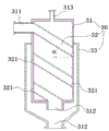
FIG. 2 is a schematic structural diagram of a gas-solid separation device in an embodiment of the present invention;
fig. 3 is a schematic structural diagram of a gas-solid separation device in an embodiment of the present invention;
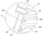
fig. 4 is a partially enlarged view of a portion a in fig. 3.
Detailed Description
The present invention will be described in detail below with reference to the accompanying drawings in conjunction with embodiments. It should be noted that, in the present invention, the embodiments and features of the embodiments may be combined with each other without conflict.
As shown in fig. 1 to 4, in an embodiment of the calcium carbonate powder conveying system of the present invention, the calcium carbonate powder conveying system includes an air supply device 10 and a feeding device 20, the air supply device 10 and the feeding device 20 are connected to a gas-solid separation device 30 through a conveying pipe, the gas-solid separation device 30 includes a cylindrical separation chamber 31, the separation chamber 31 is provided with a feeding port 311, a discharging port 312 and a tail gas outlet 313, the inner wall of the separation chamber 31 is further provided with a spiral centrifugal separation pipe 32 connected to the feeding port 311 and the discharging port 312, a powder overflow port 321 is provided at a position corresponding to the centrifugal separation pipe 32 on the wall of the separation chamber 31, and an overflow hole 322 is provided at the inner side of the centrifugal separation pipe 32; the outer side of the separation bin 31 is also provided with a collection bin 33, and the collection bin 33 is communicated with the centrifugal separation pipe 32 through a powder overflow port 321; the discharge port 312 is connected with the storage bin 40 through a pipeline, and the tail gas outlet 313 is also connected with the dust removal device 50. In the application, the powdery material in the feeding device enters the separation bin through the conveying pipe under the action of the gas supply device, the spiral centrifugal separation pipe is arranged on the inner wall of the separation bin, the powdery material and the conveying gas are separated under the centrifugal action in the movement process in the centrifugal separation pipe, the powdery material on the wall, close to the separation bin, of the centrifugal separation pipe enters the gathering bin through the powder overflow outlet under the centrifugal action, and the gas enters the inner cavity of the separation bin through the overflow hole and then is discharged from the tail gas outlet, so that the powder and the gas can be effectively separated, and the separation efficiency is high; the dust content of the separated gas is less, and the load of the dust removal device can be effectively relieved.
In the above embodiment, the air supply device 10 may be a blower, and a dryer may be disposed at an air outlet of the blower; the feeding device 20 reports and considers a buffer bin 21, an impeller is a feeding cavity 22, an impeller 23 and the like; in one embodiment of the present application, the dust removing device 50 includes a dust removing tank 51, an aqueous solution for removing dust is filled in the dust removing tank 51, an air inlet 52 is arranged at the lower part of the dust removing tank 51, a filter screen 53 is further fixed at a position higher than the liquid level in the dust removing tank 51, a spray nozzle 54 for spraying water drops to the upper surface of the filter screen 53 is further fixed on the inner wall of the dust removing tank 51, and the filter screen and the water spray are matched to further remove dust; in this embodiment, the gas inlet 52 may be further provided with a backflow-preventing check valve, and the dust removing tank 51 may be further provided with a gas distribution pipeline therein so that the gas from the gas inlet 52 entering the dust removing tank 51 is uniformly distributed in the aqueous solution to filter dust particles in the gas through the aqueous solution.
In one embodiment of the present application, preferably, the feeding port 311 is disposed on the sidewall of the separation chamber 31 near the top, the discharging port 312 is disposed on the bottom plate of the separation chamber 31, and the tail gas outlet 313 is disposed on the top plate of the separation chamber 31, so that the gas-solid mixture can be accelerated by the gravity of the solid powder when moving in the centrifugal separation tube 32 to improve the centrifugal separation effect.
In one embodiment of the present application, as shown in fig. 3 and 4, the section of the centrifugal separation tube 32 is preferably semicircular, and the diameter section of the semicircular ring is attached to the inner surface of the side wall of the separation chamber 31, so that the outer wall of the centrifugal separation tube has a larger contact area with the separation chamber, which can improve the centrifugal separation effect. Preferably, a powder overflow outlet 321 is opened on the wall of the separation bin 31 at a position corresponding to the diameter section of the centrifugal separation tube 32, and the powder overflow outlet 321 is located at the bottom of the diameter section of the centrifugal separation tube 32, so that the powder solid can fall down along the inner wall of the separation bin and enter the collection bin 33 through the powder overflow outlet 321. Preferably, the height of the powder overflow port 321 in the vertical direction is greater than or equal to one tenth of the inner diameter of the centrifugal separation tube 32 and less than or equal to one third of the inner diameter of the centrifugal separation tube 32, so that the dust particles can be collected at the upper part of the diameter section of the centrifugal separation tube by centrifugal action and then enter the collection bin 33 through the powder overflow port 321 under the action of gravity, it can be understood that, in the process of the upward and downward rotating motion of the gas-solid mixture in the spiral centrifugal separation tube 32, the powder particles after centrifugal separation are collected to the collection bin 33 through the powder overflow ports 321 on different tube sections, continuous centrifugal separation can be realized, and the gas and solid powder can be completely separated before the gas-solid mixture reaches the discharge port 312 on the separation bin 31. Preferably, the powder overflow port 321 is continuously opened on the sidewall of the separation chamber 31 located in the collection chamber 33 to form a spiral powder overflow port 321 corresponding to the centrifugal separation tube 32.
In one embodiment of the present application, as shown in fig. 3 and 4, it is preferable that the overflow holes 322 are circular holes and are arranged at intervals on the inner wall of the centrifugal separation tube 32, and it is preferable that the height of the overflow holes 322 is greater than the height of the center of the semicircular ring on the semicircular ring-shaped cross section of the centrifugal separation tube 32, so that the gas after gas-solid separation can be smoothly discharged from the centrifugal separation tube, and it is preferable that the helix angle α of the centrifugal separation tube is greater than or equal to 10 ° and less than or equal to 45 °, so that the gas and powder can be sufficiently separated from the gas by centrifugal action when being fixed in the centrifugal separation tube, and it is preferable that the helix angle α of the centrifugal separation tube is equal to 15 ° or 20 °.
Finally, it should be noted that: the above embodiments are only used to illustrate the technical solution of the present invention, and not to limit it; although the present invention has been described in detail with reference to the foregoing embodiments, it should be understood by those skilled in the art that: the technical solutions described in the foregoing embodiments may still be modified, or some technical features may be equivalently replaced; such modifications and substitutions do not depart from the spirit and scope of the present invention in its corresponding aspects.
Claims (10)
1. A calcium carbonate powder conveying system comprises a gas supply device and a feeding device, wherein the gas supply device and the feeding device are connected with a gas-solid separation device through a conveying pipe, and the calcium carbonate powder conveying system is characterized in that the gas-solid separation device comprises a cylindrical separation bin, a feed inlet, a discharge outlet and a tail gas outlet are arranged on the separation bin, a spiral centrifugal separation pipe connected with the feed inlet and the discharge outlet is further arranged on the inner wall of the separation bin, a powder overflow outlet is arranged at a position, corresponding to the centrifugal separation pipe, on the wall of the separation bin, and an overflow hole is formed in the inner side of the centrifugal separation pipe; a collecting bin is further arranged on the outer side of the separation bin, and the collecting bin is communicated with the centrifugal separation pipe through the powder overflow outlet; the discharge port is connected with the feed bin through a pipeline, and the tail gas outlet is also connected with a dust removal device.
2. The calcium carbonate powder conveying system according to claim 1, characterized in that: the feed inlet sets up on the lateral wall that the separation bin is close to the top, the discharge gate sets up on the separation bin bottom plate, the tail gas export sets up on the roof of separation bin.
3. The calcium carbonate powder conveying system according to claim 1, characterized in that: the section of the centrifugal separation pipe is semicircular, and the diameter section of the semicircular ring is attached to the inner surface of the side wall of the separation bin.
4. The calcium carbonate powder conveying system according to claim 3, characterized in that: the powder overflow outlet is formed in the position, corresponding to the diameter section of the centrifugal separation pipe, of the cylinder wall of the separation bin, and is located at the bottom of the diameter section of the centrifugal separation pipe.
5. The calcium carbonate powder conveying system according to claim 4, characterized in that: the height of the powder overflow port in the vertical direction is more than or equal to one tenth of the inner diameter of the centrifugal separation pipe and less than or equal to one third of the inner diameter of the centrifugal separation pipe.
6. The calcium carbonate powder conveying system according to claim 5, characterized in that: the powder overflow port is continuously arranged on the side wall of the separation bin in the collection bin to form a spiral powder overflow port corresponding to the centrifugal separation tube.
7. The calcium carbonate powder conveying system according to claim 6, characterized in that: the air overflow holes are round holes and are arranged on the inner side pipe wall of the centrifugal separation pipe at intervals.
8. The calcium carbonate powder conveying system according to claim 7, characterized in that: on the semicircular ring-shaped section of the centrifugal separation pipe, the height of the air overflow hole is greater than the height of the circle center of the semicircular ring.
9. The calcium carbonate powder conveying system according to claim 1, characterized in that: the helix angle of the centrifugal separation tube is greater than or equal to 10 degrees and less than or equal to 45 degrees.
10. The calcium carbonate powder conveying system according to claim 9, characterized in that: the helix angle of the centrifuge tube is equal to 15 ° or 20 °.
Priority Applications (1)
| Application Number | Priority Date | Filing Date | Title |
|---|---|---|---|
| CN201920988169.0U CN210392940U (en) | 2019-06-28 | 2019-06-28 | Calcium carbonate powder conveying system |
Applications Claiming Priority (1)
| Application Number | Priority Date | Filing Date | Title |
|---|---|---|---|
| CN201920988169.0U CN210392940U (en) | 2019-06-28 | 2019-06-28 | Calcium carbonate powder conveying system |
Publications (1)
| Publication Number | Publication Date |
|---|---|
| CN210392940U true CN210392940U (en) | 2020-04-24 |
Family
ID=70351344
Family Applications (1)
| Application Number | Title | Priority Date | Filing Date |
|---|---|---|---|
| CN201920988169.0U Active CN210392940U (en) | 2019-06-28 | 2019-06-28 | Calcium carbonate powder conveying system |
Country Status (1)
| Country | Link |
|---|---|
| CN (1) | CN210392940U (en) |
Cited By (2)
| Publication number | Priority date | Publication date | Assignee | Title |
|---|---|---|---|---|
| CN112722864A (en) * | 2020-12-24 | 2021-04-30 | 创志科技(江苏)股份有限公司 | Material conveying and exhausting mechanism and working method thereof |
| CN116177228A (en) * | 2023-03-15 | 2023-05-30 | 湖南可达粉粒输送环保科技有限公司 | Discharging device for pneumatic conveying |
-
2019
- 2019-06-28 CN CN201920988169.0U patent/CN210392940U/en active Active
Cited By (3)
| Publication number | Priority date | Publication date | Assignee | Title |
|---|---|---|---|---|
| CN112722864A (en) * | 2020-12-24 | 2021-04-30 | 创志科技(江苏)股份有限公司 | Material conveying and exhausting mechanism and working method thereof |
| CN116177228A (en) * | 2023-03-15 | 2023-05-30 | 湖南可达粉粒输送环保科技有限公司 | Discharging device for pneumatic conveying |
| CN116177228B (en) * | 2023-03-15 | 2023-09-29 | 湖南可达粉粒输送环保科技有限公司 | Discharging device for pneumatic conveying |
Similar Documents
| Publication | Publication Date | Title |
|---|---|---|
| CN100406142C (en) | Separating method and separator | |
| CN210392940U (en) | Calcium carbonate powder conveying system | |
| CN104399607B (en) | A kind of cyclone separator and the cyclone separation system based on the device | |
| CN104176503A (en) | Gap-discharging continuous vacuum feeding machine | |
| CN203269080U (en) | Row type continuous type vacuum charging device | |
| CN203578034U (en) | Cyclone separator | |
| CN103272776A (en) | Wind pressure type three-cabin wind separator | |
| CN109626014A (en) | Husk cleaning, storage and conveying production line | |
| CN114272744A (en) | Moving bed device and process for dry flue gas desulfurization | |
| CN204469407U (en) | A kind of gas-solid separating device for powder material loading | |
| CN107694229A (en) | A kind of sack cleaner with dust processing | |
| CN208166073U (en) | A kind of reduced titanium iron powder calcination rotary kiln blanking device | |
| CN206857730U (en) | A kind of precipitated calcium carbonate powder flow delivery systems | |
| CN107416373B (en) | A kind of incineration of refuse flyash automatic storage unloads grey library | |
| CN206027607U (en) | Feed mixer raw materials conveying system | |
| CN209554367U (en) | Husk cleaning, storage and conveying production line | |
| CN209010153U (en) | A kind of fine powder sulphuring treatment system in wet-method sulfur forming device | |
| CN209524730U (en) | A kind of production biomass fuel drying equipment | |
| CN204469917U (en) | A kind of cyclone dust collectors | |
| CN208928526U (en) | Screening plant is used in a kind of production of desulfurizing agent | |
| CN110538728A (en) | Cyclone powder separator | |
| CN106492966A (en) | Waste electric wire cable automatization cracking and sorting system | |
| CN207973233U (en) | A kind of bulk material conveying equipment | |
| CN202199430U (en) | Internal cycle type fly ash flotation separation device | |
| CN210700672U (en) | Cyclone powder separator |
Legal Events
| Date | Code | Title | Description |
|---|---|---|---|
| GR01 | Patent grant | ||
| GR01 | Patent grant |