CN210356759U - Agitating unit is used in production of petroleum auxiliary agent - Google Patents
Agitating unit is used in production of petroleum auxiliary agent Download PDFInfo
- Publication number
- CN210356759U CN210356759U CN201921142552.0U CN201921142552U CN210356759U CN 210356759 U CN210356759 U CN 210356759U CN 201921142552 U CN201921142552 U CN 201921142552U CN 210356759 U CN210356759 U CN 210356759U
- Authority
- CN
- China
- Prior art keywords
- wall
- main part
- conveyer
- connecting rod
- connecting seat
- Prior art date
- Legal status (The legal status is an assumption and is not a legal conclusion. Google has not performed a legal analysis and makes no representation as to the accuracy of the status listed.)
- Expired - Fee Related
Links
Images


Landscapes
- Mixers Of The Rotary Stirring Type (AREA)
Abstract
The utility model discloses an agitating unit is used in production of oil auxiliary agent, including main part and conveying mechanism, the bottom activity of main part is provided with the supporting seat, and the top right side of main part settles and have the feed inlet, the conveying mechanism activity sets up in the outer wall left side of feed inlet, the outer wall inboard of main part is settled there is the water inlet, and the below of water inlet is provided with power unit. This agitating unit is used in petroleum auxiliary production is provided with the main part, be swing joint between conveyer and the main part, when making the conveyer use in the device for a long time, if the unable normal operating that breaks down, user's accessible bolt is demolishd the conveyer from the device in, the trouble part in the conveyer is maintained, change, improve the maintenance ageing of part in the device, the conveyer passes through roller train and bull stick constitution revolution mechanic simultaneously, the user is when the user is the operative installations, start the motor of conveyer adaptation, it is rotatory to make the motor drive roller train, the roller train drives the bull stick rotation.
Description
Technical Field
The utility model relates to a agitating unit technical field for the petroleum auxiliary agent specifically is an agitating unit is used in petroleum auxiliary agent production.
Background
With the rapid development of economy and the advancement of science and technology in various regions, the petroleum auxiliary agent is a powdery product which is formed by compounding a plurality of natural fibers, filling particles and additives which are treated by special processes according to proper gradation and a certain process, after the product is added in a well, under the action of unidirectional pressure difference, the product can play a good role in blocking various leakages in the stratum, is convenient to use, has good compatibility, does not influence the performance of slurry, and needs to stir raw materials during production so that the plurality of raw materials are mixed with one another, and at the moment, a professional stirring device is needed for auxiliary operation.
Stirring apparatus for petroleum auxiliary in market does not possess and carries out the automation to the raw materials in the use for the raw materials needs the manual work to carry the raw materials when the access to plant, reduces device availability factor, and be unfavorable for device large capacity long-term operation, interval between the stirring piece in the unable adjusting device, makes the device can not be according to the characteristic of different raw materialss, free adjusting device stirring angle, reduction device use flexibility, for this reason, we propose a stirring apparatus for the production of petroleum auxiliary.
SUMMERY OF THE UTILITY MODEL
An object of the utility model is to provide an agitating unit is used in production of oil auxiliary agent, with the agitating unit is used to the oil auxiliary agent who proposes in solving above-mentioned background art in the use, do not possess and carry out the automation to the raw materials and carry, make the raw materials when the access arrangement, need artifically carry the raw materials, reducing mechanism availability factor, and be unfavorable for device large capacity long-term operation, interval between the stirring piece in the unable adjusting device, make the device can not be according to the characteristic of different raw materialss, free adjusting device stirring angle, the problem that the reducing mechanism used the flexibility.
In order to achieve the above object, the utility model provides a following technical scheme: the utility model provides an agitating unit is used in production of petroleum auxiliary agent, includes main part and conveying mechanism, the bottom activity of main part is provided with the supporting seat, and the top right side of main part settles and have the feed inlet, conveying mechanism activity sets up in the outer wall left side of feed inlet, the outer wall inboard of main part settles and have the water inlet, and the below of water inlet is provided with power unit, power unit's outer wall one side activity is settled and is had the moving mechanism, the bottom of main part is connected with the discharge gate.
Preferably, the conveying mechanism comprises a conveyor, a roller set, a rotating rod and a crawler, the roller set is arranged in the conveyor, the rotating rod is arranged on the outer wall of the roller set, and the crawler is movably arranged on the outer wall of the rotating rod.
Preferably, the conveyer is movably connected with the main body, and the conveyer and the rotating rod form a rotating structure through a roller set.
Preferably, the power mechanism comprises a transverse plate, a motor, a driving gear, a driven gear, a connecting rod and an outer joint, the motor is arranged at the top of the transverse plate, the driving gear is arranged on one side of the motor, the driven gear is movably arranged on the outer wall of the driving gear, the connecting rod is arranged on the right side of the outer wall of the driven gear, and the outer joint is arranged at the other end of the connecting rod.
Preferably, the connecting rod is fixedly connected with the outer joint, and the connecting rod forms an engaging structure with the driving gear through the driven gear.
Preferably, the movable mechanism comprises a connector, a rotating shaft, a connecting seat, a stirring sheet and a fixed bearing, wherein the rotating shaft is arranged at one end of the outer wall of the connector, the connecting seat is movably arranged on the outer wall of the rotating shaft, the stirring sheet is arranged at the top of the connecting seat, the fixed bearing is arranged at the other end of the outer wall of the rotating shaft, the rotating shaft is movably connected with the connecting seat, and the connecting seat is welded with the stirring sheet.
Compared with the prior art, the beneficial effects of the utility model are that: the stirring device for producing the petroleum auxiliary agent is provided with the main body, the conveyer and the main body are movably connected, so that when the conveyer is used in the device for a long time, if the conveyer fails to normally run, a user can remove the conveyer from the device through bolts to maintain and replace the failed parts in the conveyer, the maintenance timeliness of the parts in the device is improved, meanwhile, the conveyer and the rotating rod form a rotating structure through the roller train, and when the user uses the device, the motor matched with the conveyer is started, so that the motor drives the roller train to rotate, the roller train drives the rotating rod to rotate, the rotating rod drives the track to rotate, various raw materials can be conveyed through the conveyer, the use efficiency of the device is improved, and the labor intensity of workers is reduced;
the connecting rod is fixedly connected with the outer joint, so that when the connecting rod works, the outer joint can be always connected onto the connecting rod in a high-strength connection manner, the connection strength between the outer joint and the connecting rod is improved, the outer joint is prevented from falling off from the connecting rod when the connecting rod works, meanwhile, the connecting rod forms a meshing structure with the driving gear through the driven gear, so that when equipment in the device works, the driving gear on the motor can reduce the speed through the driven gear, the reasonable working rotating speed of stirring of the device is achieved, the stirring efficiency of the device on raw materials is improved, and the service life of corresponding parts in the device can be indirectly protected;
be swing joint between pivot and the connecting seat, the user can adjust the connecting seat in the epaxial interval of commentaries on classics wantonly, adjust the connecting seat, the device of being convenient for is according to the characteristic of different materials, adjusting device's stirring angle, improve device use flexibility, increase the device utilization ratio, connected mode between connecting seat and the stirring piece is the welding simultaneously, make can not appear the crack between stirring piece and the connecting seat, improve the connection leakproofness of stirring piece and connecting seat, be provided with the strip through-hole on the stirring piece, make the stirring piece when rotating, the through-hole of multiple material accessible stirring piece mixes, make the device stirring effect more even.
Drawings
FIG. 1 is a schematic structural view of the present invention;
FIG. 2 is a schematic view of the driven gear of the present invention;
fig. 3 is an enlarged schematic view of a portion a in fig. 1 according to the present invention.
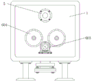
In the figure: 1. a main body; 2. a supporting seat; 3. a feed inlet; 4. a conveying mechanism; 401. a conveyor; 402. a roller set; 403. a rotating rod; 404. a crawler belt; 5. a water inlet; 6. a power mechanism; 601. a transverse plate; 602. a motor; 603. a driving gear; 604. a driven gear; 605. a connecting rod; 606. an outer joint; 7. a movable mechanism; 701. a connector; 702. a rotating shaft; 703. a connecting seat; 704. a stirring sheet; 705. fixing the bearing; 8. and (4) a discharge port.
Detailed Description
The technical solutions in the embodiments of the present invention will be described clearly and completely with reference to the accompanying drawings in the embodiments of the present invention, and it is obvious that the described embodiments are only some embodiments of the present invention, not all embodiments. Based on the embodiments in the present invention, all other embodiments obtained by a person skilled in the art without creative work belong to the protection scope of the present invention.
Referring to fig. 1-3, the present invention provides a technical solution: a stirring device for petroleum additive production comprises a main body 1 and a conveying mechanism 4, wherein a supporting seat 2 is movably arranged at the bottom of the main body 1, a feeding hole 3 is formed in the right side of the top of the main body 1, the conveying mechanism 4 is movably arranged on the left side of the outer wall of the feeding hole 3, the conveying mechanism 4 comprises a conveyor 401, a roller set 402, a rotating rod 403 and a crawler belt 404, the roller set 402 is arranged inside the conveyor 401, the rotating rod 403 is arranged on the outer wall of the roller set 402, the crawler belt 404 is movably arranged on the outer wall of the rotating rod 403, so that when the conveyor 401 is used in the device for a long time and fails to normally, a user can remove the conveyor 401 from the device through bolts, repair and replace the fault parts in the conveyor 401, the repair timeliness of the parts in the device is improved, the conveyor 401 is movably connected with the main body 1, and the conveyor 401 and the rotating rod 403 form a rotating structure through the, when a user uses the device, the motor matched with the conveyor 401 is started, so that the motor drives the roller set 402 to rotate, the roller set 402 drives the rotating rod 403 to rotate, the rotating rod 403 drives the crawler belt 404 to rotate, various raw materials can be conveyed through the conveyor 401, the use efficiency of the device is improved, and the labor intensity of workers is reduced;
the inner side of the outer wall of the main body 1 is provided with a water inlet 5, a power mechanism 6 is arranged below the water inlet 5, the power mechanism 6 comprises a transverse plate 601, a motor 602, a driving gear 603, a driven gear 604, a connecting rod 605 and an external joint 606, the top of the transverse plate 601 is provided with the motor 602, one side of the motor 602 is provided with the driving gear 603, the outer wall of the driving gear 603 is movably provided with the driven gear 604, the right side of the outer wall of the driven gear 604 is provided with the connecting rod 605, the other end of the connecting rod 605 is provided with the external joint 606, so that when the connecting rod 605 works, the external joint 606 can be always connected to the connecting rod 605 in a high-strength connection manner, the connection strength between the external joint 606 and the connecting rod 605 is improved, the external joint 606 is prevented from falling off from the connecting rod 605 when the connecting rod 605 works, when equipment in the device runs, the driving gear 603 on the motor 602 can reduce the speed through the driven gear 604, so that the reasonable working speed of the device for stirring is achieved, the stirring efficiency of the device for raw materials is improved, and the service lives of corresponding parts in the device can be indirectly protected;
a movable mechanism 7 is movably arranged on one side of the outer wall of the power mechanism 6, the movable mechanism 7 comprises a connector 701, a rotating shaft 702, a connecting seat 703, a stirring sheet 704 and a fixed bearing 705, the rotating shaft 702 is arranged at one end of the outer wall of the connector 701, the connecting seat 703 is movably arranged on the outer wall of the rotating shaft 702, the stirring sheet 704 is arranged at the top of the connecting seat 703, the fixed bearing 705 is arranged at the other end of the outer wall of the rotating shaft 702, the rotating shaft 702 is movably connected with the connecting seat 703, the connecting seat 703 and the stirring sheet 704 are connected in a welding mode, a user can freely adjust the distance between the connecting seat 703 and the rotating shaft 702 to adjust the connecting seat 703, the device is convenient to adjust the stirring angle of the device according to the characteristics of different materials, the use flexibility.
The working principle is as follows: for the stirring device for petroleum additives, firstly, after a user moves the device to any place needing to be used, a supporting seat 2 is contacted with a ground foundation, the device is supported, the device is prevented from shaking in use, the user places a plurality of raw materials needing to be used in the production of the petroleum additives on a crawler belt 404, a motor matched with a conveyor 401 is started, the motor drives a roller set 402 to rotate, after the roller set 402 drives a rotating rod 403 to rotate, the crawler belt 404 synchronously rotates, the raw materials are automatically conveyed to a feed inlet 3, so that the raw materials enter the device from the feed inlet 3, the user starts a motor 602 (model: Y90S-2) on a transverse plate 601, the motor 602 drives a driving gear 603 to rotate, after the driving gear 603 drives a driven gear 604 to rotate, the driven gear 604 drives a connecting rod 605 to rotate, the connecting rod 605 drives an external joint 606 to rotate, external joint 606 drives connector 701 rotatory back, the corresponding rotation of pivot 702 of connector 701 one side, make stirring piece 704 fast revolution on the connecting seat 703 in pivot 702, stir the operation to the raw materials, one side of pivot 702 is provided with fixing bearing 705, make fixing bearing 705 can rotate spacing supplementary to pivot 702, the back is accomplished in the stirring, the user can connect collecting device on discharge gate 8, valve on through discharge gate 8, discharge the material from the device in, when the device is inside to be washd, the user can be with external water piping connection on water inlet 5, make in the liquid access device, convenient to use person's later stage belt cleaning device.
Although embodiments of the present invention have been shown and described, it will be appreciated by those skilled in the art that changes, modifications, substitutions and alterations can be made in these embodiments without departing from the principles and spirit of the invention, the scope of which is defined in the appended claims and their equivalents.
Claims (6)
1. The utility model provides an agitating unit is used in production of petroleum auxiliary agent, includes main part (1) and conveying mechanism (4), its characterized in that: the bottom activity of main part (1) is provided with supporting seat (2), and the top right side of main part (1) settles and have feed inlet (3), conveying mechanism (4) activity sets up in the outer wall left side of feed inlet (3), the outer wall inboard of main part (1) settles and have water inlet (5), and the below of water inlet (5) is provided with power unit (6), the activity of outer wall one side of power unit (6) settles and have moving mechanism (7), the bottom of main part (1) is connected with discharge gate (8).
2. The stirring device for petroleum additive production according to claim 1, characterized in that: the conveying mechanism (4) comprises a conveyor (401), a roller set (402), a rotating rod (403) and a crawler (404), wherein the roller set (402) is arranged inside the conveyor (401), the rotating rod (403) is arranged on the outer wall of the roller set (402), and the crawler (404) is movably arranged on the outer wall of the rotating rod (403).
3. The stirring device for petroleum additive production according to claim 2, characterized in that: the conveyer (401) is movably connected with the main body (1), and the conveyer (401) forms a rotating structure with the rotating rod (403) through the roller group (402).
4. The stirring device for petroleum additive production according to claim 1, characterized in that: the power mechanism (6) comprises a transverse plate (601), a motor (602), a driving gear (603), a driven gear (604), a connecting rod (605) and an outer joint (606), wherein the motor (602) is arranged at the top of the transverse plate (601), the driving gear (603) is arranged on one side of the motor (602), the driven gear (604) is movably arranged on the outer wall of the driving gear (603), the connecting rod (605) is arranged on the right side of the outer wall of the driven gear (604), and the outer joint (606) is arranged at the other end of the connecting rod (605).
5. The stirring device for producing petroleum additives as claimed in claim 4, wherein: the connecting rod (605) is fixedly connected with the outer joint (606), and the connecting rod (605) and the driving gear (603) form a meshing structure through the driven gear (604).
6. The stirring device for petroleum additive production according to claim 1, characterized in that: the movable mechanism (7) comprises a connector (701), a rotating shaft (702), a connecting seat (703), a stirring sheet (704) and a fixed bearing (705), wherein the rotating shaft (702) is arranged at one end of the outer wall of the connector (701), the connecting seat (703) is movably arranged on the outer wall of the rotating shaft (702), the stirring sheet (704) is arranged at the top of the connecting seat (703), the fixed bearing (705) is arranged at the other end of the outer wall of the rotating shaft (702), the rotating shaft (702) is movably connected with the connecting seat (703), and the connecting seat (703) is connected with the stirring sheet (704) in a welding mode.
Priority Applications (1)
| Application Number | Priority Date | Filing Date | Title |
|---|---|---|---|
| CN201921142552.0U CN210356759U (en) | 2019-07-20 | 2019-07-20 | Agitating unit is used in production of petroleum auxiliary agent |
Applications Claiming Priority (1)
| Application Number | Priority Date | Filing Date | Title |
|---|---|---|---|
| CN201921142552.0U CN210356759U (en) | 2019-07-20 | 2019-07-20 | Agitating unit is used in production of petroleum auxiliary agent |
Publications (1)
| Publication Number | Publication Date |
|---|---|
| CN210356759U true CN210356759U (en) | 2020-04-21 |
Family
ID=70272805
Family Applications (1)
| Application Number | Title | Priority Date | Filing Date |
|---|---|---|---|
| CN201921142552.0U Expired - Fee Related CN210356759U (en) | 2019-07-20 | 2019-07-20 | Agitating unit is used in production of petroleum auxiliary agent |
Country Status (1)
| Country | Link |
|---|---|
| CN (1) | CN210356759U (en) |
Cited By (1)
| Publication number | Priority date | Publication date | Assignee | Title |
|---|---|---|---|---|
| CN113083090A (en) * | 2021-04-09 | 2021-07-09 | 周树东 | Nutrient soil preparation equipment suitable for assembly line operation |
-
2019
- 2019-07-20 CN CN201921142552.0U patent/CN210356759U/en not_active Expired - Fee Related
Cited By (1)
| Publication number | Priority date | Publication date | Assignee | Title |
|---|---|---|---|---|
| CN113083090A (en) * | 2021-04-09 | 2021-07-09 | 周树东 | Nutrient soil preparation equipment suitable for assembly line operation |
Similar Documents
| Publication | Publication Date | Title |
|---|---|---|
| CN111927054B (en) | Mortar spraying device with gradually-changed spraying direction | |
| CN214076271U (en) | Avoid mixing arrangement for lubricating oil production of lubricating oil adhesion inner wall | |
| CN210356759U (en) | Agitating unit is used in production of petroleum auxiliary agent | |
| CN206597744U (en) | A kind of nonmetallic ore New Cycle water log washer | |
| CN216726637U (en) | Special preparation facilities of boiler flue gas desulfurization tower restoration agent | |
| CN220195478U (en) | Mixing screening machine | |
| CN203975862U (en) | A kind of belt cleaning device and there is its belt transporter | |
| CN207126458U (en) | Surface coating dosing apparatus is used in a kind of fire hose production | |
| CN206589144U (en) | A kind of build concrete agitating device | |
| CN206635848U (en) | A kind of tank mud equipment for harbour machinery | |
| CN206778319U (en) | A kind of efficient chemical industry mixer | |
| CN110975694A (en) | Pulping device for modified starch processing | |
| CN211566457U (en) | Cement remediation's accelerator ration pumping installations | |
| CN206139126U (en) | Secondary flour mixer | |
| CN114524292A (en) | Sour feeding device is mixed to rotation type | |
| CN208247177U (en) | One kind back and forth stirring vertical agitating device for building | |
| CN2775202Y (en) | Lifting device for automatic wall plastering machine hopper | |
| CN201423260Y (en) | A new type high-efficiency energy-saving planetary vacuum mixer | |
| CN211246350U (en) | Device for adding wet and fresh fermented soybean meal into feed | |
| CN207844545U (en) | A kind of waste material crushing conveyor | |
| CN111438819A (en) | Vertical concrete mixing device | |
| CN207105278U (en) | A kind of efficiently mixer for building | |
| CN205870989U (en) | A production line for polyvinyl chloride waterproof coil | |
| CN110813861A (en) | Efficient ore washing equipment | |
| CN206780682U (en) | A kind of mortar pump mortar feeding device |
Legal Events
| Date | Code | Title | Description |
|---|---|---|---|
| GR01 | Patent grant | ||
| GR01 | Patent grant | ||
| CF01 | Termination of patent right due to non-payment of annual fee |
Granted publication date: 20200421 Termination date: 20210720 |
|
| CF01 | Termination of patent right due to non-payment of annual fee |