CN210325205U - Storage device for software engineering - Google Patents
Storage device for software engineering Download PDFInfo
- Publication number
- CN210325205U CN210325205U CN201921878121.0U CN201921878121U CN210325205U CN 210325205 U CN210325205 U CN 210325205U CN 201921878121 U CN201921878121 U CN 201921878121U CN 210325205 U CN210325205 U CN 210325205U
- Authority
- CN
- China
- Prior art keywords
- storage device
- data transmission
- software engineering
- device body
- data
- Prior art date
- Legal status (The legal status is an assumption and is not a legal conclusion. Google has not performed a legal analysis and makes no representation as to the accuracy of the status listed.)
- Expired - Fee Related
Links
Images


Abstract
The utility model discloses a storage device for software engineering, include: the storage device comprises a storage device body, a winding frame and a data transmission connector, wherein a storage device is arranged inside the rear end of the storage device body, and a circular opening is formed in the storage device body. The utility model discloses in, through split type design with data transmission joint and storage device body, and connect through the data line, when normal use, can accomodate the data line through the bobbin and arrange the inboard of storage device body in, then on the rectangle interface with the data transmission joint embedding on the storage device body, when some special occasions need, can connect the department of getting from the rectangle interface with data transmission, then connect through the data line, thereby be convenient for connect when data transmission, make this storage device for software engineering more convenient when using, and the split type design of data transmission joint, change when damaging and more convenient when maintaining.
Description
Technical Field
The utility model relates to a storage device technical field especially relates to a storage device for software engineering.
Background
The storage device for software engineering is a device for storing data software and the like, the storage device for software engineering is mostly used for storing through a USB flash disk at present, or is used by combining the USB flash disk with some electronic equipment such as a watch, although data and software storage is realized, the data transmission joint of the storage device is mostly fixedly connected, the storage device cannot be moved when in use, and the connection is inconvenient when the data transmission joint plate with dense interfaces or the position with narrow space is used, and the practicability is poor.
SUMMERY OF THE UTILITY MODEL
The utility model aims at solving the defects existing in the prior art and providing a storage device for software engineering.
In order to achieve the above purpose, the utility model adopts the following technical scheme: a storage device for software engineering, comprising: the storage device comprises a storage device body, a winding frame and a data transmission joint;
a memory is arranged in the rear end of the storage device body, a circular opening is formed in the storage device body, a fixed connecting shaft is rotatably connected to the center of the circular opening, and a rectangular interface is further arranged at the front end of the storage device body;
the winding frame is embedded and installed on the inner side of the circular opening, the winding frame is rotatably sleeved on the fixed connecting shaft, the data wire is connected to the winding frame in a winding mode, and one end of the data wire is connected with the memory;
the data transmission joint is detachably embedded and connected on the rectangular interface, the outer side of the data transmission joint is connected with the USB joint, and the data transmission joint is connected with the other end of the data line.
As a further description of the above technical solution:
the data transmission joint is electrically connected with the memory through a data line.
As a further description of the above technical solution:
rectangular grooves are symmetrically formed in two sides of the data transmission joint, and the rectangular grooves are connected with connecting lugs through reset springs.
As a further description of the above technical solution:
clamping holes are symmetrically formed in the two sides of the rectangular interface, and the positions of the clamping holes correspond to the positions of the connecting lugs.
As a further description of the above technical solution:
the top end of the fixed connecting shaft penetrates through the winding frame and is connected with a positioning disc through a connecting stud, and pin holes are symmetrically formed in the outer side of the positioning disc.
As a further description of the above technical solution:
the bilateral symmetry that the surface of bobbin lies in the positioning disk is equipped with the bar frame, and has seted up the regulation spout on the bar frame, the slip embedding is connected with the joint round pin on the regulation spout.
Advantageous effects
The utility model provides a storage device for software engineering. The method has the following beneficial effects:
(1): this storage device for software engineering is through connecting data transmission joint and storage device body components formula design, and connect through the data line, when normal use, can accomodate the data line through the bobbin and arrange the inboard of storage device body in, then connect the embedding of data transmission on the rectangle interface on the storage device body, when some special occasions need, can connect the department of getting from the rectangle interface with data transmission, then connect through the data line, thereby be convenient for connect when data transmission, make this storage device for software engineering more convenient when using, and the split type design of data transmission joint, more convenient when changing and maintaining when damaging.
(2): this storage device for software engineering is through being equipped with the positioning disk on the fixed connection axle that connects the bobbin use, can be through in the pinhole of the joint round pin joint on the positioning disk of connecting on the bobbin table strip frame, thereby fix the bobbin through joint round pin cooperation positioning disk and fixed connection axle, thereby fix the data line, prevent to pass through when tensile data transmission connects and lead to disconnection of data line and memory hookup location department, protect this storage device for software engineering, prevent accidental damage.
Drawings
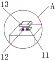
Fig. 1 is a schematic diagram of an overall structure of a storage device for software engineering according to the present invention;
fig. 2 is a schematic view of the structure of the part a in fig. 1 of the present invention;
FIG. 3 is a schematic structural view of a positioning plate of the present invention;
fig. 4 is a schematic structural view of the strip rack of the present invention.
Illustration of the drawings:
1. a storage device body; 2. a memory; 3. circular holes are formed; 4. fixing the connecting shaft; 5. a bobbin; 6. a data line; 7. a rectangular interface; 8. a clamping hole; 9. a data transmission joint; 10. a USB connector; 11. a rectangular groove; 12. a return spring; 13. a connection bump; 14. positioning a plate; 141. connecting a stud; 142. a pin hole; 15. a strip-shaped frame; 151. adjusting the sliding chute; 152. and (4) clamping a pin.
Detailed Description
The technical solutions in the embodiments of the present invention will be described clearly and completely with reference to the accompanying drawings in the embodiments of the present invention, and it is obvious that the described embodiments are only some embodiments of the present invention, not all embodiments.
As shown in fig. 1-2, a storage device for software engineering, comprising: the storage device comprises a storage device body 1, a winding frame 5 and a data transmission joint 9;
a memory 2 is arranged in the rear end of the storage device body 1, a circular opening 3 is formed in the storage device body 1, a fixed connecting shaft 4 is rotatably connected to the center of the circular opening 3, and a rectangular interface 7 is further arranged at the front end of the storage device body 1;
the bobbin 5 is embedded in the inner side of the circular opening 3, the bobbin 5 is rotatably sleeved on the fixed connecting shaft 4, the data wire 6 is wound on the bobbin 5, and one end of the data wire 6 is connected with the memory 2;
the data transmission joint 9 is detachably embedded and connected on the rectangular interface 7, the outer side of the data transmission joint 9 is connected with a USB joint 10, and the data transmission joint 9 is connected with the other end of the data line 6.
The data transmission joint 9 is electrically connected with the memory 2 through the data line 6, and the memory 2 is matched with the data transmission joint 9 through the data line 6 to realize data storage and transmission.
The bilateral symmetry of rectangle interface 7 has seted up joint hole 8, and the position in joint hole 8 and the position of connecting lug 13 correspond each other, and joint hole 8 cooperation connecting lug 13 carries out the joint to fix the data transmission joint 9 of embedding connection in the rectangle interface 7.
The working principle is as follows: when the storage device for software engineering is used, the data transmission connector 9 is embedded and connected in the rectangular interface 7 through the connecting convex blocks 13 at the two sides of the data transmission connector, when data storage is carried out, the USB connector 10 on the data transmission connector 9 can be connected with a USB interface on the equipment, and then the data is stored in the memory 2 through the data line 6, in special occasions, the connecting lug 13 can be used, so that the connecting lug 13 is embedded into the inner side of the rectangular groove 11, then the data transmission connector 9 is taken out from the rectangular interface 7 on the storage device body 1, and then the storage device is transferred to the winding frame 5 to loosen the data wire 6 wound and coiled on the winding frame, then, the USB connector 10 on the data transmission connector 9 can be directly connected with an interface on the equipment without being connected with the storage device body 1, so that the connection and the storage of data are more convenient.
As shown in fig. 3 and 4, the top end of the fixed connecting shaft 4 penetrates through the bobbin 5 and is connected to the positioning plate 14 through the connecting stud 141, and pin holes 142 are symmetrically formed on the outer side of the positioning plate 14.
The bilateral symmetry that the surface of bobbin 5 is located positioning disk 14 is equipped with bar frame 15, and has seted up on bar frame 15 and has adjusted spout 151, and the slip embedding is connected with joint round pin 152 on adjusting spout 151.
When taking out data transmission joint 9 and using, after rotating the length that bobbin 5 adjusted data line 6, can rotate the position of positioning disk 14 through connecting stud 141 and adjust then fix, fixed completion back, the joint round pin 152 in the bar frame 15 in the slip regulation bobbin 5 outside for joint round pin 152 imbeds in the pinhole 142 on positioning disk 14, then fix bobbin 5 through joint round pin 152 cooperation positioning disk 14, it leads to data line 6 and the disconnection of memory 2 hookup location department to prevent unexpected tensile data line 6 during the use, thereby protect data line 6.
In the description herein, references to the description of "one embodiment," "an example," "a specific example," etc., mean that a particular feature, structure, material, or characteristic described in connection with the embodiment or example is included in at least one embodiment or example of the invention. In this specification, the schematic representations of the terms used above do not necessarily refer to the same embodiment or example. Furthermore, the particular features, structures, materials, or characteristics described may be combined in any suitable manner in any one or more embodiments or examples.
The above, only be the concrete implementation of the preferred embodiment of the present invention, but the protection scope of the present invention is not rectangular, and any person skilled in the art is in the technical scope of the present invention, according to the present invention, the technical solution and the utility model thereof should be covered within the protection scope of the present invention.
Claims (6)
1. A storage device for software engineering, comprising: the storage device comprises a storage device body (1), a winding frame (5) and a data transmission joint (9);
a memory (2) is installed inside the rear end of the storage device body (1), a circular opening (3) is formed in the storage device body (1), a fixed connecting shaft (4) is rotatably connected to the center of the circular opening (3), and a rectangular interface (7) is further arranged at the front end of the storage device body (1);
the winding frame (5) is embedded in the inner side of the circular hole (3), the winding frame (5) is rotatably sleeved on the fixed connecting shaft (4), the data wire (6) is connected to the winding frame (5) in a winding mode, and one end of the data wire (6) is connected with the memory (2);
the data transmission connector (9) is detachably embedded and connected onto the rectangular interface (7), the outer side of the data transmission connector (9) is connected with the USB connector (10), and the data transmission connector (9) is connected with the other end of the data line (6).
2. A storage device for software engineering according to claim 1, characterized in that the data transmission connector (9) is electrically connected to the memory (2) via a data line (6).
3. The storage device for software engineering according to claim 1, wherein rectangular grooves (11) are symmetrically formed in two sides of the data transmission joint (9), and the rectangular grooves (11) are connected with connecting bumps (13) through return springs (12).
4. The storage device for software engineering according to claim 1, wherein the rectangular interface (7) has two symmetrical clamping holes (8), and the positions of the clamping holes (8) correspond to the positions of the connecting bumps (13).
5. The storage device for software engineering according to claim 1, wherein the top end of the fixed connecting shaft (4) penetrates through the bobbin (5) and is connected with the positioning plate (14) through a connecting stud (141), and pin holes (142) are symmetrically formed in the outer side of the positioning plate (14).
6. The storage device for the software engineering according to claim 1, wherein the surface of the bobbin (5) is symmetrically provided with strip-shaped frames (15) at two sides of the positioning plate (14), the strip-shaped frames (15) are provided with adjusting sliding grooves (151), and the adjusting sliding grooves (151) are connected with clamping pins (152) in a sliding embedded manner.
Priority Applications (1)
| Application Number | Priority Date | Filing Date | Title |
|---|---|---|---|
| CN201921878121.0U CN210325205U (en) | 2019-11-04 | 2019-11-04 | Storage device for software engineering |
Applications Claiming Priority (1)
| Application Number | Priority Date | Filing Date | Title |
|---|---|---|---|
| CN201921878121.0U CN210325205U (en) | 2019-11-04 | 2019-11-04 | Storage device for software engineering |
Publications (1)
| Publication Number | Publication Date |
|---|---|
| CN210325205U true CN210325205U (en) | 2020-04-14 |
Family
ID=70134752
Family Applications (1)
| Application Number | Title | Priority Date | Filing Date |
|---|---|---|---|
| CN201921878121.0U Expired - Fee Related CN210325205U (en) | 2019-11-04 | 2019-11-04 | Storage device for software engineering |
Country Status (1)
| Country | Link |
|---|---|
| CN (1) | CN210325205U (en) |
Cited By (1)
| Publication number | Priority date | Publication date | Assignee | Title |
|---|---|---|---|---|
| CN113299323A (en) * | 2021-05-26 | 2021-08-24 | 深圳市索麦科技有限公司 | Independent caching device for tablet personal computer data |
-
2019
- 2019-11-04 CN CN201921878121.0U patent/CN210325205U/en not_active Expired - Fee Related
Cited By (2)
| Publication number | Priority date | Publication date | Assignee | Title |
|---|---|---|---|---|
| CN113299323A (en) * | 2021-05-26 | 2021-08-24 | 深圳市索麦科技有限公司 | Independent caching device for tablet personal computer data |
| CN113299323B (en) * | 2021-05-26 | 2022-11-01 | 深圳市索麦科技有限公司 | Independent caching device for tablet personal computer data |
Similar Documents
| Publication | Publication Date | Title |
|---|---|---|
| CN210325205U (en) | Storage device for software engineering | |
| CN201877127U (en) | USB (Universal Serial Bus) flash disk capable of preventing important data from being lost | |
| CN208904374U (en) | A kind of storage data line | |
| CN209675617U (en) | A kind of data line of the flexible storage of portable double-length | |
| CN210515348U (en) | Storage device for cloud computer | |
| CN209981604U (en) | Elbow data line | |
| CN207572671U (en) | A kind of USB plug with dust protection | |
| CN210214406U (en) | Multi-functional data line receiver that stretches out and draws back | |
| CN212323358U (en) | Power and data line storage device | |
| CN208257904U (en) | The mobile phone shell of included earphone | |
| CN215773517U (en) | Earphone with card taking needle | |
| CN209858627U (en) | Point measuring pen | |
| CN215732387U (en) | Novel shield for data interface of automobile central control system | |
| CN218547434U (en) | Computer hard disk with outer wrapping protection mechanism | |
| CN217043936U (en) | Computer dust keeper | |
| CN217934406U (en) | Memory convenient to plug | |
| CN212392459U (en) | Mobile phone data line | |
| CN213303038U (en) | Read-write machine with fast and stable interface | |
| CN211208825U (en) | Combined plugboard with stable fixing mechanism | |
| CN204732163U (en) | USB flash disk is inserted in novel two sides namely | |
| CN210243702U (en) | High-precision high-resistance direct-current grounding finder | |
| CN219289910U (en) | Portable retractable silica gel earplug | |
| CN216122415U (en) | Portable NFC wireless intelligent communication device | |
| CN210956146U (en) | Portable electronic information memory | |
| CN216625971U (en) | Portable electric energy meter data reading wireless device |
Legal Events
| Date | Code | Title | Description |
|---|---|---|---|
| GR01 | Patent grant | ||
| GR01 | Patent grant | ||
| CF01 | Termination of patent right due to non-payment of annual fee |
Granted publication date: 20200414 Termination date: 20201104 |
|
| CF01 | Termination of patent right due to non-payment of annual fee |