CN210323426U - Iron detector capable of reading depth - Google Patents
Iron detector capable of reading depth Download PDFInfo
- Publication number
- CN210323426U CN210323426U CN201921758488.9U CN201921758488U CN210323426U CN 210323426 U CN210323426 U CN 210323426U CN 201921758488 U CN201921758488 U CN 201921758488U CN 210323426 U CN210323426 U CN 210323426U
- Authority
- CN
- China
- Prior art keywords
- rod
- outer side
- side wall
- probe
- probe rod
- Prior art date
- Legal status (The legal status is an assumption and is not a legal conclusion. Google has not performed a legal analysis and makes no representation as to the accuracy of the status listed.)
- Active
Links
Images


Landscapes
- Golf Clubs (AREA)
Abstract
The utility model discloses a depth-readable iron detector, which belongs to the technical field of iron detectors and comprises a probe rod, wherein a main machine is fixedly arranged on the outer side wall of the top end of the probe rod, a display screen is arranged on the upper surface of the main machine, a handle is fixedly welded between the upper surface of the main machine and the outer side wall of the probe rod, an adjusting rod is sleeved inside the bottom end of the probe rod, and a fixing bolt is connected with the outer side wall of the bottom end of the probe rod through threads; when carrying out installation work to visiting the dish, the pulling ring makes the spring be in the shrink state, will visit the inboard of dish installation to the mounting disc lower surface again, utilize the elasticity of spring to make in the one end joint draw-in groove of slide bar behind the loosening pull ring, accomplish the fixed to visiting the dish, dismantle simultaneously also convenient and fast more, the installation effectiveness who visits the dish has greatly been improved, the holistic portability has been improved, utilize electric putter's drive simultaneously, thereby the angle of visiting the dish is changed, and then adapt to more complicated topography, excellent in use effect.
Description
Technical Field
The utility model belongs to the technical field of the iron ware of exploring, concretely relates to iron ware of exploring of readable degree of depth.
Background
The metal detector is mainly used for detecting and identifying buried underground metal objects and is widely used for safety inspection, archaeology, prospecting and finding waste metals and the like.
At present, the spy dish on the present spy ironware generally uses screw etc. to install to the probe rod on, there is inconvenience during installation and dismantlement, and the installation effectiveness is low, and the length of probe rod and the angle of spying the dish are difficult to adjust, have certain inconvenience during the use.
SUMMERY OF THE UTILITY MODEL
An object of the utility model is to provide a can read iron detector of degree of depth to solve the problem that proposes among the above-mentioned background art.
In order to achieve the above object, the utility model provides a following technical scheme: a depth-readable iron detector comprises a probe rod, a host is fixedly installed on the outer side wall of the top end of the probe rod, a display screen is arranged on the upper surface of the host, a handle is fixedly welded between the upper surface of the host and the outer side wall of the probe rod, an adjusting rod is sleeved inside the bottom end of the probe rod, a fixing bolt is connected to the outer side wall of the bottom end of the probe rod in a threaded manner, a plurality of screw holes are formed in the outer side wall of the adjusting rod and matched with the fixing bolt for use, the bottom end of the adjusting rod is hinged to the upper surface of a mounting disc, two sliding sleeves are connected to the outer side wall of the mounting disc in a clamping manner and sleeved with sliding rods, a pull ring is fixedly connected to one end of each sliding rod, the other end of each sliding rod is inserted into a clamping groove formed in the upper portion of the probe disc, a fixing block is fixedly connected, the electric push rod is electrically connected with a lithium battery arranged inside the host.
By adopting the scheme, when the detection disc is installed for work by arranging the pull ring, the slide rod, the slide sleeve, the spring and the limiting block, the pull ring is pulled to enable the spring to be in a contraction state, the detection disc is installed on the inner side of the lower surface of the installation disc, after the pull ring is loosened, one end of the sliding rod is clamped in the clamping groove by the aid of elasticity of the spring, the detection disc is fixed, meanwhile, the disassembly is more convenient and faster, the installation efficiency of the probe disc is greatly improved, the integral portability is improved, by arranging the fixing bolt, the screw hole and the electric push rod, the fixing bolt is firstly rotated to rotate out of the screw hole, the fixing of the adjusting rod is released, the extending length of the adjusting rod can be adjusted, thereby the crowd of adaptation different heights uses, utilizes electric putter's drive simultaneously to the angle of change spy dish, and then adapts to more complicated topography, excellent in use effect.
What needs to be explained in the above scheme is:
the electric push rod can be ZLD-TG-200 MM.
In a preferred embodiment, a bracket is welded and fixed to the top end of the probe rod, an elastic band is fixedly connected to one side of the bracket, and a buckle is connected to the elastic band.
By adopting the scheme, the waist of the staff is convenient to fix by utilizing the bracket and the elastic band, so that the use is more labor-saving and convenient, and the buckle is convenient to connect or remove the fixation of the elastic band.
In a preferred embodiment, a pull ring is fixedly connected to one end of the slide rod away from the mounting plate.
By adopting the scheme, the pull ring is convenient for pulling the push rod to separate from the clamping groove, so that the disassembly work is completed.
As a preferred embodiment, the lateral wall fixedly connected with stopper of slide bar, and the stopper laminates with the lateral wall of visiting the dish, the lateral wall cover of slide bar is equipped with the spring, and the both ends of spring respectively with the opposite face fixed connection of mounting disc and stopper.
By adopting the scheme, when the slide bar is pulled, the limiting block moves along with the slide bar at the moment, so that the spring is compressed, and after the pull ring is loosened, the elastic force of the spring is utilized to clamp one end of the slide bar in the clamping groove, so that the fixing of the detection disc is completed.
As a preferred embodiment, a threading ring is fixedly connected to the outer side wall of the bottom end of the probe rod.
By adopting the scheme, the arrangement of the threading rings is convenient for fixing the connecting wires, and the connecting wires are prevented from being randomly placed to influence detection work.
Compared with the prior art, the beneficial effects of the utility model are that:
according to the depth-readable iron detector, due to the arrangement of the pull ring, the slide rod, the sliding sleeve, the spring and the limiting block, when the detection disc is installed, the pull ring is pulled to enable the spring to be in a contraction state, then the detection disc is installed to the inner side of the lower surface of the installation disc, after the pull ring is loosened, one end of the slide rod is clamped in the clamping groove through the elasticity of the spring, the detection disc is fixed, meanwhile, the dismounting is more convenient and faster, the installation efficiency of the detection disc is greatly improved, and the overall portability is improved;
this iron ware is visited to readable degree of depth is through setting up fixing bolt, screw and electric putter, rotates fixing bolt earlier and makes fixing bolt rotate out from the screw, removes the fixed of adjusting the pole, can adjust the extension length of adjusting the pole this moment to the crowd that adapts to different heights uses, utilizes electric putter's drive simultaneously, thereby changes the angle of visiting the dish, and then adapts to more complicated topography, excellent in use effect.
Drawings
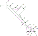
Fig. 1 is a schematic structural view of the present invention;
fig. 2 is a schematic structural view of the elastic band of the present invention viewed from above;
fig. 3 is an enlarged schematic structural diagram of the position a of the present invention.
In the figure: 1. a probe rod; 2. a host; 3. a display screen; 4. a grip; 5. a bracket; 6. elastic bands; 7. buckling; 8. adjusting a rod; 9. a screw hole; 10. fixing the bolt; 11. mounting a disc; 12. a sliding sleeve; 13. a slide bar; 14. a pull ring; 15. a limiting block; 16. a spring; 17. a card slot; 18. detecting a disc; 19. a fixed block; 20. an electric push rod; 21. a hinged block; 22. a threading ring.
Detailed Description
The present invention will be further described with reference to the following examples.
The following examples are intended to illustrate the invention, but are not intended to limit the scope of the invention. The condition in the embodiment can be further adjusted according to concrete condition the utility model discloses a it is right under the design prerequisite the utility model discloses a simple improvement of method all belongs to the utility model discloses the scope of claiming.
Referring to fig. 1-3, the present invention provides a depth-readable iron detector, which includes a detecting rod 1, a main unit 2 is fixedly installed on the outer side wall of the top end of the detecting rod 1, and a display screen 3 (see fig. 1) is arranged on the upper surface of the main unit 2; the display screen 3 is utilized to display the detection depth information, so that the workers can read the position of the object under the ground conveniently.
A handle 4 is welded and fixed between the upper surface of the main machine 2 and the outer side wall of the probe rod 1, a bracket 5 is welded and fixed at the top end of the probe rod 1, an elastic band 6 is fixedly connected to one side of the bracket 5, and a buckle 7 is connected to the elastic band 6 (see fig. 1 and 2); the waist of a worker can be conveniently fixed by utilizing the bracket 5 and the elastic band 6, so that the use is more labor-saving and convenient, and the buckle 7 is convenient for connecting or releasing the fixation of the elastic band 6.
An adjusting rod 8 is sleeved inside the bottom end of the probe rod 1, a fixing bolt 10 is connected to the outer side wall of the bottom end of the probe rod 1 in a threaded mode, a plurality of screw holes 9 are formed in the outer side wall of the adjusting rod 8, the screw holes 9 are matched with the fixing bolt 10 for use, the bottom end of the adjusting rod 8 is hinged to the upper surface of the mounting disc 11, two sliding sleeves 12 are connected to the outer side wall of the mounting disc 11 in a clamped mode, sliding rods 13 are sleeved on the two sliding sleeves 12, and a pull ring 14 (see fig. 1 and 3) is fixedly connected to; the pull ring 14 is used for conveniently pulling the push rod to separate the push rod from the clamping groove 17, and the disassembly work is completed.
One end of a sliding rod 13 is fixedly connected with a pull ring 14, the other end of the sliding rod 13 is inserted into a clamping groove 17 formed in the upper portion of a detection disc 18, the outer side wall of the sliding rod 13 is fixedly connected with a limiting block 15, the limiting block 15 is attached to the outer side wall of the detection disc 18, a spring 16 is sleeved on the outer side wall of the sliding rod 13, and two ends of the spring 16 are respectively and fixedly connected with the opposite surfaces of the mounting disc 11 and the limiting block 15 (see fig. 1 and 3); when the sliding rod 13 is pulled, the limiting block 15 moves along with the sliding rod 13 at the moment, so that the spring 16 is compressed, after the pull ring 14 is loosened, one end of the sliding rod 13 is clamped in the clamping groove 17 by using the elasticity of the spring 16, and the fixing of the detection disc 18 is completed.
Adjust the lateral wall fixedly connected with fixed block 19 of pole 8, and the lower surface of fixed block 19 and the upper surface of mounting disc 11 all through articulated piece 21 and electric putter 20's both ends fixed connection, electric putter 20 and host computer 2 internally mounted's lithium cell electric connection.
The outer side wall of the bottom end of the probe rod 1 is fixedly connected with a threading ring 22 (see figure 1); the setting of thimble 22 is convenient for fix the connecting wire, avoids the connecting wire to put the influence detection work wantonly.
When the adjustable type telescopic pull rod is used, installation and adjustment work is firstly carried out, when the detection disc 18 is installed, the pull ring 14 is pulled to move along with the slide rod 13 by utilizing the limiting block 15 so that the spring 16 is in a contraction state, then the detection disc 18 is installed to the inner side of the lower surface of the installation disc 11, after the pull ring 14 is loosened, one end of the slide rod 13 is clamped in the clamping groove 17 by utilizing the elasticity of the spring 16, the detection disc 18 is fixed, meanwhile, the disassembly is more convenient and rapid, the installation efficiency of the detection disc 18 is greatly improved, the integral portability is improved, if the extension length of the adjustment rod 8 needs to be adjusted, the fixing bolt 10 is firstly rotated to enable the fixing bolt 10 to rotate out of the screw hole 9, the fixing of the adjustment rod 8 is released, the extension length of the adjustment rod 8 can be adjusted at the moment, so that the adjustable type telescopic pull rod is suitable for people with different heights, the fixing bolt 10, thereby change the angle of exploring the dish 18, and then adapt to more complicated topography, excellent in use effect, after installation regulation work preparation finishes, tie up elastic cord 6 to the waist to hold grip 4, can begin to use.
Although embodiments of the present invention have been shown and described, it will be appreciated by those skilled in the art that changes, modifications, substitutions and alterations can be made in these embodiments without departing from the principles and spirit of the invention, the scope of which is defined in the appended claims and their equivalents.
Claims (5)
1. A depth-readable iron detector comprises a detection rod (1), and is characterized in that: the outer side wall of the top end of the probe rod (1) is fixedly provided with a host (2), the upper surface of the host (2) is provided with a display screen (3), a handle (4) is fixedly welded between the upper surface of the host (2) and the outer side wall of the probe rod (1), an adjusting rod (8) is sleeved inside the bottom end of the probe rod (1), the outer side wall of the bottom end of the probe rod (1) is in threaded connection with a fixing bolt (10), the outer side wall of the adjusting rod (8) is provided with a plurality of screw holes (9), the screw holes (9) are matched with the fixing bolt (10) for use, the bottom end of the adjusting rod (8) is hinged on the upper surface of a mounting disc (11), the outer side wall of the mounting disc (11) is connected with two sliding sleeves (12) in a clamping way, the two sliding sleeves (12) are both provided with a sliding rod (13), one end of the sliding rod (13) is fixedly connected with a pull ring (14), the, the outer side wall fixedly connected with fixed block (19) of adjusting pole (8), and the lower surface of fixed block (19) and the upper surface of mounting disc (11) all through articulated piece (21) and the both ends fixed connection of electric putter (20), electric putter (20) and host computer (2) internally mounted's lithium cell electric connection.
2. The depth-readable iron probe of claim 1, wherein: the top welded fastening of probe rod (1) has bracket (5), and one side fixedly connected with elastic cord (6) of bracket (5), be connected with buckle (7) on elastic cord (6).
3. The depth-readable iron probe of claim 1, wherein: one end of the sliding rod (13) far away from the mounting disc (11) is fixedly connected with a pull ring (14).
4. The depth-readable iron probe of claim 1, wherein: the utility model discloses a fixing device for the mounting plate of the automobile seat, including slide bar (13), lateral wall fixedly connected with stopper (15) of slide bar (13), and stopper (15) and the laminating of the lateral wall of visiting dish (18), the lateral wall cover of slide bar (13) is equipped with spring (16), and the both ends of spring (16) respectively with the opposite face fixed connection of mounting disc (11) and stopper (15).
5. The depth-readable iron probe of claim 1, wherein: the outer side wall of the bottom end of the probe rod (1) is fixedly connected with a threading ring (22).
Priority Applications (1)
| Application Number | Priority Date | Filing Date | Title |
|---|---|---|---|
| CN201921758488.9U CN210323426U (en) | 2019-10-21 | 2019-10-21 | Iron detector capable of reading depth |
Applications Claiming Priority (1)
| Application Number | Priority Date | Filing Date | Title |
|---|---|---|---|
| CN201921758488.9U CN210323426U (en) | 2019-10-21 | 2019-10-21 | Iron detector capable of reading depth |
Publications (1)
| Publication Number | Publication Date |
|---|---|
| CN210323426U true CN210323426U (en) | 2020-04-14 |
Family
ID=70134091
Family Applications (1)
| Application Number | Title | Priority Date | Filing Date |
|---|---|---|---|
| CN201921758488.9U Active CN210323426U (en) | 2019-10-21 | 2019-10-21 | Iron detector capable of reading depth |
Country Status (1)
| Country | Link |
|---|---|
| CN (1) | CN210323426U (en) |
-
2019
- 2019-10-21 CN CN201921758488.9U patent/CN210323426U/en active Active
Similar Documents
| Publication | Publication Date | Title |
|---|---|---|
| CN210323426U (en) | Iron detector capable of reading depth | |
| CN107367517B (en) | Digital ray detection support system taking GIS cylinder as support | |
| CN109541270B (en) | Electrical fault diagnosis instrument for mechanical equipment | |
| CN209979626U (en) | Soil and water conservation water erosion monitoring device convenient to fix and monitoring angle is adjustable | |
| CN108254314A (en) | A kind of portable pipeline detector | |
| CN104003074A (en) | Micro resistivity scanning imaging logger electrode protection sleeve | |
| CN206638227U (en) | A kind of new RTK measuring instruments for power circuit exploration | |
| CN216900420U (en) | Bridge crack detection device | |
| CN213714285U (en) | Wall surface flatness detection tool | |
| CN207830930U (en) | A kind of Acquisition Instrument assembly equipment | |
| CN210142082U (en) | Appearance is patrolled and examined to sport equipment and sports facility | |
| CN209102919U (en) | A kind of underground metalliferous survey meter | |
| CN207114120U (en) | A kind of hinged gap of plate-girder-hinged bridge detecting system | |
| CN112315442A (en) | High accuracy rhythm of heart detector for sports training | |
| CN213517603U (en) | Object approach detection sensing device based on Internet of things | |
| CN217762889U (en) | Three-dimensional detector | |
| CN211855703U (en) | Subway tunnel leakage monitoring and early warning device | |
| CN211086648U (en) | Iron detector with adjusting function | |
| CN218601488U (en) | Cavity detection instrument | |
| CN219434095U (en) | Follow-on crack surveys equipment | |
| CN213544435U (en) | Convenient type video search appearance | |
| CN210347191U (en) | Sampling device for geological survey | |
| CN212154394U (en) | Double-wire-clamping protective guard | |
| CN218580425U (en) | Road surface flatness detection device | |
| CN214845011U (en) | Hollowing detection hammer for construction site |
Legal Events
| Date | Code | Title | Description |
|---|---|---|---|
| GR01 | Patent grant | ||
| GR01 | Patent grant |